

 How to Professionally Rebuild and
Modify Kohler Engines to Produce More Power
How to Professionally Rebuild and
Modify Kohler Engines to Produce More Power
How to Professionally Rebuild and
Modify Kohler Engines to Produce More Power
How to Professionally Rebuild and
Modify Kohler Engines to Produce More Power
Educating and Inspiring Small Engine, Lawn & Garden, and Garden
Pulling Tractor Enthusiasts Since 1996. Where Science and Common Sense Come
Together for Safety and Improved Engine/Tractor Performance |
A-1
Miller's Performance Enterprises - Parts & Services
Webstore |  Available Soon - Detailed Illustrated Plans
on How to Construct a Professional Pull-Back and Self-Propelled Garden
Tractor/Small Wheel Mini Rod Pulling Sleds
Available Soon - Detailed Illustrated Plans
on How to Construct a Professional Pull-Back and Self-Propelled Garden
Tractor/Small Wheel Mini Rod Pulling Sleds
Updated 9/9/25. Click
Refresh to see any
changes or updates. Optimized for 1152 x 864 computer screen resolution.
To search for a word or phrase in any of my websites, press the CTRL
 and F
and F  keys on
your keyboard simultaneously to open the Find or Search dialog box in your
web browser. And being I have no
apprentice to update and pay for my websites so they'll
continue to be on the Internet, they will be removed forever when I'm no
longer around. Scroll down this website or click/tap the links below to
jump down to...
keys on
your keyboard simultaneously to open the Find or Search dialog box in your
web browser. And being I have no
apprentice to update and pay for my websites so they'll
continue to be on the Internet, they will be removed forever when I'm no
longer around. Scroll down this website or click/tap the links below to
jump down to...
Decoding Kohler K-series and Magnum Engine Model, Specification and Serial Identification Numbers -

 The Kohler K-series and Magnum engine
model and serial numbers appear on an adhered metallic vinyl label or a riveted
aluminum plate that's affixed to the flywheel shroud. If there's no plate
or label on the shroud, if the printed ink lettering and numbers on the plate
or label is faded away, or if the shroud was replaced with one from another
engine, then there's no way of knowing exactly which specific parts the engine
requires or the year the engine was manufactured. If the plate or label have
legible wording and numbers, all you'll know is the model, specification
and year of the flywheel shroud itself. Because flywheel shrouds can
be swapped from one engine to another and unlike most automotive engines
with identification numbers stamped directly on the block, there are no
identification numbers on Kohler engine blocks themselves. Only an experienced
and knowledgeable Kohler K-series or Magnum engine mechanic will know exactly
which specific parts the engine requires. Certain Kohler K-series engines
have the model number embossed on the Power Take Off (PTO) end of the block,
but this is rare. Therefore, if the flywheel shroud is missing or if it's
mismatched with the correct engine, the only true way finding for sure the
size and model is to remove the cylinder head and measure the bore and stroke.
Otherwise, they're like the early small and big block Chevy V8's, and the
Chevy 348 and 409 "W" engines
The Kohler K-series and Magnum engine
model and serial numbers appear on an adhered metallic vinyl label or a riveted
aluminum plate that's affixed to the flywheel shroud. If there's no plate
or label on the shroud, if the printed ink lettering and numbers on the plate
or label is faded away, or if the shroud was replaced with one from another
engine, then there's no way of knowing exactly which specific parts the engine
requires or the year the engine was manufactured. If the plate or label have
legible wording and numbers, all you'll know is the model, specification
and year of the flywheel shroud itself. Because flywheel shrouds can
be swapped from one engine to another and unlike most automotive engines
with identification numbers stamped directly on the block, there are no
identification numbers on Kohler engine blocks themselves. Only an experienced
and knowledgeable Kohler K-series or Magnum engine mechanic will know exactly
which specific parts the engine requires. Certain Kohler K-series engines
have the model number embossed on the Power Take Off (PTO) end of the block,
but this is rare. Therefore, if the flywheel shroud is missing or if it's
mismatched with the correct engine, the only true way finding for sure the
size and model is to remove the cylinder head and measure the bore and stroke.
Otherwise, they're like the early small and big block Chevy V8's, and the
Chevy 348 and 409 "W" engines  ,
there's no way of knowing for sure simply by looking at it from the outside.
Because a Kohler K241 or M10 engine block can be bored and stroked to a model
K301, M12, using the K301 or M12 piston, rod and crankshaft, and a K301 or
M12 block can be bored to a model K321 or M14 using the K321 or M14 piston,
rod and crankshaft. But the models K341 or M16 blocks are in a class by
themselves. A K321 or M14 block could be bored for the K341 or M16 piston,
but doing this would make the cylinder wall about 1/8" thick, or the boring
process could break through the cylinder wall without centering the boring
bar according to the outside of the cylinder beforehand. Therefore, this
is NOT recommended.
,
there's no way of knowing for sure simply by looking at it from the outside.
Because a Kohler K241 or M10 engine block can be bored and stroked to a model
K301, M12, using the K301 or M12 piston, rod and crankshaft, and a K301 or
M12 block can be bored to a model K321 or M14 using the K321 or M14 piston,
rod and crankshaft. But the models K341 or M16 blocks are in a class by
themselves. A K321 or M14 block could be bored for the K341 or M16 piston,
but doing this would make the cylinder wall about 1/8" thick, or the boring
process could break through the cylinder wall without centering the boring
bar according to the outside of the cylinder beforehand. Therefore, this
is NOT recommended.
Bore, Stroke and Valve Sizes of Kohler K-series and Magnum engines:
| Engine Model | K90/K91 | K141 (early) | K141 (later) | K160/K161, KV161, L160/L161 (early models) | K160/K161, KV161, L160/L161 (later models) | L181, K181 and M8 | K241 and M10 | K301 and M12 | K330/K331 | K321 and M14 | K341 and M16 | K361 (OHV) | |
| Bore (STD) | 2.375" | 2.875" | 2.938" | 2.875" | 2.938" | 2.938" | 3.250" | 3.375" | 3.625" | 3.500" | 3.750" | 3.750" | |
| Stroke | 2.000" | 2.500" | 2.500" | 2.500" | 2.500" | 2.750" | 2.875" | 3.250" | 3.250" | 3.250" | 3.250" | 3.250" | |
| Cubic Inch Displacement | 8.86 | 16.23 | 16.94 | 16.23 | 16.94 | 18.64 | 23.85 | 29.08 | 33.54 | 31.27 | 35.895 | 35.895 | |
| Minimum Safe Idle Speed | <-1,200 RPM (±75 RPM)-> | ||||||||||||
| Factory-Rated Horsepower at Maximum Safe Operating Speed |
4hp at 4,000 RPM | 6¼hp at 3,200 RPM | 7hp at 3,600 RPM | 6¼hp at 3,200 RPM | 6.6hp at 3,600 RPM | 7hp at 3,600 RPM | 8hp at 3,600 RPM | 10hp at 3,600 RPM | 12hp at 3,600 RPM | 12½hp at 3,200 RPM | 14hp at 3,600 RPM | 16hp at 3,600 RPM | 18hp at 3,600 RPM | |
| Valve Size (Head diameter) | Intake | 1.262" | 1-3/8" | 1-3/8" | 1-3/8" | 1-3/8" | 1-3/8" | 1-3/8" | 1-3/8" | ? | 1-3/8" | 1-3/8" | 1-7/16" |
| Exhaust | 1.262" | 1-1/8" | 1-1/8" | 1-1/8" | 1-1/8" | 1-1/8" | 1-1/8" | 1-1/8" | ? | 1-1/8" (Early K321's) 1-3/8" (Later K321's with specification suffix "D" and later, and all M14's) |
1-3/8" | 1-13/32" | |
How to Decode the Model Numbers of Kohler K-series and Magnum Engines - These determine the size and basic description of the engine.
| Example of Model K161 -> K = K-series engine | 16 = Cubic inch
displacement (approximate) | 1 = One/single cylinder engine
Example of Model KV161 -> K = K-series engine | V = Vertical crankshaft | 16 = Cubic inch displacement (approximate) | 1 = One/single cylinder engine Example of Model L161 -> L = Liquid-cooled engine | 16 = Cubic inch displacement (approximate) | 1 = One/single cylinder engine Example of Model K301AQS -> K = K-series engine | 30 = Cubic inch displacement (approximate) | 1 = One/single cylinder engine | A = Narrow Base Block and/or Special Oil Pan | Q = Quiet Model "Quiet Line" | S = Electric (Gear) Start Example of Model M14PT -> M = Magnum series engine | 14 = Horsepower rating | PT = Pump model/Retractable start Example of Model KT17 -> K = K-series engine | T = Twin cylinder | 17 = Horsepower rating Example of Model M18 -> M = Magnum engine | 18 = Horsepower rating Example of Model K482 -> K = K-series engine | 48 = Cubic inch displacement (approximate) | 2 = Two (twin) cylinder engine By the way - The model numbers corresponding to Kohler engine models K90/K91, K160/K161, K330/K331, and K660/K662 are basically the same engines, respectively. Beginning in 1965, Kohler changed the "0" to "1" or "2" at the end of the model number to indicate that it's a one (1) or two (2) cylinder engine. The History of Kohler Engines | eHow. |
How to Decode the Version Codes for Kohler K-series and Magnum Single- and Opposed Twin-Cylinder Engines - These are the letter(s) immediately following the engine model number, indicating the type of engine.
| A = Narrow
Base Block w/Narrow Oil Pan and/or Special Oil Pan B = Basic Engine C = Clutch (OEM Kohler Mechanical Clutch Unit) |
G = Generator
(Electric Power Plant) P = (Water) Pump Q = Quiet Line Model |
R = Reduction
Gear S = Electric (Gear) Start T = Recoil Start |
ST = Electric (Gear) Start and Recoil
Start EP = Electric Power Plant (Portable or Stationary Stand-By Generator) |
How to Decode the Specification Numbers for Kohler K-series and Magnum Single- and Opposed Twin-Cylinder Engines - The first two numbers of the specification number indicate the engine model. The following three numbers and letter (not shown below) are the specific variation of the engine to meet the original equipment manufacturer's (OEM) specifications. No information is available from Kohler to what these numbers represent. Engine model codes with a 4th digit of 5 or greater denote Magnum engines.
| Specification Number = Model(s) of Engine | Specification Number = Model(s) of Engine | Specification Number = Model(s) of Engine | Specification Number = Model(s) of Engine | Specification Number = Model(s) of Engine |
| 26, 27, 31 = K90 and K91 | 29 = K141 | 28 = K160, K161 and
L160/L161 41, 42 = K160 and K161 (Generator Specs) |
30 = K181, L181 and M8 | 46 = K241 and M10 |
| 47 = K301 and M12 | 60 = K321 and M14 | 71 = K341 and M16 | 23 = K361 | 24 = KT17 (first design), KT17 Series II and M18 |
| 49 = KT19 (first design), KT19 Series II and M20 | 32 = KT21 | 56 = MV16 | 58 = MV18 | 57 = MV20 |
| 35 = K482 | 53 = K532 | 36 = K582 | 37, 38, 43, 44 = K330 and 331 | 29, 30, 33, 39, 45 = K660 and K662 |
How to Decode the Serial Numbers for Kohler K-series and Magnum Single- and Opposed Twin-Cylinder Engines - The letter or the first two or three numbers of the serial number indicates the year the engine was manufactured. The remaining digits of the serial number are factory code (line/shift at the factory when the engine was assembled on that day; these numbers are for warranty purposes only.) FYI - In 1951, Kohler released the model K90 engine (which is actually the K91). The model K160 (which is actually the K161) followed in 1952. No serial numbers are available these early model engines. In 1968, Kohler expanded into the small all terrain vehicle market by beginning to produce 2-cylinder snowmobile engines. In 1984, Kohler revealed new style and improvements through the Magnum series, complete with electronic ignition and "superior" air filtration system.
| Letter code. E 1 7 2 4 5 2 (example) |
If seven numbers, use the first two digits. 9 0 7 6 4 3 0 (example) |
If eight numbers, use the first three digits. 1 0 0 2 6 6 9 2 (example) |
If ten numbers, use the first two digits. 1 5 0 1 8 9 7 5 9 1 (example) |
|
| (See below for models made before 1965) A............1965 B............1966 C............1967 D............1968 E...(early)1969 |
10-19...(late)1969 20-29...........1970 30-39...........1971 40-49...........1972 50-59...........1973 60-69...........1974 70-72...........1975 73-79...........1976 80-89...........1977 90-94...........1978 95-99...........1979 |
100-109.............1980 110-119.............1981 120-129.............1982 130-139.............1983 140-149.............1984 150-159...(early)1985 |
15...(late)1985 16...........1986 17...........1987 18...........1988 19...........1989 20...........1990 21...........1991 22...........1992 23...........1993 24...........1994 25...........1995 26...........1996 27...........1997 28...........1998 |
29...........1999 30...........2000 31...........2001 32...........2002 33...........2003 34...........2004 35...........2005 36...........2006 37...........2007 38...........2008 39...........2009 40...........2010 41...........2011 |
| Before 1965, Kohler did not give any of their engines a serial
number manufacturing date. No information is available from Kohler regarding
the year of manufacture for these early engines, with the exception of the
engine model and specification numbers listed below.
K90P-2667 Carver Pump Co. 1955 | K90T-27191 Canadian Tap & Die 1957 | K91S-31544 Cart Craft Co. 1961 | K91P-3106, 3167 Carver Pump Co. 1958 | K141P-29111 Carver Pump Co. 1962 | K141-29140 Canasco Products 1963 | K160P-2881 Carver Pump Co. 1955 | K161S-28636 Canadian Golf Cars 1961 | K161S-28854 Canadian Golf Cars 1962 | K161CS-28374 Carson Machine 1959 | K161P-28643 Carver Military Pump Co. 1961 | K161T-28711 Carson Machine 1962 | K181S-30204 Canadian Golf Cars 1964 | K181S-30207 Canadian Golf Cars 1964 | K181S-30179 Capri Manufacturing/Golf Car 1963 | K301-4721 Case 1964 | K662P-3333 Carver Pump Co. 1956 | K660P-33177 Carver Pump Co. 1958 | K662P -33278 Carver Pump Co. 1960 | K662CS-33275 Cardox Corporation 1960. |
||||
Kohler Engine Models K330/K331 12-1/2 Horsepower - Sizes and Running Clearances
| PARTS FITTED | SIZE OR CLEARANCE | PARTS FITTED | SIZE OR CLEARANCE | |
| Minimum safe idle speed (RPM) Maximum safe operating speed (RPM) |
1,200 3,200 |
Breaker cam to camshaft pin | .001" - .0025" | |
| Cylinder Bore - STD size | 3.625" | Camshaft end play | .005" - .010" | |
| Closure plate to block | .001" - .005" | Tappet in block | .0008" - .0023" | |
| Crankshaft end play - Models with Oil Pump Crankshaft end play - Models with Splash Lubrication |
.003" - .008" .005" - .010" |
Valve stem in guide - Intake Valve stem in guide - Exhaust |
.002" - .005" .002" - .0035" |
|
| Connecting rod to crankpin running clearance | .0003" - .0023" | Guide in block | .0005" - .002" | |
| Connecting rod side play on crankpin | .007" - .011" | Exhaust valve seat in block | .0025" - .0045" | |
| Crankshaft connecting rod journal size | 1.873" | Transfer bearing to crankshaft, oil clearance | .001" - .0035" | |
| Connecting rod to wrist pin | .0003" - .0008" | Crankshaft gear to crankshaft | .001" - .0015" | |
| Wrist pin to piston boss | .0001" - .0003" | Output shaft seal to closure plate | .001" - .007" | |
| Ring side clearance - top ring | .0025" - .0045" | Governor gear to governor shaft | .0005" - .0015" | |
| Ring side clearance - middle ring | .0025" - .0045" | Piston to cylinder bore clearance (top thrust face) | .0005" - .0015" | |
| Ring side clearance - bottom ring | .002" - .0035" | Valve clearances (cold) - Intake | Exhaust | .008" | .020" | |
| Ring end gap | .007" - .017" | Spark plug gap - Magneto ignition Spark plug gap - Battery ignition |
.025" .035" |
|
| Camshaft pin to camshaft running clearance | .001" - .0025" | Breaker points gap | .020" | |
| Camshaft pin to block | .0015" - .003" | Spark retard (engine start) Spark advance (engine running) |
2º ATDC 15º BTDC |
Kohler K-series Single Cylinder Engine Specifications and Tolerances (All dimensions in inches.)
| Engine Model | K90/K91 | K141, KV161, K160/K161, L160/L161 | L181 and K181 | K241 | K301 | K321 | K341 | K361 (Over Head Valve) |
||||
| General Information | Minimum Safe Idle Speed (See note 11 below) | <-1,200 RPM (±75 RPM)-> | ||||||||||
| Factory-Rated Horsepower at Maximum Safe Operating Speed | 4hp at 4,000 RPM | 6¼hp at 3,200 RPM | 6.6hp at 3,600 RPM | 7hp at 3.600 RPM | 8hp at 3,600 RPM | 10hp at 3,600 RPM | 12hp at 3,600 RPM | 14hp at 3,600 RPM | 16hp at 3,600 RPM | 18hp at 3,600 RPM | ||||
| Bore x Stroke | STD. 2.375" .010" 2.385" .020" 2.395" .030" 2.405" x 2.000" |
6¼ and 6.6hp - STD. 2.875" | 7hp - STD. 2.938" .010" 2.948" .020" 2.958" .030" 2.968" x 2.500" |
STD. 2.938" .010" 2.948" .020" 2.958" .030" 2.968" x 2.750" |
STD. 3.251" .010" 3.261" .020" 3.271" .030" 3.281" x 2.875" |
STD. 3.375" .010" 3.385" .020" 3.395" .030" 3.405" x 3.250" |
STD. 3.500" .010" 3.510" .020" 3.520" .030" 3.530" x 3.250" |
STD. 3.750" .010" 3.760" .020" 3.770" .030" 3.780" x 3.250" |
STD. 3.750" .010" 3.760" .020" 3.770" .030" 3.780" x 3.250" |
||||
| Cubic Inch Displacement (STD Bore) | 8.86 | 16.23 (K141) 16.95 (K161) |
18.64 | 23.85 | 29.07 | 31.27 | 35.90 | 35.90 | ||||
| Compression Ratio | 6.6:1 | 5.93:1 (K141) 6.2:1 (K161) |
6.8:1 | 5:1, 5.4:1 or 7.1:1 (See note 8 below) | 6.2:1, 6.6:1 or 8.6:1 (See note 8 below) | 6.6:1, 7:1 or 9:1 (See note 8 below) | 7.3:1 | 9.2:1 | ||||
| Balance Gears (Not necessarily required for K-series engines, or have rotating assembly precision balanced.) | Shaft O.D. | New | - | - | - | <-.4998"-.5001"-> | ||||||
| Maximum Wear Limit | - | - | - | <-.4996"-> | ||||||||
| Clearance/End-Play | - | - | - | <-.002"-.010"-> | ||||||||
| Camshaft | Clearance/End-Play (See note 10 below) | <-.005"-.010"-> | ||||||||||
| Connecting Rod | Running Clearance (See note 10 below) |
Maximum Big End Diameter | STD. size: .938" / .010" undersize: .928" | <-STD. size: 1.1875" / .010" undersize: 1.1775"-> | <-STD. size: 1.5015" / .010" undersize: 1.4915" / .020" undersize: 1.4815" / .030" undersize: 1.4715"-> | |||||||
| Rod to Crankpin | .001" (min.) .0025" |
<-.001"-.002"-> | ||||||||||
| Maximum Rod to Crankpin Wear Limit | .003" | <-.0025"-> | ||||||||||
| Rod to Piston Pin | .0007" (min.) .0008" |
<-.0006"-.0011"-> | <-.0003"-.0008"-> | |||||||||
| Wrist Pin Hole I.D. | .5630" (min.) .5633" |
<-.6255"-.6258"-> | .8596" (min.) .8599" |
<-.8757"-.8760"-> | ||||||||
| Crankshaft | Main PTO end and Flywheel End O.D. |
New | .9844" | <-1.1814"-> | <-1.5749"-> | |||||||
| Maximum Wear Limit | .9841" | <-1.1811"-> | <-1.5745"-> | |||||||||
| Crankpin | New (max./min.) (See note 10 below) | STD. size: .9360"-.9355" .010" undersize: .9260"-.9255" |
<-STD size: 1.1860"-1.1855", .010" undersize: 1.1760"-1.1755"-> |
STD size: 1.4995"-1.5000", .010" undersize:
1.4895"-1.4900", .020" undersize: 1.4795"-1.4800", .030" undersize: 1.4695"-1.4700" |
||||||||
| Maximum Wear Limit | STD. .9350" .010" .9340" |
<-STD. size: 1.1850" / .010" undersize: 1.1840"-> | <-STD. size: 1.4990" / .010" undersize: 1.4890" / .020" undersize: 1.4790" / .030" undersize: 1.4690"-> | |||||||||
| Maximum Out of Round | <-.0005"-> | |||||||||||
| Maximum Taper | <-.001"-> | |||||||||||
| clearance/end-play (See note 10 below) | .004" (min.) .023" |
<-.002"-.023"-> | <-.003"-.020"-> | |||||||||
| Cylinder Bore | Standard Size Cylinder Bore Diameter | New (See note 10 below) | 2.3745"-2.3755" | <-2.9370"-2.9380"-> | 3.2505"-3.2515" | 3.3745"- 3.3755" |
3.4995"- 3.5005" |
3.7495"-3.7505" | 3.7495"-3.7505" | |||
| Maximum Wear Limit | 2.378" | 2.941" | 2.941" | 3.254" | 3.378" | 3.503" | 3.753" | 3.753" | ||||
| Cylinder Bore Diameter for Oversize Piston/Rings | .010" = 2.385" .020" = 2.285" .030" = 2.405" |
.010" = 2.9475" .020" = 2.9575" .030" = 2.9675" |
.010" = 2.9475" .020" = 2.9575" .030" = 2.9675" |
.010" = 3.260" .020" = 3.270" .030" = 3.280" |
.010" = 3.385" .020" = 3.395" .030" = 3.405" |
.010" = 3.510" .020" = 3.520" .030" = 3.530" |
.010" = 3.760" .020" = 3.770" .030" = 3.780" |
.010" = 3.760" .020" = 3.770" .030" = 3.780" |
||||
| Maximum Out of Round | <-.003"-> | |||||||||||
| Maximum Taper | <-.003"-> | <-.002"-> | ||||||||||
| Cylinder Head | Maximum Out of Flatness | <-.003"-> | ||||||||||
| Ignition | Correct Spark Plug Type and Gap | Type (See note 2 below) | Autolite 255 or Champion 861 (J19LM) | <-Autolite 295 or Champion 841 (J8C)-> | <-Autolite 216 or Champion 884 (H10C)-> | |||||||
| Magneto | <-.025"-> | |||||||||||
| Battery | <-.035"-> | |||||||||||
| LP/Propane | <-.018"-> | |||||||||||
| Point Gap | Magneto | <-If no spark at .020" point gap, set gap between .015"-.018" for a stable spark and so the engine will run-> | ||||||||||
| Battery (See note 12 below) | <-Set point gap at .020" or set timing at 20º BTDC-> | |||||||||||
| All Pistons | Service Replacement Sizes | <-.010", .020", .030"-> | .010", .020", .030" | <-.010", .020", .030", .040" (aftermarket)-> | ||||||||
 (K-series Cast Piston) |
Thrust Face O.D. (See note 3 below) | New | 2.371"-2.369" | <-2.866" (K141) 2.9297"-2.9281" (K161, K181, L181)-> |
3.2432"-3.2413" | 3.368"-3.365" | 3.4941"-3.4925" | <-3.7425"-3.7410"-> | ||||
| Maximum Wear Limits | 2.366" | 2.925" | 2.925" | 3.238" | 3.363" | 3.491" | <-3.738"-> | |||||
| Thrust Face to Bore Clearance (max.) (See note 1 below) | .0035"-.006" | <-.007"-.010"-> | ||||||||||
| Ring End Gap (All 3 rings; see note 1 below) | New Bore (See note 10 below) | <-.007"-.017"-> | <-.010"-.020"-> | |||||||||
| Used Bore (Maximum) (See note 6 below) | <-.027"-> | <-.030"-> | ||||||||||
| Maximum Ring Side Clearance | <-.006"-> | |||||||||||
 (K-series Cast Piston) |
Thrust Face O.D. (See note 5 below) | New | 3.371"-2.369" | 2.9279"-2.9281" | 2.9279"-2.9281" | 3.2432"-3.2413" | 3.368"-3.365" | 3.4941"-3.4925" | <-3.7425"-3.7410"-> | |||
| Maximum Wear Limits | 2.366" | 2.925" | 2.925" | 3.238" | 3.363" | 3.491" | <-3.738"-> | |||||
| Thrust Face to Bore Clearance (max.) (See note 1 below) | .0035"-.006" | .007"-.010" | .007"-.010" | .007"-.010" | .007"-.010" | .007"-.010" | <-.007"-.010"-> | |||||
| Ring End Gap (All 3 rings.) | New Bore (See note 10 below) | .007"-.017" | .007"-.017" | .007"-.017" | .010"-.020" | .010"-.020" | .010"-.020" | <-.010"-.020"-> | ||||
| Used Bore (Maximum) (See note 6 below) | .027" | .027" | .027" | .030" | .030" | .030" | <-.030"-> | |||||
| Maximum Ring Side Clearance | .006" | .006" | .006" | .006" | .006" | .006" | <-.006"-> | |||||
 (Magnum Mahle Piston) |
Thrust Face O.D. (See notes 5, 9 below) | New / Used | - | - | 2.9329"-2.9336" | - | 3.3700"-3.3693" | 3.4945"-3.4938" | <-3.7433"-3.7426"-> | |||
| Maximum Wear Limits | - | - | 2.931" | - | 3.367" | 3.492" | <-3.7406"-> | |||||
| Thrust Face to Bore Clearance (See notes 1, 9 below) | - | - | .0034"-.0051" | - | .0045"-.0062" | .0050"-.0067" | <-.0062"-.0079"-> | |||||
| Ring End Gap (All 3 rings.) | New Bore (See note 10 below) | - | - | .010"-.023" | - | <-.010"-.020"-> | <-.013"-.025"-> | |||||
| Used Bore (Maximum) (See note 6 below) | - | - | .032" | - | <-.030"-> | <-.033"-> | ||||||
| Maximum Ring Side Clearance | - | - | .006" | - | <-.006"-> | <-.004"-> | ||||||
| Wrist Pin Outside Diameter (min.-max.) | .5623"-.5625" | <-.6247"-.6249"-> | .8591"-.8593" | <-.8752"-.8754"-> | ||||||||
| Valves | Valve Head Diameter | Intake: 63/64" Exhaust: 51/64" |
<-Intake: 1-3/8" Exhaust: 1-1/8"-> |
<-Intake: 1-3/8" Exhaust: 1-1/8"-> |
Intake: 1-3/8" Exhaust: 1-1/8" (early) / 1-3/8" (late) |
Intake: 1-3/8" Exhaust: 1-3/8" |
Intake: 1-7/16" Exhaust: 1-13/32" |
|||||
| Guide Reamer Size | .250" | <-.3125"-> | <-.3125"-> | |||||||||
| Tappet Clearance (Cold) (See notes 4, 9 below) | Intake (min.-max.) | .005"-.009" | <-.006"-.008"-> | <-.008"-.010"-> | .005"-.008" | |||||||
| Exhaust (min.-max.) | .011"-.015" | <-.017"-.019"-> | <-.017"-.019"-> | .010"-.012" | ||||||||
| Minimum Lift (Zero Lash) | Intake | .2035" | <-.2718"-> | <-.318"-> | ||||||||
| Exhaust | .1768" | <-.2482"-> | <-.318"-> | |||||||||
| Minimum Stem O.D. | Intake | .2478" | <-.3103"-> | |||||||||
| Exhaust | .2458" | <-.3088"-> | <-.3074"-> | |||||||||
| Minimum Valve Head Margin (Width) | <-.030"-> | |||||||||||
| Face / Seat Angle | <-45º / 46º-> | |||||||||||
| Guide I.D. Maximum Wear Limit (See note 1 below) | Intake | <-.005"-> | <-.006"-> | |||||||||
| Exhaust | <-.007"-> | <-.008"-> | ||||||||||
| Lifter to Bore Clearance | <-.001"-.0015"-> | |||||||||||
NOTES -
| NOTE 1 - Subtract O.D. of inner part from I.D. of outer part.
Use the lesser clearance for a stock engine (up to 4,000± RPM), and
the greater number for a higher RPM engine. Higher RPM creates more heat
due to friction, which cause greater expansion of parts. Also, when boring
or honing for piston clearance, it's important to check the ring end gaps
and gap them according to Kohler's specs. NOTE 2 - For longevity of the coil and to prevent overheating of the coil, use only metal core spark plug wire and copper core/non-resistor spark plugs. NOTE 3 - Measure just below oil ring groove and at right angles to wrist pin. NOTE 4 - 1,800 RPM generator sets at .005"- 007". NOTE 5 - Measure 1/2" above the bottom of the piston skirt. NOTE 6 - Top and center compression rings. NOTE 7 - Measure just below oil ring groove and at right angles to wrist pin. NOTE 8 - Compression ratio depends on which cylinder head is used. |
NOTE 9 - Use the lesser clearance is for a valve that have been
ran for a while, and use the greater clearance for a fresh reground valve
face and seat (As the valve and seat wear into each other, the clearance
will be lessened over time.) NOTE 10 - Use the lesser clearance for up to 3,600 RPM operation, and use the greater clearance for open RPM. NOTE 11 - Idle speed should be set at 1,200 RPM (±75 RPM) so the oil dipper can lubricate the internal moving parts more thoroughly. This speed also allows the flywheel fins to blow adequate amount of air across the cylinder head and around the cylinder fins to cool the engine better. NOTE 12 - For early model engines with the 2-piece camshaft and automatic timing advance, set points so they just begin to open when piston is positioned at top dead center (TDC) on the compression stroke. And for later model engines with the 1-piece camshaft and automatic compression release (ACR), set point gap at .020" with piston positioned at top dead center (TDC) on the compression stroke, or set static ignition timing when points begin to open exactly when S mark on flywheel passes raised line on bearing plate or hole in bearing plate. |
Kohler Magnum Single Cylinder Engine Specifications and Tolerances (All dimensions in inches)
| Engine Model | M8 | M10 | M12 | M14 | M16 | ||
| General Information | Minimum Safe Idle Speed (See note 9 below) | <-1,200 RPM (±75 RPM)-> | |||||
| Factory-Rated Horsepower at Maximum Safe Operating Speed (See note 8 below) | 7hp at 3,200 RPM 8hp at 3,600 RPM |
9hp at 3,200 RPM | 10hp at 3,600 RPM |
10.6hp at 3,200 RPM | 12hp at 3,600 RPM |
12.4hp at 3,200 RPM 14hp at 3,600 RPM |
14.2hp at 3,200 RPM 16hp at 3,600 RPM |
||
| Bore x Stroke | STD. 2.938" .010" 2.948" .020" 2.958" .030" 2.968" x 2.750" |
STD. 3.251" .010" 3.261" .020" 3.271" .030" 3.281" x 2.875" |
STD. 3.375" .010" 3.385" .020" 3.395" .030" 3.405" x 3.250" |
STD. 3.500" .010" 3.510" .020" 3.520" .030" 3.530" x 3.250" |
STD. 3.750" .010" 3.760" .020" 3.770" .030" 3.780" x 3.250" |
||
| Cubic Inch Displacement (STD Bore) | 18.64 | 23.85 | 29.07 | 31.27 | 35.90 | ||
| Balance Gears (These may be required for Magnum engines, or have rotating assembly precision balanced.) | Shaft O.D. | New | - | <-.4998"-.5001"-> | |||
| Maximum Wear Limit | - | <-.4996"-> | |||||
| Clearance/End-Play | - | <-.002"-.010"-> | |||||
| Camshaft | Clearance/End-Play (See note 6 below) | <-.005"-.010"-> | |||||
| Connecting Rod |
Running Clearance | Maximum Big End Diameter | STD. 1.1875" .010" 1.1775" |
<-STD. 1.5015" / .010" 1.4915" / .020" 1.4815" / .030" 1.4715"-> | |||
| Rod to Crankpin (max.) | <-.001"-.002"-> | ||||||
| Rod to Crankpin - Maximum Wear Limit | <-.0025"-> | ||||||
| Rod to Wrist Pin (max.) | .0006"-.0011" | <-.0003"-.0008"-> | |||||
| Small End I.D. (max.) | .6255"-.6258" | .8596"-.8599" | <-.8757"-.8760"-> | ||||
| Crankshaft | Main PTO end and Flywheel End O.D. | New | 1.1811"-1.1814" | <-1.5745"-1.5749"-> | |||
| Maximum Wear Limit | 1.1811" | <-1.5745"-> | |||||
| Crankpin | New - O.D. | STD. 1.186"-1.1855" .010" 1.176"-1.1755" |
<-STD. 1.4995"-1.5000", .010" 1.4895"-1.4900", .020" 1.4795"-1.4800", .030" 1.4695"-1.4700"-> | ||||
| Maximum Wear Limit | STD. 1.1850" .010" 1.1840" |
<-STD. 1.4990", .010" 1.4890", .020" 1.4790", .030" 1.4690"-> | |||||
| Maximum Out of Round | <-.0005"-> | ||||||
| Maximum Taper | <-.001"-> | ||||||
| clearance/end-play (See note 6 below) | .002"-.023" | <-.003"-.020"-> | |||||
| Cylinder Bore | Inside Diameter | New (See note 6 below) | 2.9370"-2.9380" | 3.2505"-3.2515" | 3.3745"-3.3755" | 3.4995"-3.5005" | 3.7495"-3.7505" |
| Maximum Wear Limit | 2.941" | 3.254" | 3.378" | 3.503" | 3.753" | ||
| Maximum Out of Round (I.D.) | <-.005"-> | ||||||
| Maximum Taper (I.D.) | .003" | <-.002"-> | |||||
| Cylinder Head | Maximum Out of Flatness | <-.003"-> | |||||
| Ignition (Solid State) |
Spark Plug | Type (See note 2 below) | Autolite 295 or Champion 841 (J8C) | <-Autolite 316 or Champion 884 (H10C)-> | |||
| Gap | <-.025"-> | ||||||
| Armature Air Gap | <-.010"-.012"-> | ||||||
| Ignition Timing | <-Not Applicable/Fixed Timing (20º BTDC)-> | ||||||
| All Pistons | Service Replacement Sizes | <-.003", .010", .020", .030"-> | <-.003", .010", .020", .030", .040" (aftermarket)-> | ||||
(K-series Cast Piston) |
Thrust Face O.D. (See note 3 below) | New (See note 6 below) | 2.9297"-2.9281 | 3.2432"-3.2413 | 3.368"-3.365 | 3.4941"-3.4925 | - |
| Maximum Wear Limits | 2.925" | 3.238" | 3.363" | 3.491" | - | ||
| Thrust Face to Bore Clearance (max.) (See notes 1, 6 below) | <-.007"-.010"-> | - | |||||
| Ring End Gap (All 3 rings; see note 1 below) | New Bore (See note 7 below) | .007"-.017" | <-.010"-020"-> | - | |||
| Used Bore (Maximum) (See note 5 below) | .027" | <-.030"-> | - | ||||
| Maximum Ring Side Clearance | <-.006"-> | - | |||||
(K-series Cast and Magnum Mahle Pistons) |
Thrust Face O.D. (See note 4 below) | New | - | 3.7465"-3.7455" | |||
| Maximum Wear Limits | - | 3.7435" | |||||
| Thrust Face to Bore Clearance (max.) (See note 1 below) | - | .003"-.005" | |||||
| Ring End Gap (All 3 rings.) | New Bore (See note 7 below) | - | .010"-020" | ||||
| Used Bore (Maximum) (See note 5 below) | - | .030" | |||||
| Maximum Ring Side Clearance | - | .004" | |||||
(Magnum Mahle Piston) |
Thrust Face O.D. (See note 4 below) | New (See note 6 below) | 2.9329"-2.9336" | - | 3.3700"-3.3693" | 3.4945"-3.4938" | 3.7433"-3.7426" |
| Maximum Wear Limits | 2.9312" | - | 3.3673" | 3.4918" | 3.7406" | ||
| Thrust Face to Bore Clearance (max.) (See note 1, 6 below) | .0034"-.0051" | - | .0045"-.0062" | .0050"-0067" | .0062"-.0079" | ||
| Ring End Gap (All 3 rings.) | New Bore (See note 7 below) | .010"-.023" | - | <-.010"-.020"-> | .013"-.025" | ||
| Used Bore (See note 5 below) | .032" | - | <-.030"-> | .033" | |||
| Maximum Ring Side Clearance | .006" | - | <-.006"-> | .004" | |||
| Wrist Pin | Outside Diameter | .6247"-.6249" | .8591"-.8593" | <-.8752"-.8754"-> | |||
| Valves | Valve Head Diameter | <-Intake: 1-3/8" / Exhaust: 1-1/8"-> | <-Intake: 1-3/8" / Exhaust: 1-3/8"-> | ||||
| Guide Reamer Size | <-.3125"-> | ||||||
| Tappet Clearance (Cold) (see note 6 below) | Intake (min.-max.) | .006"-.008" | <-.008"-.010"-> | ||||
| Exhaust (min.-max.) | <-.017"-.019"-> | ||||||
| Minimum Lift (Zero Lash) |
Intake | .2718" | <-.318"-> | ||||
| Exhaust | .2482" | <-.318"-> | |||||
| Minimum Stem O.D. | Intake | <-.3103"-> | |||||
| Exhaust | <-.3074"-> | ||||||
| Face / Seat Angle | <-45º / 46º-> | ||||||
| Guide I.D. Maximum Wear Limit (See note 1 below) |
Intake | <-.006"-> | |||||
| Exhaust | <-.008"-> | ||||||
| Lifter to Bore Clearance | <-.001"-.0015"-> | ||||||
NOTES:
| NOTE 1 - Subtract O.D. of inner part from I.D. of outer part.
Use the lesser clearance for a stock engine (up to 4,000± RPM), and
the greater number for a higher RPM engine. Higher RPM creates more heat
due to friction, which cause greater expansion of parts. NOTE 2 - For longevity of the coil and to prevent overheating of the coil, use only copper core/non-resistor spark plugs. NOTE 3 - Measure just below oil ring and at right angles to wrist pin. NOTE 4 - Measure 1/2" above the bottom of the piston skirt. NOTE 5 - Top and center compression rings. NOTE 6 - Use the lesser clearance is for a valve that have been ran for a while, and use the greater clearance for a fresh reground valve face and seat (As the valve and seat wear into each other, the clearance will be lessened over time.) |
NOTE 7 - Use the lesser clearance for up to 3,600 RPM operation,
and use the greater clearance for open RPM. NOTE 8 - To prevent a lean air/fuel mixture when using a Walbro carburetor with a fixed/non-adjustable high speed main jet, set maximum engine speed at 3,200 RPM. But if using a Carter, Kohler or Walbro carburetor with a fully adjustable high speed main jet, maximum engine speed can be set at 3,600 RPM. NOTE 9 - Idle speed should be set at 1,200 RPM (±75 RPM) so the oil dipper can lubricate the internal moving parts more thoroughly. This speed also allows the flywheel fins to blow adequate amount of air across the cylinder head and around the cylinder fins to cool the engine better. |
Kohler Opposed (Flathead) Twin Cylinder Engine Specifications and Tolerances (All dimensions in inches.)
| Engine Model | MV16 | M18, MV18 | M20, MV20 | KT17 (first design), KT17 Series II | KT19 (first design), KT19 Series II | KT21 | K482 | K532 | K582 | K660/K662 |
| Minimum Safe Idle Speed (See note 11 below) | <-1,200 RPM (±75 RPM)-> | |||||||||
| Factory-Rated Horsepower at Maximum Safe Operating Speed (See note 2 below) | 14.2hp at 3,200 RPM 16hp at 3,600 RPM |
16hp at 3,200 RPM 18hp at 3,600 RPM |
17.8hp at 3,200 RPM 20hp at 3,600 RPM |
17hp at 3,600 RPM | 19hp at 3,600 RPM | 21hp at 3,600 RPM | 18hp at 3,600 RPM | 20hp at 3,600 RPM | 23hp at 3,600 RPM | 24hp at 3,200 RPM |
| Engine Construction | <-Two-Piece Aluminum Crankcase w/Incorporated Cast Iron Barrels/Cylinders/Jugs-> (Use a thin bead of Clear RTV Silicone Adhesive Sealant on crankcase halves and barrels/cylinders/jugs when reassembling these engines.) | <-One-Piece Cast Iron Crankcase w/Integrated Cylinders-> | ||||||||
| Cubic Inch Displacement (STD Bore) | 42.18 | 42.18 | 47.00 | 42.18 | 47.00 | 52.76 | 47.70 | 53.68 | 57.70 | 67.20 |
| Compression Ratio | 5.8:1 | 6:1 | M20 - 6.6:1 MV20 - 6:1 |
6:1 | 6.7:1 | 7.3:1 | 5.8:1 | 6.4:1 | 7:1 | ? |
| Cylinder Bore (New) | <-3.125"-> | 3.312" | 3.250" | 3.375" | 3.500" | 3.625" | ||||
| Cylinder Bore (Worn) | <-3.128"-> | 3.315" | 3.253" | 3.378" | 3.503" | 3.6245" | ||||
| Crankshaft Stroke | <-2.750"-> | 3.062" | 2.750" | 3.062" | 3.062" | 2.875" | 3.000" | 3.000" | 3.250" | |
| Cylinder Taper | <-.0015"-> | .002" | ||||||||
| Cylinder Out of Round |
<-.002"-> | <-.005"-> | ||||||||
| Crankshaft Clearance/End-Play (Engines w/Sleeve Bearing) | <-.002"-.014"-> | <-.004"-.010"-> | .0035"-.0055" | |||||||
| Crankshaft Clearance/End-Play (Engines w/Ball Bearing) | <-.002"-.023"-> | -- | ||||||||
| Crankshaft Main Journals Diameter (Engines w/Sleeve Bearing) | <-STD size: 1.742", .010" undersize: 1.732", .020" undersize: 1.722"-> | <-STD size: 1.750", .010" undersize: 1.740", .020" undersize: 1.730"-> | ||||||||
| Crankshaft Main Journals Diameter (Engines w/Ball Bearing) | <-1.378"-> | <-1.772"-> | ||||||||
| Crankshaft Main Sleeve Bearing Oil Clearance | <-.0013"-.0033"-> | <-.0015"-.004"-> | ? | |||||||
| Crankpin (Rod Journal) New Diameter | <-1.3733"-1.3738"-> | 1.500" | 1.3733"-1.3738" | first design - 1.3733"-1.3738" Series II - 1.4993"-1.4998" |
1.7422"-1.7421" | <-1.625"-> | ? | |||
| Crankpin Out of Round | <-.0005"-> | ? | ||||||||
| Crankpin Maximum Taper |
<-.001"-> | ? | ||||||||
| Camshaft Clearance | <-.001"-.0025"-> | <-.0005"-.0045"-> | ? | |||||||
| Camshaft End Float | <-.003"-.013"-> | <-.017"-.038"-> | ? | |||||||
| Connecting Rod Big End Maximum Diameter | <-1.376"-> | 1.5010"-1.5017" | 1.376" | first design - 1.376" Series II - 1.5025" |
1.5010"-1.5017" | <-1.627"-> | ? | |||
| Connecting Rod Big End to Crank Pin Clearance | <-KT17 (first design), KT19 (first design)
and KT21 Engines: .0015"-.0025"-> <-KT17 Series II, KT19 Series II, All Magnums, K482, K532, K582 and K662 Engines: .0012"-.0024"-> |
|||||||||
| Connecting Rod Small End Pin New Diameter | <-0.62565"-> | 0.7511" | 0.62565" | 0.7511" | .85975" | .8596" | <-0.87585"-> | .8752"-.8754" | ||
| Connecting Rod Small End Clearance | <-.0006"-.0011"-> | <-.0003"-.0008"-> | ? | |||||||
| Piston Thrust Face Maximum Wear Diameter (See note 1 below) | <-3.1165"-> | 3.2375" | 3.3625" | 3.4945" | 3.624"-3.6235" | |||||
| Piston Thrust Face to Bore Clearance | <-.0035"-.0052"-> | .0030"-.0047" (M20) .0035"-.0052" (MV20) |
.006"-.008" | .0065"-.0085" | .0065"-.0085" | <-.007"-.010"-> | ? | |||
| Piston Rings Maximum Side Clearance | <-.004"-> | <-.006"-> | ? | |||||||
| Piston Rings Gap (New) | <-.010"-.020"-> | .010"-.020" | ||||||||
| Piston Rings Gap Maximum (Used) | <-.030"-> | ? | ||||||||
| Intake Valve to Tappet Clearance Cold See note 12 below | <-.003"-.006"-> | <-.008"-.010"-> | .006"-.008" | |||||||
| Exhaust Valve to Tappet Clearance Cold See note 12 below | <-.011"-.014"-> | <-.017"-.020"-> | .017"-.019" | |||||||
| Intake Valve Maximum Lift (Zero Valve-Tappet Clearance) | <-0.280"-> | <-0.324"-> | ? | |||||||
| Exhaust Valve Maximum Lift (Zero Valve-Tappet Clearance) | <-0.280"-> | <-0.324"-> | ? | |||||||
| Intake Valve Stem-Guide Clearance Maximum | <-.0045"-> | ? | ||||||||
| Exhaust Valve Stem-Guide Clearance | <-.0065"-> | ? | ||||||||
| Cam Follower (Lifter/Tappet) Clearance in Guide | <-.0005"-.0024"-> | <-.0012"-.0023"-> | ? | |||||||
| Spark Plug Type (See note 8 below) |
<-Autolite 26 or Champion 25 (RV17YC)-> | <-Autolite 316 or Champion 884 (H10C)-> | <-Autolite 295 or Champion 841 (J8C)-> | |||||||
| Spark Plug Gap Magneto/Solid State Ignition | <-.025"-> | <-N/A-> | <-.025"-> | |||||||
| Spark Plug Gap Battery Ignition | <-N/A-> | <-.025"-> | <-.035"-> | .025" | ||||||
| Spark Plug Gap - Gaseous Fuel (Propane/LP) | <-.018"-> | |||||||||
| Ignition Points Gap | <-N/A-> | <-.017"-023" (See note 6 below)-> | <-.020"-> | |||||||
| Ignition Timing Spark Run | <-N/A-> (Timing fixed at 23º BTDC) |
<-23º BTDC-> | <-22.5º BTDC-> | When Marks Are Aligned in Sight Hole | ||||||
| Spark Plug Torque | <-11-15 ft. lbs.-> | <-18-22 ft. lbs.-> | ||||||||
| Cylinder Head Torque | <-15-20 ft. lbs.-> | <-35 ft. lbs.-> | ? | |||||||
| Connecting Rod Nut/Bolt Torque | <-200 in. lbs.-> | <-200 in. lbs (See note 4 below)-> | ? | |||||||
| Flywheel Nut / Screw Torque See note 5 below) | <-40 ft. lbs.-> | <-115 ft. lbs.-> | 130 ft. lbs. | |||||||
NOTES -
| NOTE 1 - Measure just below oil ring and at right angle
to piston pin. NOTE 2 - To prevent a lean air/fuel mixture when using a Walbro carburetor with a fixed/non-adjustable high speed main jet, set maximum engine speed at 3,200 RPM. But if using a Carter, Kohler or Walbro carburetor with a fully adjustable high speed main jet, maximum engine speed can be set at 3,600 RPM. NOTE 3 - 1,800 RPM Generator Engines .015" Spark Plug Gap and 16º before top dead center (BTDC) Timing. NOTE 4 - 3/8" Screw - 300 in. lb. NOTE 5 - 5/16" Screw - 250 in. lbs. NOTE 6 - Or set static ignition timing when points begin to open exactly when S mark on flywheel passes roll pin on #1 cylinder. |
NOTE 7 - Measure just below oil ring groove and at right angles
to wrist pin. NOTE 8 - Compression ratio depends on which cylinder head is used. NOTE 8 - For longevity of the coil and to prevent overheating of the coil, use only metal core spark plug wires and copper core/non-resistor spark plugs. NOTE 11 - Idle speed should be set at 1,200 RPM (±75 RPM) so the oil dipper can lubricate the internal moving parts more thoroughly. This speed also allows the flywheel fins to blow adequate amount of air across the cylinder head and around the cylinder fins to cool the engine better. NOTE 12 - Use the lesser clearance is for a valve that have been ran for a while, and use the greater clearance for a fresh reground valve face and seat (As the valve and seat wear into each other, the clearance will be lessened over time.) |
| Model (Horsepower) | K90/91 | K141, K160/K161 | K181, L181 and M8 | K241, M10, K301, M12, K321 and M14 | K341 and M16 | K361 (Over Head Valve) |
KT17 (first design), KT17 Series II, KT19 (first design), KT19 Series II, KT21, MV16, M18, MV18, M20, MV20 | |
| Connecting Rod Nuts/Bolts
(See notes 1, 2, 3 and 4 below) |
Posi-Lock (Flange Nut/Stud)  |
- | - | New 140 in. lb. / 12 ft. lb. Used 100 in. lb. / 9 ft. lb. |
<-New 260 in. lb. / 22 ft. lb.->
<-Used 200 in. lb. / 17 ft. lb.-> |
New 140 in. lb. / 12 ft. lb. Used 100 in. lb. / 9 ft. lb. |
||
Capscrew (Bolt) |
140 in. lb. / 12 ft. lb. | <-200 in. lb. / 17 ft. lb.-> | <-285 in. lb. / 24 ft. lb.-> | |||||
| Spark Plug | <-180-240 in. lb. / 15-20 ft. lb.-> | |||||||
| Cylinder Head Torque Sequences
and Torque Values (See note 1 below) |
15 ft. lb. / 200 in. lb. |
15-20 ft. lb. / 180-240 in. lb. |
25-30 ft. lb. / 300-360 in. lb. |
25-30 ft. lb. / 300-360 in. lb. |
25-30 ft. lb. / 300-360 in. lb. |
15-20 ft. lb. / 180-240 in. lb. |
||
| Flywheel Retaining Nut or Bolt (See note 6 below) |
5/8" or 3/4" Nut (See note 1, 6 below) | 45 ft. lb. | 50 ft. lb. (See note 4 below) | <-65 ft. lb.-> | - | |||
| 3/8" Bolt (See note 1, 6 below) | 250 in. lb. | - | <-24-35 ft. lb.-> | |||||
| Governor Bushing | 80 in. lb. | 140 in. lb. | <-110 in. lb.-> | - | ||||
| Grass Screen | Metal | - | 70 - 140 in. lb. | <-70 - 140 in. lb.-> | ||||
| Plastic | - | - | 20-30 in. lb. | |||||
| Oil Pan | Cast Iron or Aluminum (See note 1 below) | 250 in. lb. | Grade 5 - 250 in. lb. Grade 8 - 350 in. lb. |
<-35 ft. lb.-> | - | |||
| Sheet Metal (See note 1 below) | - | - | <-200 in. lb.-> | - | ||||
| Plastic Fuel Pump Mounting Screws |
- | <-40 in. lb.-> | ||||||
NOTES:
| NOTE 1 - Lubricate fastener threads with motor oil. NOTE 2 - DO NOT overtorque - DO NOT loosen and retorque the hex nuts on Posi-Lock connecting rods. NOTE 3 - Overtorque 20%, loosen below torque value and retorque to final torque value. NOTE: Overtorquing rod bolts 20% places stress on the threads in a NEW aluminum rod. This allow for proper tightness so bolts won't loosen later. Used rods: Torque to 285 in. lbs. one time only. |
NOTE 4 - To prevent rod bolts from loosening, install a split
lock washer on each bolt and then torque to specs. Posi-Lock (flange) nuts
doesn't require a lock washer. NOTE 5 - Prior to Serial No. 23209832 - 45-55 ft. lb. NOTE 6 - Flywheel and crankshaft tapers must be clean and dry. |
Kohler Engine Models K482, K532, K582 and K660/K662 Torque Values and Sequences for Fasteners
| Engine Model Maximum HP at 3,600 RPM |
K482 18hp |
K532 20hp |
K582 24hp |
K660/K662 24hp |
| Connecting Rods | 5/16" bolt - 200 in. lb. 3/8" bolt - 300 in. lb. |
35 ft. lb. | ||
| Spark Plugs | 216-264 in. lb. / 18-22 ft. lb. | |||
| Cylinder Head |  |
 |
||
| Flywheel Nut | 115 ft. lb. | 139 ft. lb. | ||
| Grass Screen | 70-138 in. lb. | |||
| Oil Pan | Aluminum - 30 ft. lb. Cast Iron - 35 ft. lb. |
45 ft. lb. | ||
| Manifold Screw/Nut | 210 in. lb. | 300 in. lb. | ||
| Camshaft Nut | 40 ft. lb. | 25 ft. lb. | ||
| Closure Plate | 30 ft. lb. | 50 ft. lb. | ||
- Identification of Most Commonly Used Grades of Bolts -
Hardness  |
No Lines = Grade 3 |
3 Lines = Grade 5 |
6 Lines = Grade 8 |
Stainless Steel / Special Alloy |
Bolt Size |
Material: Low Carbon Steel. Tensile Strength: 85,000 P.S.I. (Low Strength) | Material: Medium Carbon Steel, Tempered. Tensile Strength: 120,000 P.S.I. (Medium Strength) | Material: Medium Carbon Alloy Steel, Quenched and Tempered. Tensile Strength: 150,000 P.S.I. (High Strength) | Material: 18-8 [304] Stainless Steel. Tensile Strength: 130,000 P.S.I. |
1/4-20 (C) 1/4-28 (F) 5/16-18 (C) 5/16-24 (F) 3/8-16 (C) 3/8-24 (F) 7/16-14 (C) 7/16-20 (F) 1/2-13 (C) 1/2-20 (F) 9/16-12 (C) 9/16-18 (F) 5/8-11 (C) 5/8-18 (F) 3/4-10 (C) 3/4-16 (F) |
70 in. lb. / 6 ft. lb. 85 in. lb. / 7 ft. lb. 150 in. lb. / 13 ft. lb. 165 in. lb. / 14 ft. lb. 260 in. lb. / 22 ft. lb. 300 in. lb. / 25 ft. lb. ------------- 35 ft. lb. ------------- 45 ft. lb. ------------- 50 ft. lb. ------------- 70 ft. lb. ------------- 75 ft. lb. ------------ 100 ft. lb. ------------ 110 ft. lb. ------------ 140 ft. lb. ------------ 150 ft. lb. ------------ 200 ft. lb. |
115 in. lb. / 10 ft. lb. 140 in. lb. / 12 ft. lb. 250 in. lb. / 21 ft. lb. 270 in. lb. / 23 ft. lb. ------------- 35 ft. lb. ------------- 40 ft. lb. ------------- 55 ft. lb. ------------- 75 ft. lb. ------------- 80 ft. lb. ------------ 105 ft. lb. ------------ 125 ft. lb. ------------ 165 ft. lb. ------------ 180 ft. lb. ------------ 230 ft. lb. ------------ 245 ft. lb. ------------ 325 ft. lb. |
165 in. lb. / 14 ft. lb. 200 in. lb. / 17 ft. lb. 350 in. lb. / 29 ft. lb. ------------ 30 ft. lb. ------------ 50 ft. lb. ------------ 60 ft. lb. ------------ 80 ft. lb. ------------ 105 ft. lb. ------------ 115 ft. lb. ------------ 165 ft. lb. ------------ 175 ft. lb. ------------ 230 ft. lb. ------------ 260 ft. lb. ------------ 330 ft. lb. ------------ 350 ft. lb. ------------ 470 ft. lb. |
165 in. lb. / 14 ft. lb. 200 in. lb. / 17 ft. lb. 350 in. lb. / 29 ft. lb. ------------ 35 ft. lb. ------------ 58 ft. lb. ------------ 69 ft. lb. ------------ 98 ft. lb. ------------ 110 ft. lb. ------------ 145 ft. lb. ------------ 160 ft. lb. ------------ 200 ft. lb. ------------ 220 ft. lb. ------------ 280 ft. lb. ------------ 310 ft. lb. ------------ 490 ft. lb. ------------ 530 ft. lb. |
| Kohler Engine Service and Repair Manuals Contains all the information needed to disassemble, repair and reassemble your Kohler engine. By clicking the links below, a new website will open, containing the manual in PDF file format, which can be saved on your computer and/or printed out. PDF files require Adobe Acrobat Reader. Visit https://pswusers.arinet.com/kohler, scroll to the bottom of website., click on Login as Guest for information concerning Kohler engines. |
|
|
|
Rare, Vintage VERTICAL SHAFT Kohler cast iron block engine models KV161 and KV331 -
 For anyone who is interested
in very rare Kohler K-series engines, there's the Kohler cast iron engine
models KV161 and KV331 that came in the
VERTICAL (
For anyone who is interested
in very rare Kohler K-series engines, there's the Kohler cast iron engine
models KV161 and KV331 that came in the
VERTICAL ( ) crankshaft
orientation. The horizontal version of the KV161 is the K160/K161, and the
horizontal version of the KV331 is the K330/K331. Anyway, These vertical
shaft engines were probably manufactured sometime during the early to mid-60's.
The KV161 was used in a small Wheel Horse riding mower and perhaps a water
pump, and the KV331 was probably used in a larger riding mower and maybe
a water pump. Kohler apparently made these vertical shaft engines in competition
with Briggs & Stratton's, (Clinton's?) and Tecumseh's vertical shaft
engines, but perhaps failed to keep up with production or the supply and
demand at the time, or maybe there was a cost overrun. FYI - Unlike the
horizontal shaft engines, which have the flywheel and PTO on the sides
(
) crankshaft
orientation. The horizontal version of the KV161 is the K160/K161, and the
horizontal version of the KV331 is the K330/K331. Anyway, These vertical
shaft engines were probably manufactured sometime during the early to mid-60's.
The KV161 was used in a small Wheel Horse riding mower and perhaps a water
pump, and the KV331 was probably used in a larger riding mower and maybe
a water pump. Kohler apparently made these vertical shaft engines in competition
with Briggs & Stratton's, (Clinton's?) and Tecumseh's vertical shaft
engines, but perhaps failed to keep up with production or the supply and
demand at the time, or maybe there was a cost overrun. FYI - Unlike the
horizontal shaft engines, which have the flywheel and PTO on the sides
( ), the vertical shaft engines have the flywheel
on top and PTO on the bottom (). The carburetor
on certain KV161 engines have either a horizontal or vertical throttle shaft.
Click here to see photos
of the KV161 and KV181 engines.
), the vertical shaft engines have the flywheel
on top and PTO on the bottom (). The carburetor
on certain KV161 engines have either a horizontal or vertical throttle shaft.
Click here to see photos
of the KV161 and KV181 engines.
K-Series Development: In 1948, Kohler began producing its own line of air-cooled engines, expanding from its roots in plumbing and electrical generators.
Vertical Shaft (KV) Purpose: The KV141, KV161, and KV181 were specifically designed with a vertical crankshaft orientation, making them ideal for vertical-axis lawn mowers.
By 1963, Kohler engines were powering approximately half of all lawn and garden tractors produced in the United States.
The KV141, KV161, and KV181 Models -
The Kohler KV141, KV161, and KV181 are vertical-shaft engines belonging to the renowned Kohler K-Series, which revolutionized the small engine market in the mid-20th century. These engines were introduced to meet the growing demand for smaller, reliable power sources for lawn and garden equipment, particularly walk-behind and early riding mowers.
Rare, Vintage LIQUID-COOLED Kohler cast iron block engine models L160/L161 and L181 -

 The rare Kohler engine models L160/L161
and L181 are a liquid-cooled version as Kohler's air-cooled engine models
K141, K160/K161 and K181. Just like with most automotive engines, these
liquid-cooled engines have an impeller water pump and radiator, and require
anti-freeze/water mix to maintain the engine's operating temperature. The
L160/L161 and L181 engines were obviously used in extreme heat desert-like
conditions for long periods of time to prevent overheating of the engine.
The Kohler water-cooled L141, L161, and L181 engines are rare, specialized,
liquid-cooled variants of the legendary K-Series single-cylinder cast iron
engines, primarily produced from the early 1960s until 1971. These engines
were designed specifically for industrial, agricultural, and generator
applications operating in extreme heat or, in some cases, marine environments.
Click here to see photos
of the L141, L161 and L181 engines.
The rare Kohler engine models L160/L161
and L181 are a liquid-cooled version as Kohler's air-cooled engine models
K141, K160/K161 and K181. Just like with most automotive engines, these
liquid-cooled engines have an impeller water pump and radiator, and require
anti-freeze/water mix to maintain the engine's operating temperature. The
L160/L161 and L181 engines were obviously used in extreme heat desert-like
conditions for long periods of time to prevent overheating of the engine.
The Kohler water-cooled L141, L161, and L181 engines are rare, specialized,
liquid-cooled variants of the legendary K-Series single-cylinder cast iron
engines, primarily produced from the early 1960s until 1971. These engines
were designed specifically for industrial, agricultural, and generator
applications operating in extreme heat or, in some cases, marine environments.
Click here to see photos
of the L141, L161 and L181 engines.
Key Historical Aspects of Kohler Liquid-Cooled L-Series -
Engine Specifics (L141, L161, L181) -
Relationship to K-Series -
The L-series engines are essentially water-jacketed versions of the K-series. Their specifications, such as bore and stroke, generally align with their air-cooled counterparts (e.g., K181 having a 2.938" bore and 2.750" stroke).
Scarcity -
The L141, L161, and L181 engines are now considered very rare. They were largely superseded by more advanced cooling techniques or replaced by later Magnum and Command series engines, which, while mostly air-cooled, introduced superior efficiency, though liquid-cooled options returned in the 2000s in other forms.
The liquid-cooled Kohler engine model L160/L161 with specification numbers 4149F, 4150F, 4152E, 4166F, 4167F, 4168E, 4168G, 4168H, 4173E, 4192E, 4194F, 4195F, 4199G, 4199H, 41101F, 41109F, 4110F, 41117F, 41131F and 41137F are listed as generator (power plant) engines, and the liquid-cooled Kohler engine model L181 with specification numbers 42583H, 42594H, 42597H, 42626H, 42723H, 42745H, 42746H are also listed as generator (power plant) engines. These are very rare engines. If anyone have information or additional photos regarding these engines that they would like to share in this website, please let me know and I will post it/them in this article with your name for full credit. Click here to see photos of the L141, L161 and L181 engines.
The Rare and Vintage Kohler K330 and K331 Engines -
 The Kohler K330 and K331 engines
were reliable, single-cylinder, air-cooled gasoline engines from Kohler's
popular K-Series, starting in the early 1950s, with the K330 around 12.5
HP and the K331 potentially a short-run evolution for higher HP, known for
powering farm equipment like augers, lawn tractors and generators, prized
for their durability and long life, though the K331's specific production
is less documented than the common K330. The model K330 has splash oiling
only, and the model K331 came with an oil pressure gauge and oil pump (that
produced splash/squirt oiling), but no provision for an oil filter.
The Kohler K330 and K331 engines
were reliable, single-cylinder, air-cooled gasoline engines from Kohler's
popular K-Series, starting in the early 1950s, with the K330 around 12.5
HP and the K331 potentially a short-run evolution for higher HP, known for
powering farm equipment like augers, lawn tractors and generators, prized
for their durability and long life, though the K331's specific production
is less documented than the common K330. The model K330 has splash oiling
only, and the model K331 came with an oil pressure gauge and oil pump (that
produced splash/squirt oiling), but no provision for an oil filter.
Shaft Orientation: While the K-series featured many variations, these specific models were commonly utilized in applications requiring horizontal PTO-shafts, though they were sometimes adapted for vertical needs in early mowers.
I contacted Kohler and asked them for any information regarding these vertical
shaft engines, and they said that they have no information or documentation
whatsoever and no records are stored for these engines.
 But an older Kohler engine tech
that I spoke with on the phone told me these engines were used to power a
water pump. But they could also have been used on a riding mower.
But an older Kohler engine tech
that I spoke with on the phone told me these engines were used to power a
water pump. But they could also have been used on a riding mower.
Many years ago, I personally seen a VERTICAL shaft KV161 engine block sitting on the counter of a local machine shop. It had the OEM red paint, too. (Obviously for a Wheel Horse.) And I've seen an [undoctored] photo of the VERTICAL shaft KV331 engine on the Internet several years ago, but never seen one in person. These vertical shaft engines was rare back in the day and is extremely hard to find or next to impossible to find nowadays. If anyone have information or photos regarding these engines that they would like to share in this website, please let me know and I will post it/them in this article with your name for full credit.
All of the engines above are considered a key part of the "golden age" of American small engine manufacturing. [Return To Previous Paragraph, Section or Website]
Differences Between the Kohler K-series and Magnum Single Cylinder Engine Blocks -

 Unlike the old school small- and big-block Chevy V8 engines
, the Kohler K-series
and Magnum engine block models K241, M10, K301, M12, K321, M14, K341 and
M16 are not all the same. There are several variations in bolt patterns and
PTO end flange configurations between these blocks. Before replacing an engine
block and if possible, the best thing to do is have the original engine rebuilt,
then all the original accessories will attach to the original block with
no modifications. But if the original engine block is not rebuildable and
damaged beyond repair, another block of the same type (specification number)
will need to be acquired. If interested in purchasing a bare block, please
email me several detailed, sharp
photos of your original engine block taken at all sides so I match it to
one I may have in stock. Packaged shipping weight for each bare block
is 45 lbs.
Unlike the old school small- and big-block Chevy V8 engines
, the Kohler K-series
and Magnum engine block models K241, M10, K301, M12, K321, M14, K341 and
M16 are not all the same. There are several variations in bolt patterns and
PTO end flange configurations between these blocks. Before replacing an engine
block and if possible, the best thing to do is have the original engine rebuilt,
then all the original accessories will attach to the original block with
no modifications. But if the original engine block is not rebuildable and
damaged beyond repair, another block of the same type (specification number)
will need to be acquired. If interested in purchasing a bare block, please
email me several detailed, sharp
photos of your original engine block taken at all sides so I match it to
one I may have in stock. Packaged shipping weight for each bare block
is 45 lbs.
The Major Differences Between the K241, M10, K301, M12, K321, M14, K341 and M16 Kohler Engine and Blocks -
The Major Differences Between the Kohler K-series and Magnum Engine Blocks -
|
|
The Differences Between the Old Kohler K-series and the Newer Kohler Magnum Engines -
The Magnum engines replaced the K-series in later years. The Magnum engines are basically the same engine as the K-series. The main differences are, besides the baffle shields (sheet metal) that covers the block, the Magnum has solid state ignition, a fixed main jet (Walbro) carburetor and the starter motor fastens to the OEM bearing plate instead of the engine block. And there are no provisions for using ignition points. Most of the external and all the internal parts are interchangeable, and most aftermarket (high-performance) parts are interchangeable with either engine.

A Kohler K-series and Magnum M10, M12, M14 and M16 single cylinder engines
will fit in place of a Kohler K241 or M10 engine. These all basically have
the same external dimensions, with the exception of the 16hp, which has a
larger cylinder. Kohler engines are like the old school
small
block or
big
block Chevrolet V8 engines .
A small block 400 CID engine can be used in place of a 265 CID engine, and
a big block 572 CID [crate] engine can be used in place of a 366 CID [truck]
engine, because they basically have the same external dimensions. The main
difference with Kohler engines is the bolt patterns on the PTO end of the
block. Each block is made specifically for the garden tractor, small motorized
vehicle or lawn and garden equipment it goes in. When replacing an engine
block with another, make sure the bolt pattern matches that of the original
block so the PTO accessories, braces and brackets can be bolted on with no
modifications.
The Kohler Magnum engine models M10, M12, M14 and M16 can be used in any Cub Cadet garden tractor. The majority of the Magnum 10-16hp single cylinder engines have flanges at the base. Therefore, the block will need to be converted into a narrow base by cutting off the flanges on each side and then cut new threads in the holes in the block for the narrow oil pan. And the other parts that's needed are: a K-series large OEM bearing plate with an upper mount gear starter (mounting bolts are below the starter motor), or a small K-series OEM bearing plate with a starter/generator; a small or large diameter K-series flywheel with a matching flywheel shroud and baffle shields (sheet metal); and being there's no provisions for ignition points and no points lobe on the Magnum camshaft, Kohler's Breakerless Ignition or crank trigger ignition will need to be used.
Only eight models of the 10-16hp Kohler Magnum single cylinder cast iron block engines was manufactured as a narrow base. The specification numbers for these are as follows: M10, specification #'s 461509, 461534 (Cub Cadet garden tractor model 1050); M12, specification #'s 471512, 471514, 471570 (Cub Cadet garden tractor model 1210); M14, specification #'s 601512, 601513; and M16, specification # 711536. All other 10-16hp Magnum engine block specification numbers are a wide base.


 Any Kohler Magnum single cylinder 10-16hp engine
would be excellent to pull with. The only problem is, being these come with
solid state ignition, with no provision for ignition points, if a steel flywheel
is going to be used, a flywheel-triggered
or crank trigger ignition system must be needed, too. Also, if the engine
has counterbalance gears, they will definitely need to be removed because
one or the other could break, destroying the block and other parts. For most
engines, it does absolutely no good to reinstall them. Most Kohler engines
don't come with them and in most engines, they do very little to reduce engine
vibration. When left out, the engine should not vibrate more than usual.
Being balance gears are made of cast iron material and operate [out of balance]
on a single, narrow needle bearing for support, they've been known to break
and destroy the crankshaft, camshaft and engine block. I've seen this happen
to a good engine a few times. Therefore, I highly recommend leaving them
out. But if the engine vibrates excessively with the absence of the balance
gears, the flywheel and/or crankshaft will need to be
dynamically and precision spin-balanced to
reduce engine vibration. Click or tap
here to learn more about flywheel and/or crankshaft balancing.
Any Kohler Magnum single cylinder 10-16hp engine
would be excellent to pull with. The only problem is, being these come with
solid state ignition, with no provision for ignition points, if a steel flywheel
is going to be used, a flywheel-triggered
or crank trigger ignition system must be needed, too. Also, if the engine
has counterbalance gears, they will definitely need to be removed because
one or the other could break, destroying the block and other parts. For most
engines, it does absolutely no good to reinstall them. Most Kohler engines
don't come with them and in most engines, they do very little to reduce engine
vibration. When left out, the engine should not vibrate more than usual.
Being balance gears are made of cast iron material and operate [out of balance]
on a single, narrow needle bearing for support, they've been known to break
and destroy the crankshaft, camshaft and engine block. I've seen this happen
to a good engine a few times. Therefore, I highly recommend leaving them
out. But if the engine vibrates excessively with the absence of the balance
gears, the flywheel and/or crankshaft will need to be
dynamically and precision spin-balanced to
reduce engine vibration. Click or tap
here to learn more about flywheel and/or crankshaft balancing.
How to Convert a Single Cylinder Kohler K-Series Engine into a Magnum Engine -
 To convert the Kohler K-series
K241, K301, K321 or K341 engine into a Magnum M10, M12, M14 or M16 engine,
the parts that's needed are: Magnum OEM bearing plate;
starter motor (the
support brackets for the starter are for mounting of the starter solenoid
only. They do not support the starter motor whatsoever); flywheel (w/external
magnet); plastic cooling fan assembly; flywheel shroud; solid state ignition
coil w/mounting screws; plastic inner air baffle; cylinder head (cover) and
cylinder (side) baffles (sheet metal). The only difference in these baffles
is the M10, M12 and M14 all share the same baffles over the cylinder head
and on the cylinder, and the M16 use different (larger) baffles. The Kohler
points pushrod hole will also need to be plugged with a Briggs & Stratton
points plunger plug. And when installing the bearing plate, the cam pin hole
will need to be sealed with
clear RTV silicone adhesive sealant because the
Magnum bearing plate will not cover the hole. By the way - it's best to
use
Clear RTV Silicone Adhesive Sealant for three reasons:
Gaskets don't always seal the imperfections and irregularities between two
mating metals, especially thin metal covers; being
Clear RTV Silicone Adhesive Sealant is an adhesive or glue,
it bonds parts together, forming a leak-proof seal; and being it's clear,
it makes for a clean and professional-looking repair job. When applied sparingly,
it can't be easily seen or noticed between the parts. Also, engine heat has
very little effect on silicone rubber. It can withstand up to 2,500 degrees
heat.
To convert the Kohler K-series
K241, K301, K321 or K341 engine into a Magnum M10, M12, M14 or M16 engine,
the parts that's needed are: Magnum OEM bearing plate;
starter motor (the
support brackets for the starter are for mounting of the starter solenoid
only. They do not support the starter motor whatsoever); flywheel (w/external
magnet); plastic cooling fan assembly; flywheel shroud; solid state ignition
coil w/mounting screws; plastic inner air baffle; cylinder head (cover) and
cylinder (side) baffles (sheet metal). The only difference in these baffles
is the M10, M12 and M14 all share the same baffles over the cylinder head
and on the cylinder, and the M16 use different (larger) baffles. The Kohler
points pushrod hole will also need to be plugged with a Briggs & Stratton
points plunger plug. And when installing the bearing plate, the cam pin hole
will need to be sealed with
clear RTV silicone adhesive sealant because the
Magnum bearing plate will not cover the hole. By the way - it's best to
use
Clear RTV Silicone Adhesive Sealant for three reasons:
Gaskets don't always seal the imperfections and irregularities between two
mating metals, especially thin metal covers; being
Clear RTV Silicone Adhesive Sealant is an adhesive or glue,
it bonds parts together, forming a leak-proof seal; and being it's clear,
it makes for a clean and professional-looking repair job. When applied sparingly,
it can't be easily seen or noticed between the parts. Also, engine heat has
very little effect on silicone rubber. It can withstand up to 2,500 degrees
heat.
FYI - Solid state ignition provides a more stable ignition timing than points ignition. The ignition timing for a K-series engine is less stable because the points operate off the camshaft, which has a tendency to "move around" a few thousandths of an inch while the engine is running, which effects the ignition timing. Flywheel-triggered ignition timing, such as the Magnum solid state ignition, is more stable because it operates off the crankshaft, which doesn't "move around" as much as the camshaft. One thing is lessened and another is gained with either ignition system. [Return To Previous Paragraph, Section or Website]
How to Determine the Condition of an Engine That Smokes A Lot Out the Exhaust -
The best way I found to determine if a small engine needs rebuilding is to remove the cylinder head(s), and look at the condition of the head gasket(s). If there's signs of oil leakage between the pushrod area (OHV models and V-twins), this means the head(s) are warped and needs to be resurfaced on a wide, flat belt- or disc-sander/grinder to remove the any warpage and restore flatness. Resurfacing the cylinder heads on a sander/grinder to remove any warpage and restore flatness works best. Because if only new head gaskets are installed, the possibly of a leaking head gasket still exist. Once the heads are properly resurfaced, new gaskets installed and the head bolts are torqued to specs, the heads should not warp and leak again. Also, look at the top edge of the piston(s). If the carbon deposits is washed off and there's oil on top of the pistons, then this means the piston and rings are worn. And run the piston(s) down in the cylinder and look and feel with your fingers for any scratches or score lines on the cylinder walls. If there are scratches or score lines and they're deep (enough to catch your fingernail on), the cylinder(s) will need to be bored to the next oversize and new matching oversize piston and rings will need to be installed.
BUYER BEWARE! A word of caution before purchasing a used or [supposedly] rebuilt engine: Remove the cylinder head and oil pan (they're easy to remove), and then inspect the internal parts for damage and/or excessive wear. If the seller refuse to allow the engine to be internally examined, then perhaps it'll be best not to purchase it. Because once the seller has your money, all you might have is some scrap metal on your hands.
Detailed Information About the Kohler Engine Models KT17 (first design), KT19 (first design), KT21, and KT17 Series II and KT19 Series II Oiling Systems - Kohler engine models KT17 (first design), KT17 Series II, KT19 (first design), KT19 Series II and KT21 all have a gear-driven gerotor oil pump, and use one of two types of pressurized lubrication systems. NOTE: The KT21 was a short-production engine, and although certain parts off of the other twin cylinder engines will fit this engine, most parts for this engine are no longer available from Kohler. [Top of Page]
 The KT17 (first design), KT19
(first design) and KT21 engines use a pressurized SPRAY lubrication system.
The oil pump delivers oil to the main
bearings and camshaft bearings at approximately 5 PSI. The main bearings
are under pressurized oil, but lubrication for the connecting rods and journals
is provided by oil sprayed continuously from two small holes drilled in the
camshaft in alignment with the connecting rods.
The KT17 (first design), KT19
(first design) and KT21 engines use a pressurized SPRAY lubrication system.
The oil pump delivers oil to the main
bearings and camshaft bearings at approximately 5 PSI. The main bearings
are under pressurized oil, but lubrication for the connecting rods and journals
is provided by oil sprayed continuously from two small holes drilled in the
camshaft in alignment with the connecting rods.
On the other hand, the redesigned KT17 Series II and KT19 Series II (including all Magnum opposed twin cylinder engines) have a full pressure lubrication system, much like in a modern-day automobile engine. The Full Pressure Lubrication System delivers oil to the crankshaft bearings, camshaft journals, and connecting rod journals at approximately 25-50 PSI. A spring-loaded pressure relief valve, located in the engine crankcase, behind the closure plate, regulates and limits the maximum oil pressure in the system. The twin cylinder Series II and all twin cylinder Magnum engines have a spring-loaded pressure relief check valve (steel ball with a pressure relief spring) to regulate the oil pressure, and the KT17 (first design), KT19 (first design) and KT21 engines do not. The Series II and Magnum crankshaft is cross-drilled for oil passages from the main journals to the connecting rod journals, and both the main bearings and connecting rod bearing surfaces receive full lubrication from an oil passageway in the block through the crankshaft. Oil does not spray out of the camshaft onto the connecting rods in the KT17 Series II, KT19 Series II and all Magnum opposed twin cylinder engines. If there's no oil filter adapter with no oil filter on a KT17 Series II, KT19 Series II or any Magnum opposed twin cylinder engine (oil filter adapter port blocked-off), it's still important to change the oil on a regular basis with these engines, too. Again, fresh, clean oil cost less than another engine or an engine rebuild.
The crankcase oil in models KT17 (first design), KT19 (first design), KT17 Series II, KT19 Series II, MV16, M18, MV18, M20 and MV20 without an oil filter should be changed every 25 hours of run time. For the average homeowner, this is about once a year. But the oil in models KT17 Series II, KT19 Series II, MV16, M18, MV18, M20 and MV20 with an oil filter adapter and oil filter should be changed every 50 hours of run time, which on the average, is about every two years, and the oil filter can be changed every other oil change.
 The Kohler KT17 (first design)
and KT19 (first design) engines are well-designed and well-built engines,
but have gained a bad reputation because the crankcase oil was not changed
on a regular basis or at all, the wrong velocity of oil was used and/or the
engine was ran low on oil on the side of a hill. (Virtually any engine
can have a bad reputation if the oil isn't changed.) There's also a wide-spread
rumor that these engines have the oil pickup strainer housing located off
to one side in the bottom crankcase. This supposedly caused the oil pump
not be able to pick up oil on the side of a hill more than a 30º angle/slope
with the crankcase full of oil, which resulted in insufficient oil
delivery/lubrication to the crankshaft and through the camshaft spray holes
that cause the number one connecting rod to either burn or break. However,
this is NOT true! What cause the rod failure mostly is the
crankcase oil not changed on a regular basis, or at all.
(Any KT17 (first design), KT17 Series II, KT19 (first design), KT19 Series
II, KT21, M18 or M20 without an oil filter with a lot of hours of use that
is still in service today have obviously been well maintained by caring and
responsible person(s) throughout the years.)
The Kohler KT17 (first design)
and KT19 (first design) engines are well-designed and well-built engines,
but have gained a bad reputation because the crankcase oil was not changed
on a regular basis or at all, the wrong velocity of oil was used and/or the
engine was ran low on oil on the side of a hill. (Virtually any engine
can have a bad reputation if the oil isn't changed.) There's also a wide-spread
rumor that these engines have the oil pickup strainer housing located off
to one side in the bottom crankcase. This supposedly caused the oil pump
not be able to pick up oil on the side of a hill more than a 30º angle/slope
with the crankcase full of oil, which resulted in insufficient oil
delivery/lubrication to the crankshaft and through the camshaft spray holes
that cause the number one connecting rod to either burn or break. However,
this is NOT true! What cause the rod failure mostly is the
crankcase oil not changed on a regular basis, or at all.
(Any KT17 (first design), KT17 Series II, KT19 (first design), KT19 Series
II, KT21, M18 or M20 without an oil filter with a lot of hours of use that
is still in service today have obviously been well maintained by caring and
responsible person(s) throughout the years.)
 If the wrong velocity of oil
is used, or if the main bearings are worn
due to the oil not being changed, this will lower the oil pressure in the
camshaft, and the pressurized spray lubrication system will cause insufficient
oiling to the connecting rod journals, especially the #1 connecting rod/journal,
which is closest to the flywheel, receives less oil than the #2 rod/journal
with worn main bearings, which will eventually lead to connecting rod failure.
Being there's no oil filter for these engines, normal metallic wear fragments
in the oil grind away at the crankshaft main journals and main bearings,
especially the rear main and journal because the moving part wears more than
the stationary part. The wear amount increases the oil clearance between
the journal and bearing (oil clearance should be .0013" minimum to .0033"
maximum), resulting in excessive oil drainback into the sump and providing
insufficient oil pressure and flow through the camshaft (again, there is
about 5 PSI oil pressure in these engines), which allows less oil sprayed
on the connecting rods to lubricate them. This is why the design was changed
to a full pressure lubrication system as explained below
Ê. When rebuilding either engine, the
crankshaft main journals (and perhaps rod journals, too) should be reground
if worn beyond OEM Kohler specifications and new undersize
main bearings should be installed. The
rod journals can only be reground to .010" undersize, and .010" undersize
rods will need to be used. In most cases, it's cost-prohibitive to have a
worn or heavily scored crank journal welded up and reground back to STD size.
Also, on these engines, if one main journal (mostly likely the PTO end) is
worn beyond specs, it can be reground undersize (.010" or .020"), and a new
matching undersize main bearing will need to be used, and if the other main
journal (most likely the flywheel end) measures within specs, it can remain
STD size.
If the wrong velocity of oil
is used, or if the main bearings are worn
due to the oil not being changed, this will lower the oil pressure in the
camshaft, and the pressurized spray lubrication system will cause insufficient
oiling to the connecting rod journals, especially the #1 connecting rod/journal,
which is closest to the flywheel, receives less oil than the #2 rod/journal
with worn main bearings, which will eventually lead to connecting rod failure.
Being there's no oil filter for these engines, normal metallic wear fragments
in the oil grind away at the crankshaft main journals and main bearings,
especially the rear main and journal because the moving part wears more than
the stationary part. The wear amount increases the oil clearance between
the journal and bearing (oil clearance should be .0013" minimum to .0033"
maximum), resulting in excessive oil drainback into the sump and providing
insufficient oil pressure and flow through the camshaft (again, there is
about 5 PSI oil pressure in these engines), which allows less oil sprayed
on the connecting rods to lubricate them. This is why the design was changed
to a full pressure lubrication system as explained below
Ê. When rebuilding either engine, the
crankshaft main journals (and perhaps rod journals, too) should be reground
if worn beyond OEM Kohler specifications and new undersize
main bearings should be installed. The
rod journals can only be reground to .010" undersize, and .010" undersize
rods will need to be used. In most cases, it's cost-prohibitive to have a
worn or heavily scored crank journal welded up and reground back to STD size.
Also, on these engines, if one main journal (mostly likely the PTO end) is
worn beyond specs, it can be reground undersize (.010" or .020"), and a new
matching undersize main bearing will need to be used, and if the other main
journal (most likely the flywheel end) measures within specs, it can remain
STD size.
 The crankcase halves for the
KT17 (first design), KT17 Series II, KT19 (first design), KT19 Series II,
KT21, MV16, M18, MV18, M20 and MV20 engines have the same dimensions, except
there's no provision (port) for mounting an oil filter adapter on the KT17
(first design) and KT19 (first design) engines. The reason Kohler didn't
provide a provision for use of an oil filter is because again, these engines
produce only about 5 PSI oil pressure, and being there's no oil by-pass in
the oil filter, there wouldn't be enough pressure to pump the oil through
the filter and then to the main bearings
and spray enough oil on the rods and journals, especially when the engine
(oil) is cold. Therefore, being there's no provision on the engine block
for an oil filter to filter out contaminants from the crankcase oil, it'll
be a good idea to install either a magnetic oil drain plug, or glue a very
strong rare earth/neodymium magnet to the inside bottom of the crankcase
to attract metallic steel or cast iron wear fragments for continued full
oil pressure and longer engine life. Sometimes some of the wear fragments
do not drain out with the oil when performing an oil change, even when the
oil is hot. The crankcase oil should be changed once a year or every 25 hours
of run time. Be sure to use high quality 10W30 or 10W40 motor oil, too. The
KT17 and KT19 (first design) are very good engines and should last a long
time, only if high detergent motor oil is used, and the
crankcase oil is changed on a regular basis and/or using non-detergent
motor oil! Fresh high detergent motor oil containing a high zinc content
anti-wear additive, such as
ZDDP
(Zinc
dithiophosphate) is cheaper than a new engine or an engine rebuild. The
engine, transmission, transaxle or gearbox will last much longer with
uncontaminated and cleaner oil. Remember - metal flake looks good in paint,
not in oil.
The crankcase halves for the
KT17 (first design), KT17 Series II, KT19 (first design), KT19 Series II,
KT21, MV16, M18, MV18, M20 and MV20 engines have the same dimensions, except
there's no provision (port) for mounting an oil filter adapter on the KT17
(first design) and KT19 (first design) engines. The reason Kohler didn't
provide a provision for use of an oil filter is because again, these engines
produce only about 5 PSI oil pressure, and being there's no oil by-pass in
the oil filter, there wouldn't be enough pressure to pump the oil through
the filter and then to the main bearings
and spray enough oil on the rods and journals, especially when the engine
(oil) is cold. Therefore, being there's no provision on the engine block
for an oil filter to filter out contaminants from the crankcase oil, it'll
be a good idea to install either a magnetic oil drain plug, or glue a very
strong rare earth/neodymium magnet to the inside bottom of the crankcase
to attract metallic steel or cast iron wear fragments for continued full
oil pressure and longer engine life. Sometimes some of the wear fragments
do not drain out with the oil when performing an oil change, even when the
oil is hot. The crankcase oil should be changed once a year or every 25 hours
of run time. Be sure to use high quality 10W30 or 10W40 motor oil, too. The
KT17 and KT19 (first design) are very good engines and should last a long
time, only if high detergent motor oil is used, and the
crankcase oil is changed on a regular basis and/or using non-detergent
motor oil! Fresh high detergent motor oil containing a high zinc content
anti-wear additive, such as
ZDDP
(Zinc
dithiophosphate) is cheaper than a new engine or an engine rebuild. The
engine, transmission, transaxle or gearbox will last much longer with
uncontaminated and cleaner oil. Remember - metal flake looks good in paint,
not in oil. 
 The port shown in the photo
to the right ->, which is located next to the oil dipstick tube, is in
alignment with the oil galley, and on models KT17 Series II, KT19 Series
II, M18 and M20, can be used with a low oil shut-off sensor, oil pressure
switch or a 50 PSI oil pressure gauge. But for models KT17 (first design),
KT19 (first design) and KT21 engines, only a 5 PSI oil pressure gauge can
be used to monitor the oil pressure. Because at only 5 PSI of oil pressure,
using a low oil shut-off sensor or oil pressure switch may prevent the engine
from starting.
The port shown in the photo
to the right ->, which is located next to the oil dipstick tube, is in
alignment with the oil galley, and on models KT17 Series II, KT19 Series
II, M18 and M20, can be used with a low oil shut-off sensor, oil pressure
switch or a 50 PSI oil pressure gauge. But for models KT17 (first design),
KT19 (first design) and KT21 engines, only a 5 PSI oil pressure gauge can
be used to monitor the oil pressure. Because at only 5 PSI of oil pressure,
using a low oil shut-off sensor or oil pressure switch may prevent the engine
from starting.
Something to ponder - The crankshaft and camshaft out of a Kohler KT17 (first design), KT19 (first design) engine can be used in a Kohler Magnum M18 crankcase with the KT17 (first design) crankshaft and camshaft, or the KT19 (first design) connecting rods, crankshaft and camshaft can be used in a M20 crankcase. The "hybrid" engine combination of parts will undoubtedly have much higher oil pressure to spray more oil on the connecting rod journals, and it can have an oil filter adapter, for longer engine life.
How to Use a Kohler KT17 Series II, KT19 Series II, Magnum M18 or M20 Crankshaft in a Kohler KT17 (first design) or KT19 (first design) Engine -
If the journals on a Kohler KT17 (first design) or KT19 (first design) crankshaft are burnt or worn down beyond (re)use and when a replacement KT17 (first design) or KT19 (first design) crankshaft that's in good, reusable/rebuildable condition cannot be found, the crankshaft out of a KT17 Series II or Magnum M18 (for the KT17 first design engine), or the crankshaft out of a KT19 Series II or Magnum M20 (for the KT19 first design engine) can be used instead. The connecting rods (with the bigger ends) from the KT19 Series II or M20 will also need to be used in the KT19 first design engine.
 Anyway, to use a Magnum M18
or M20 crankshaft in a Kohler KT17 (first design) or KT19 (first design)
engine, for the Magnum crankshaft, the drilled oil galley passageway in the
PTO end main journal will need to be plugged to maintain adequate oil pressure
through the camshaft so sufficient amount of oil can be sprayed on both
connecting rods and journals, and be supplied to the flywheel end main journal.
There's no need to plug the oil galley passageway in the flywheel end main
journal of the crankshaft because with the PTO end main journal oil galley
passageway plugged, sufficient amount of oil will be able to reach the flywheel
end main journal through the camshaft and oil passageway and to lubricate
the flywheel end main journal. Actually, with the flywheel end oil passageway
open, if there's enough oil pressure and supply, the open passageway will
help provide extra lubrication to the #1 rod.
Anyway, to use a Magnum M18
or M20 crankshaft in a Kohler KT17 (first design) or KT19 (first design)
engine, for the Magnum crankshaft, the drilled oil galley passageway in the
PTO end main journal will need to be plugged to maintain adequate oil pressure
through the camshaft so sufficient amount of oil can be sprayed on both
connecting rods and journals, and be supplied to the flywheel end main journal.
There's no need to plug the oil galley passageway in the flywheel end main
journal of the crankshaft because with the PTO end main journal oil galley
passageway plugged, sufficient amount of oil will be able to reach the flywheel
end main journal through the camshaft and oil passageway and to lubricate
the flywheel end main journal. Actually, with the flywheel end oil passageway
open, if there's enough oil pressure and supply, the open passageway will
help provide extra lubrication to the #1 rod.
Failure to plug the PTO end main journal oil
galley passageway will allow the majority of oil travel through the PTO end
main journal oil galley passageway to the #2 rod/journal, and an insufficient
amount of oil will not travel through the camshaft and be sprayed on the
#1 rod/journal and supplied to the flywheel end main journal through the
camshaft.
There are two ways to plug the PTO end main journal oil galley passageway in the crankshaft...

 Or cut shallow threads in the oil passageway on the main journal
with a
12-24 UNC high speed steel TAPER hand tap (GENTLY use
a TAPER tap for much easier cutting of threads into the surface-hardened
journal) and tighten a
12-24 UNC x 3/16" length Allen (hex head) set screw in
the threaded hole secured with
high strength liquid threadlocker (Red Loctite or
Permatex). And then grind away any protruding part of the set screw flush
with the journal so it won't make contact with the main bearing. Taper
taps allow for the tip to be inserted deeper in the hole for self-aligning
for easier cutting of threads and less chance of breaking the tap off in
the hole. Use with a
T-handle tap wrench of the appropriate size.
Click here to learn how to
professionally cut threads.
Or cut shallow threads in the oil passageway on the main journal
with a
12-24 UNC high speed steel TAPER hand tap (GENTLY use
a TAPER tap for much easier cutting of threads into the surface-hardened
journal) and tighten a
12-24 UNC x 3/16" length Allen (hex head) set screw in
the threaded hole secured with
high strength liquid threadlocker (Red Loctite or
Permatex). And then grind away any protruding part of the set screw flush
with the journal so it won't make contact with the main bearing. Taper
taps allow for the tip to be inserted deeper in the hole for self-aligning
for easier cutting of threads and less chance of breaking the tap off in
the hole. Use with a
T-handle tap wrench of the appropriate size.
Click here to learn how to
professionally cut threads.
FYI - I have performed the above with several of my customer's KT17 first design and KT19 first design engine rebuilds with a replacement KT17 Series II or M18 crankshaft, or a KT19 Series II or M20 crankshaft of the same dimensions (that's in good condition) when a first design crankshaft of the same dimensions isn't available, and it works great!
 And being the Kohler Magnum
MV16, MV18 and MV20 vertical shaft engine crankshafts have a much longer
PTO end, these would be impractical for use in a horizontal shaft engine,
unless the PTO end is machined shorter for use with the horizontal shaft
engine's particular application.
And being the Kohler Magnum
MV16, MV18 and MV20 vertical shaft engine crankshafts have a much longer
PTO end, these would be impractical for use in a horizontal shaft engine,
unless the PTO end is machined shorter for use with the horizontal shaft
engine's particular application.
The KT17 and KT19 (first design), and the KT17 Series II and KT19 Series II engines look pretty much the same on the outside, except the KT17 and KT19 (first design) engine blocks have no provision (port) for an oil filter and no port to connect an oil pressure light or mechanical oil gauge. Another way to tell which engine is which (without completely disassembling the engine to see the crankshaft and camshaft for oil holes) is by the engine specification numbers. The specification numbers follows the engine model number on the affixed sticker or label. The specification numbers for the KT17 (first design) engines are 24299 and lower. The specification numbers for the KT17 Series II engines are 24300 and higher. The specification numbers for the KT19 first design are 49199 and lower. The specification numbers for the KT19 Series II are 49200 and higher. KT21 engines - All specification numbers (32120-32148).
The Differences Between the Barrels/Cylinders/Jugs on Kohler engine models KT17 (first design), KT17 Series II, KT19 (first design), KT19 Series II, MV16, M18, MV18, M20 and MV20 are...
 The KT17 (first design) and
KT19 (first design) barrels/cylinders/jugs do not have the bosses to mount
a bracket for the [Magnum] solid state ignition coil.
The KT17 (first design) and
KT19 (first design) barrels/cylinders/jugs do not have the bosses to mount
a bracket for the [Magnum] solid state ignition coil.
Advertisement: | Click here to contact A-1 Miller's Performance Enterprises to place an order, send your parts for repairing, and/or for FREE professional and honest technical customer service assistance and support and payment options. If you need a part or parts that's not listed in this website, please contact A-1 Miller's and we'll see if we can get it at a reasonable price. | [Top of Page] Nowadays, prices are subject to change without notice.
| Oil Level Check and Drain Plugs with Tapered Threads and Square Head
listed below. A-1 Miller's oil drain plugs have a super strong rare
earth/neodymium magnet. Five times stronger than competitor's ceramic (ferrite)
magnet and resists demagnetization. Plugs listed below can be used on various
other makes and models of transmissions, transaxles, gearboxes and small
engine crankcases. Tapered threads requires no sealing gasket or sealant,
and threads will not strip out when tightened. To avoid cracking oil pan,
do not over-tighten! When in doubt, use
plumber's thread sealing tape to insure proper sealing
of threads to prevent a possible oil leak. Universal application. Magnet
attracts and removes
ferrous
metallic wear fragments from the motor oil or transmission/gearbox to reduce
engine or gear/bearing wear. Sometimes some of the ferrous wear fragments
settle to the bottom of the oil pan and do not drain out with the oil when
performing an oil change, even when the oil is hot. Magnetic drain plugs
are suitable for engines with splash oil lubrication (no oil pump/filter).
The engine, transmission, transaxle or gearbox will last much longer with
uncontaminated and cleaner oil. Remember - metal flake looks good in paint,
not in oil.
FYI - If you don't know or can't find any information on the maximum oil quantity for any specific gear drive transmission, transaxle, right angle gearbox, or garden tiller sealed chaincase or gearbox, well, the unit in question is full when oil runs out of the oil level check/fill plug hole that's located halfway [of the drive axles or lower output shaft(s)] on the side(s), front or rear of the unit. All of these fill this way. When the unit is in motion, the lower gears in a transmission or transaxle picks up the oil and slings it on the upper gears, shafts and bearings to lubricate them. And in automotive rear ends, the ring gear picks up the oil and slings it on the pinion gear, spider gears, shafts and bearings to lubricate them. Due to high friction between the gear teeth in transmissions, transaxles, right angle gearboxes and garden tiller gearboxes, or an "open" (non-locking, free-spinning) rear end or in an automotive rear end with a Detroit Locker, SAE 90 weight gear oil must be used. But in an automotive Posi-Trac limited-slip differential, SAE 90W140 weight gear oil must be used to prevent chattering of the locking clutches going around turns. And due to much less friction of roller chain(s) on sprocket teeth in a sealed chaincase, 10W30, 10W40 or SAE 30 weight heavy duty motor oil can be safely used. In front-wheel-drive vehicles, the differential is typically built into the transmission or transaxle, and shares the same transmission fluid, rather it be SAE 90 weight gear oil for a manual shift transmission or ATF for an automatic transmission.  1/8" NPT Oil Level and Drain
Plugs. (0.405" O.D. tapered threads.) All MTD-built Cub Cadet garden tractor
aluminum housing creeper drive units are packed with grease from the factory.
Therefore, for better lubrication and less wear inside the creeper drive
unit, install ordinary plug on opposite side of unit of shifter to serve
as an oil level check, and install magnetic plug on bottom of unit to attractive
metallic wear fragments and drain/change the oil. Entire creeper unit must
be completely disassembled and cleaned, a hole drilled midway on the side,
another hole drilled on the bottom, and both holes will need to be threaded
with an 1/8" NPT hand tap for the plugs. Then fill unit through the breather
opening with SAE 90 weight gear oil. $8.00 for both plugs, plus shipping
& handling. 1/8" NPT Oil Level and Drain
Plugs. (0.405" O.D. tapered threads.) All MTD-built Cub Cadet garden tractor
aluminum housing creeper drive units are packed with grease from the factory.
Therefore, for better lubrication and less wear inside the creeper drive
unit, install ordinary plug on opposite side of unit of shifter to serve
as an oil level check, and install magnetic plug on bottom of unit to attractive
metallic wear fragments and drain/change the oil. Entire creeper unit must
be completely disassembled and cleaned, a hole drilled midway on the side,
another hole drilled on the bottom, and both holes will need to be threaded
with an 1/8" NPT hand tap for the plugs. Then fill unit through the breather
opening with SAE 90 weight gear oil. $8.00 for both plugs, plus shipping
& handling.
 1/4" NPT Magnetic Oil Drain Plug.
(0.540" O.D. tapered threads.) Fits various Briggs & Stratton, Kohler,
Tecumseh, and various other makes and models of small engines. A-1 Miller's
part. Replaces discontinued Kohler part # X-75-2. $5.00 each, plus
shipping & handling. 1/4" NPT Magnetic Oil Drain Plug.
(0.540" O.D. tapered threads.) Fits various Briggs & Stratton, Kohler,
Tecumseh, and various other makes and models of small engines. A-1 Miller's
part. Replaces discontinued Kohler part # X-75-2. $5.00 each, plus
shipping & handling.
 3/8" NPT Magnetic Oil Drain
Plugs. (0.675" O.D. tapered threads.) Fits various Briggs & Stratton,
Kohler, Tecumseh, and various other makes and models of small engines. 3/8" NPT Magnetic Oil Drain
Plugs. (0.675" O.D. tapered threads.) Fits various Briggs & Stratton,
Kohler, Tecumseh, and various other makes and models of small engines.
1/2" NPT Magnetic Oil Drain Plug. (0.840" O.D. tapered threads.) Fits side of oil pan on Kohler engine models K141, K160/K161, K181, L160/L161, L181 and M8 engines, and oil drain on Cub Cadet garden tractor transaxles, various automotive manual shift transmissions, and various other makes and models of small engines. A-1 Miller's part. Not available from Kohler. $5.00 each, plus shipping & handling. 3/4" NPT Magnetic Oil Drain Plug. (1.050" O.D. tapered threads.) Fits various Briggs & Stratton, Kohler, Tecumseh, and various other makes and models of small engines. A-1 Miller's part. Not available from Kohler. $5.00 each, plus shipping & handling.  5/8" I.D. Fiber Sealing Gasket.
Fits OEM Kohler 3/8" NPT Oil Drain Plug with Hex Head. Replaces discontinued
Kohler part # 241063. $1.00 each, plus shipping & handling. 5/8" I.D. Fiber Sealing Gasket.
Fits OEM Kohler 3/8" NPT Oil Drain Plug with Hex Head. Replaces discontinued
Kohler part # 241063. $1.00 each, plus shipping & handling.
 3/4-10 UNC (Straight Threads)
Magnetic Oil Drain Plug. Use to replace OEM Kohler 3/8" NPT oil drain plug
with stripped threads in [aluminum] oil pan. Includes fiber sealing gasket.
NOTE: Threads in oil pan must be enlarged with a 3/4-10 UNC hand tap.
A-1 Miller's part. $5.00 each, plus shipping & handling. 3/4-10 UNC (Straight Threads)
Magnetic Oil Drain Plug. Use to replace OEM Kohler 3/8" NPT oil drain plug
with stripped threads in [aluminum] oil pan. Includes fiber sealing gasket.
NOTE: Threads in oil pan must be enlarged with a 3/4-10 UNC hand tap.
A-1 Miller's part. $5.00 each, plus shipping & handling. |
How to Convert Kohler Engine Models MV18 or MV20 Vertical Shaft Engines into Models M18 or M20 Horizontal Shaft Engines -
 The Kohler engine models MV18
or MV20 vertical shaft can be easily converted into models M18 or M20 horizontal
shaft. To make this happen, the oil pickup hole on the oil pump side of the
MV18 or MV20 crankcase will need to be tapped for threads and plugged with
an Allen pipe plug or a short bolt with sealant. The parts needed are of
a KT17 (first design), KT17 Series II, KT19 (first design), KT19 Series II,
M18, M20, and perhaps KT21: intake manifold, closure plate (to replace the
oil sump cover), oil pickup tube with the strainer, throttle/governor linkage,
air cleaner adapter, oil dipstick assembly, and oil filler tube or plug.
The Kohler engine models MV18
or MV20 vertical shaft can be easily converted into models M18 or M20 horizontal
shaft. To make this happen, the oil pickup hole on the oil pump side of the
MV18 or MV20 crankcase will need to be tapped for threads and plugged with
an Allen pipe plug or a short bolt with sealant. The parts needed are of
a KT17 (first design), KT17 Series II, KT19 (first design), KT19 Series II,
M18, M20, and perhaps KT21: intake manifold, closure plate (to replace the
oil sump cover), oil pickup tube with the strainer, throttle/governor linkage,
air cleaner adapter, oil dipstick assembly, and oil filler tube or plug.
By the way - there are 53 variations of the model KT17 engines, 52 variations of the model KT17 Series II engines, 15 variations of the model KT19 engines, 36 variations of the model KT19 Series II, 5 variations of the model KT21 engines, 169 variations of the model M18, 50 variations of the model MV18, 112 variations of the model M20, and 21 variations of the model MV20. The variations are the differences between engine models that was manufactured by Kohler.
FYI - Some people confuse a vertical shaft engine with a horizontal shaft engine, and vice-verse. They think being the piston travels vertically (side to side ó) or horizontally (up and down ô), that it's a vertical or horizontal engine. But it's the position of the crankshaft that determines if it's a vertical or horizontal shaft engine. This is why they're called vertical SHAFT and horizontal SHAFT. Otherwise, they would be called a vertical piston engine and horizontal piston engine, which is the wrong terminology.
How to Convert a Briggs & Stratton Opposed Flathead Twin Cylinder Vertical Shaft Engine into a Horizontal Shaft Engine -
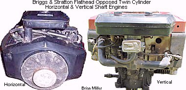 FYI - Some people confuse
a vertical shaft engine with a horizontal shaft engine, and vice-verse. They
think being the piston travels vertically (side to side
ó) or horizontally (up and down
ô), that it's a vertical or horizontal
shaft engine. But it's the position of the crankshaft that determines
if it's a vertical or horizontal shaft engine. This is why they're called
a vertical SHAFT engine and horizontal SHAFT engine. Otherwise, they would
be called a vertical piston engine and horizontal piston engine, which is
the wrong terminology. Anyway, the parts needed to convert a vertical shaft
opposed twin cylinder flathead B&S engine into a horizontal shaft model
are as follows. The parts listed below Ê
must come off a horizontal shaft opposed twin cylinder flathead B&S engine.
FYI - Some people confuse
a vertical shaft engine with a horizontal shaft engine, and vice-verse. They
think being the piston travels vertically (side to side
ó) or horizontally (up and down
ô), that it's a vertical or horizontal
shaft engine. But it's the position of the crankshaft that determines
if it's a vertical or horizontal shaft engine. This is why they're called
a vertical SHAFT engine and horizontal SHAFT engine. Otherwise, they would
be called a vertical piston engine and horizontal piston engine, which is
the wrong terminology. Anyway, the parts needed to convert a vertical shaft
opposed twin cylinder flathead B&S engine into a horizontal shaft model
are as follows. The parts listed below Ê
must come off a horizontal shaft opposed twin cylinder flathead B&S engine.
To install a opposed twin cylinder engine into a Cub Cadet garden tractor, on the narrow and wide frame Cubs, the frame rails will need to be cut down for installation of an opposed twin cylinder engine. But the spread frame Cubs are made for the opposed twin cylinder engine. And a V-twin engine will fit in virtually into any Cub Cadet garden tractor with few modifications. The frame rails shouldn't have to be altered either. Go here for an example of a V-twin that was installed in a wide frame Cub Cadet garden tractor: http://www.smallenginewarehouse.com/RepowerItems.asp?Brand=Cub%20Cadet&Model=1000.
How to Reinforce OEM OHV V-Twin Aluminum Block Engines to Prevent from Cracking or Breaking for High Performance/Open RPM Competition Pulling - [Top of Page]
A Kohler, Kawasaki, etc., V-twin engine with a 2-barrel carburetor with separate/individual intake runners, one barrel can lean out due to a partially clogged main jet, while the other barrel will provide plenty of fuel to the cylinder. The cylinder with the partially clogged jet will run hotter than normal, which can cause the piston rings to lose their expansion against the cylinder wall. The cylinder head can also warp and valve seats can loosen and fall out of their counterbore. This is why most pullers prefer to use a single barrel carburetor.
Also, most OEM OHV V-twin aluminum engine blocks will "bend and twist" just a few thousands of an inch when hot and under competition pulling stress and strain. This cause them to lose valuable compression because the valves become unseated and the piston rings lose partial contact against the cylinder wall. Not to mention the main radial ball bearings are also put into a bind on the crankshaft when under the stress and strain of pulling. Click the photo below to see what can happen to a Kohler (117hp) Command V-twin engine when used for pulling. [The Brute Pulling and Breaking - YouTube] (Watch the video to the end.)
When building an OEM aluminum block V-twin engine for competition pulling, and to prevent the crankcase and/or closure plate from cracking or breaking under severe strain, do not install a gasket between the crankcase and closure plate (end cover)! Instead, apply a thin bead of clear RTV silicone adhesive sealant between the crankcase and closure plate, then tighten the bolts to the factory recommended torque value. The absence of a gasket will allow for direct metal-to-metal contact, which keeps the fastening bolts securely tight and this creates a "bond" between the two metals, which strengthens/reinforces the crankcase and closure plate with each other to prevent it/them from cracking or breaking when under severe strain. This is the same reason an oil pan gasket is not recommended for a single cylinder K-series and Magnum competition pulling engine. By the way - it's best to use Clear RTV Silicone Adhesive Sealant for three reasons: Gaskets don't always seal the imperfections and irregularities between two mating metals, especially thin metal covers; being Clear RTV Silicone Adhesive Sealant is an adhesive or glue, it bonds parts together, forming a leak-proof seal; and being it's clear, it makes for a clean and professional-looking repair job. When applied sparingly, it can't be easily seen or noticed between the parts. Also, engine heat has very little effect on silicone rubber. It can withstand up to 2,500 degrees heat.
Referring to the photos below Ê, what caused the closure plate (end cover) and crankshaft to break is because a gasket was used between the crankcase (engine block) and closure plate. The bolts securing the closure plate to the crankcase made the closure plate totally dependent on the bolts only for rigidity, and the gasket acted as a cushion. When the high RPM/high compression engine was under severe pulling stress, this placed tremendous amount of strain and movement of the closure plate. The gasket allowed the closure plate to "move around" a few thousandths of an inch against the bolts independently of the crankcase. When the crankcase and closure plate were "moving around" against each other, this caused the gasket to "flatten out" and become thinner, which allowed the bolts to loosen slightly. The bolts did not rotate counterclockwise to loosen, they simply lost their torque or "tightness" against the metal. If no gasket was used, and a thin bead of clear RTV silicone adhesive sealant was applied between the crankcase and closure plate (and the necessary thrust washers and shims installed to control the crankshaft and camshaft clearance/end-play), and the bolts torqued to specs, the closure plate would have had metal to metal contact and became more or less "integrated" with the crankcase (with the silicone to seal the imperfections and irregularities between the two mating surfaces), this would have allowed the closure plate to be much more rigid and less prone to breakage. Some non-professional/amateur engine builders are die-hard believers in the use of gaskets for the entire engine, and this is the ultimate result in their way of thinking.

Cast iron engine blocks on the other hand hold their shape a lot better when
hot and under stress. Aluminum engines work best for conditions that doesn't
place them in a lot of stress. Such as ATVs, racing go-karts, racing lawn
mowers, etc. Because there's fresh air moving over the engine, keeping the
metal cool, and the block isn't being strained by the vehicle pulling a heavy
load. This is why the cast iron block Kohler engines work best for competition
pulling. We think that Kohler is the best engine for pulling. They're the
old school "Chevrolet" of competition pulling engines
(you know what I mean
 ). Because cast iron is able to "hold
its shape," handle high operating temperatures, severe stress, high compression
and at open RPM. This is why most riding mowers, lawn tractors and lawn and
garden tractors have an aluminum block engine. And most garden tractors have
a cast iron block engine.
). Because cast iron is able to "hold
its shape," handle high operating temperatures, severe stress, high compression
and at open RPM. This is why most riding mowers, lawn tractors and lawn and
garden tractors have an aluminum block engine. And most garden tractors have
a cast iron block engine.
In addition, on the cast iron block single cylinder Briggs & Stratton and Tecumseh engines, the valve stems are parallel to the cylinder. This means that the valve heads set further away from the piston. And in the cast iron block single cylinder Kohler engines, the valve heads set closer to the piston (valve stems and lifters are angled 4°). Therefore, the other engines can't build up as much compression as Kohler engines can. Plus, they can't flow as much air in and out of the combustion chamber at open RPM, like Kohler engines can.
If the crankcase is building up too much air pressure in an OHV aluminum block engine, and blowing oil out the crankcase breather, then chances are, the cylinder heads are warped. This is a common thing with virtually all seasoned OHV aluminum block engines. The heads become warped between the pushrods because there's no head bolt there to apply pressure against the head gasket. To fix the warped heads, remove the heads, resurface them on a wide, flat belt- or disc-sander/grinder to remove the any warpage and restore flatness. Be sure to clean the metal fragments from the heads, deburr the edge of the combustion chamber to prevent any hot spots, install the heads with new head gaskets, torque the head bolts to specs, and readjust the valves. Being the metal has already taken shape from normal engine heat for the first time, the heads should not warp again for the life of the engine.
How to Use Two Engines in a Competition Garden Pulling Tractor -
The alternative to using a V-twin engine in a Cub Cadet competition garden pulling tractor is to use two light-weight aluminum block horizontal shaft single cylinder engines installed side by side with the flywheels facing forward instead. The frame of the tractor would need to be modified and heavily reinforced to support the engines, too. With two engines installed inline, one behind the other with the flywheel on each engine facing forward, with the crankshafts direct-coupled together, it'll be better to use the 31-15.15x15 pulling tires for more weight distribution for better traction. If the engines are installed reversed, the rear end carrier/ring gear in the transaxle would need to be "flipped" so the tractor will drive forward in the forward gears. The reason it'll be better for the engines to be side by side is because less weight will be on the front of the tractor, and more weight will be transferred to the rear tires when pulling for netter traction. For the side by side engines to drive the tractor, a heavy duty centrifugal clutch (with #40 sprocket teeth) would need to be installed on each engine crankshaft, with two #40 sprockets, one offset of the other, installed on the driveshaft, which will act as a mainshaft. Pillow block bearings will need to be used to support the driveshaft. The OEM-type of Cub Cadet garden tractor clutch setup cannot be used. The centrifugal clutches will act like a stall torque converter, much like in an automotive automatic transmission. The centrifugal clutches will engage around 2,000 RPM, and will lock up above 2,600 RPM more or less. The centrifugal clutches will disengage at idling speed (1,200 RPM [±75 RPM]), and the carburetors can be easily adjusted or synchronized without one running engine interfering with the other, unlike in a "direct-coupled together" configuration.
How to Convert the Kohler Command Pro V-Twin Vertical Shaft Engine into a Horizontal Shaft Engine -
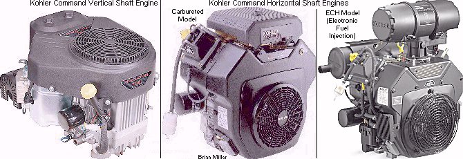 The parts needed to
convert a Kohler Command Pro V-Twin vertical shaft engine into a horizontal
shaft engine are as follows. The parts listed below
Ê must come off a horizontal shaft Kohler
Command Pro V-Twin engine.
The parts needed to
convert a Kohler Command Pro V-Twin vertical shaft engine into a horizontal
shaft engine are as follows. The parts listed below
Ê must come off a horizontal shaft Kohler
Command Pro V-Twin engine.
FYI - The big price difference in horizontal vs vertical shaft engines is based on supply and demand. Equipment that require a vertical shaft engine are more plentiful, such as lawn mowers, riding mowers, etc. Therefore, whenever small engine equipment use a vertical shaft engine, this brings down the cost of production of the engine. Equipment that require a horizontal shaft engine are rare (nowadays). Therefore, the price on these engines are higher. Some manufacturers convert their products, such as logsplitters, for use with a vertical shaft engine. This allow them to sell their equipment at a lower price, due to the lower cost engine.
When rebuilding any used engine (also known as
a
"seasoned" engine), especially an aluminum block engine,
as the crankcase and cylinder head(s) get hot for the very first time (new
engine), they bend, twist and warp a few thousands of an inch due to normal
operating heat. This is called block (and related parts) warping. In other
words, combustion heat cause the metal to "take shape." This is normal for
all new engines, small engines, automotive, etc., gas or diesel, air-cooled
or liquid-cooled, and is unavoidable. So when rebuilding a used engine, have
the cylinder head and other parts measured with a straight edge. And if they're
warped, have them machined flat or resurfaced on a wide, flat
belt- or disc-sander/grinder to remove any warpage
and restore flatness. This will ensure 100% gasket sealing. And if the cylinder
bore(s) are out of round, have them bored to the next oversize to ensure
a 100% piston ring seal. When the parts get hot the second time (due to normal
operating heat), they should not bend, twist or warp again. This is a one
time deal.
How to Determine if an Engine Needs Rebuilding - (This information applies to most small engines, automotive, farm and industrial equipment engines.)

First of all, oil usage is controlled by the "snugness" of the piston in the cylinder or how cool the engine operates. The below Ê are things that can cause an engine to burn oil:
Either or a combination of the above È will definitely cause an engine to overheat (except without an air filter), causing the rings to lose their tension against the cylinder wall, resulting in the oil being burned. We have seen all of these things happen to a good engine many times.
 If someone tells you that an
older cast iron block Kohler engine isn�t worth repairing or rebuilding and
repowering your garden tractor small motorized vehicle or small engine equipment
with a new engine is the way to go, then they obviously is lying to you,
don't know much about older Kohler engines or is trying to make a lot of
money by selling you a new repower kit. Most cast iron block Kohler engines
will last 30-40 years before they need rebuilding. No small engine made nowadays
will last that long. And if they do, chances are they are not worth rebuilding.
The old cast iron Kohler engines can be rebuilt multiple times, as long as
everything in it is rebuildable and not damaged beyond reuse. We think the
older Kohler engines are the old school "Chevrolet" of small engines
(you know what I mean
). If you do find an older Kohler
engine, despite the condition it's in, just remember that it's worth repairing
or rebuilding. It'll be like restoring an old Chevrolet
(again, you know what I mean
).
If someone tells you that an
older cast iron block Kohler engine isn�t worth repairing or rebuilding and
repowering your garden tractor small motorized vehicle or small engine equipment
with a new engine is the way to go, then they obviously is lying to you,
don't know much about older Kohler engines or is trying to make a lot of
money by selling you a new repower kit. Most cast iron block Kohler engines
will last 30-40 years before they need rebuilding. No small engine made nowadays
will last that long. And if they do, chances are they are not worth rebuilding.
The old cast iron Kohler engines can be rebuilt multiple times, as long as
everything in it is rebuildable and not damaged beyond reuse. We think the
older Kohler engines are the old school "Chevrolet" of small engines
(you know what I mean
). If you do find an older Kohler
engine, despite the condition it's in, just remember that it's worth repairing
or rebuilding. It'll be like restoring an old Chevrolet
(again, you know what I mean
).
 Before the engine is removed
from the tractor or equipment and disassembled (this is much easier to do
on a platform work table),
first, remove the cylinder head and observe the top of the piston. If it's
100% coated with carbon, then the piston rings are in good condition. But
if there's oil present and some of the carbon is washed away around the edges,
this means that the rings and piston are worn and need replacing, or the
cylinder needs to be rebored for installation of a new oversized piston and
rings assembly. But if the cylinder is max'd out at .030" and worn, it can
be either be bored for an aftermarket (made to OEM specs) .040" oversize
piston and rings assembly (OEM Kohler-replicated; only for the K301, M12,
K321, M14, K341, M16 and K361 [OHV] engines), or sleeved
back to STD size for all other Kohler engines. See my list of STD
size, .010", .020", .030" and .040" oversize piston and rings further down
in this web site Ê.
Before the engine is removed
from the tractor or equipment and disassembled (this is much easier to do
on a platform work table),
first, remove the cylinder head and observe the top of the piston. If it's
100% coated with carbon, then the piston rings are in good condition. But
if there's oil present and some of the carbon is washed away around the edges,
this means that the rings and piston are worn and need replacing, or the
cylinder needs to be rebored for installation of a new oversized piston and
rings assembly. But if the cylinder is max'd out at .030" and worn, it can
be either be bored for an aftermarket (made to OEM specs) .040" oversize
piston and rings assembly (OEM Kohler-replicated; only for the K301, M12,
K321, M14, K341, M16 and K361 [OHV] engines), or sleeved
back to STD size for all other Kohler engines. See my list of STD
size, .010", .020", .030" and .040" oversize piston and rings further down
in this web site Ê.
The cap on a connecting rod is precision machined (honed) to form an absolute perfect circle to match the rod it is installed on. If a cap is swapped from one rod to another and then installed in an engine, chances are, the rod will be too tight or too loose on the crank journal. If an oil dipper breaks off the cap, another cap can be used on the rod, but the cap (and rod) would need to be precision honed to form a perfect circle again.
Now Move to the Valves. How to Test for Leaking or Burnt Valves - [Top of Page]
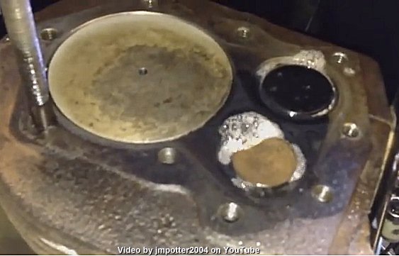 The appearance of used
valves in an engine are like women, you can't always go by looks. In other
words, the appearance of valves in an engine won't tell you if they're sealing
in compression 100% or not. A "leak down test" with a gauge will only show
you if the combustion chamber has a leak. So the real way to test for leaking
valves on virtually any 4-cycle flathead engine, first of all, both valve
clearances should be checked and adjusted to specs, if needed, before performing
this test. Now with the carburetor, muffler or exhaust pipe and [flathead]
cylinder head removed, and with the piston positioned exactly at top dead
center (TDC) on the compression stroke (this is when both valves are fully
closed), apply
Liquid Wrench (spray) or
WD-40 around each valve and with a rag/shop towel wrapped
around an
air blow gun nozzle with the rag/shop towel snug against
the port to seal in the air pressure so maximum pressure will be applied
to the valves, apply 150± PSI compressed air through the exhaust and
intake ports. To perform this same test on an over head valve (OHV) engine,
the cylinder head will need to be removed and [lightly] clamped in a bench
vise. Anyway, if multiple bubbles form (slight leakage) and/or if the liquid
gets "blown out" around the valves (severe leakage) when applying the air
pressure, this means the valves are leaking or burnt and a
professional valve job is required.
Performing a valve job restores full compression, which will allow the engine
to start quicker, idle smoothly, rev up with no hesitation, produce lots
of power, and run for a long time without stalling or dying (when the ignition
timing and carburetor adjustments are set correctly, too). Do not use soapy
water to perform this test because the water content will cause the steel
and cast iron to rust if not immediately cleaned off and thoroughly dried.
The "bubbles" part of this test won't be accurate with freshly reground valves
and seats (fresh valve job) because the valves haven't worn into the seats
yet to form a perfect seal. This is known as valve wear-in or more commonly
as engine break-in. Click the photo to the right -> to watch how this
test is performed on
YouTube.
By the way - The video shows both valves fully closed with the piston positioned
at top dead center (TDC) on the compression stroke. And if you're wondering,
the Automatic Compression Release (ACR) only works with the exhaust valve.
It doesn't hold the exhaust valve open when the piston is at top dead center
(TDC) on the compression stroke. It only works when the piston is traveling
about halfway up in the cylinder just before it reaches top dead center (BTDC)
on the compression stroke. FYI - If you have a Kohler 7-16hp ACR camshaft
that was broke in two by a thrown connecting rod, save the spring off of
it. It can be used on another good cam that may not have one. Or if your
ACR spring places little or weak pressure against the flyweights/levers,
it can be re-bent or reshaped to its original condition to place sufficient
tension against the flyweights/levers.
The appearance of used
valves in an engine are like women, you can't always go by looks. In other
words, the appearance of valves in an engine won't tell you if they're sealing
in compression 100% or not. A "leak down test" with a gauge will only show
you if the combustion chamber has a leak. So the real way to test for leaking
valves on virtually any 4-cycle flathead engine, first of all, both valve
clearances should be checked and adjusted to specs, if needed, before performing
this test. Now with the carburetor, muffler or exhaust pipe and [flathead]
cylinder head removed, and with the piston positioned exactly at top dead
center (TDC) on the compression stroke (this is when both valves are fully
closed), apply
Liquid Wrench (spray) or
WD-40 around each valve and with a rag/shop towel wrapped
around an
air blow gun nozzle with the rag/shop towel snug against
the port to seal in the air pressure so maximum pressure will be applied
to the valves, apply 150± PSI compressed air through the exhaust and
intake ports. To perform this same test on an over head valve (OHV) engine,
the cylinder head will need to be removed and [lightly] clamped in a bench
vise. Anyway, if multiple bubbles form (slight leakage) and/or if the liquid
gets "blown out" around the valves (severe leakage) when applying the air
pressure, this means the valves are leaking or burnt and a
professional valve job is required.
Performing a valve job restores full compression, which will allow the engine
to start quicker, idle smoothly, rev up with no hesitation, produce lots
of power, and run for a long time without stalling or dying (when the ignition
timing and carburetor adjustments are set correctly, too). Do not use soapy
water to perform this test because the water content will cause the steel
and cast iron to rust if not immediately cleaned off and thoroughly dried.
The "bubbles" part of this test won't be accurate with freshly reground valves
and seats (fresh valve job) because the valves haven't worn into the seats
yet to form a perfect seal. This is known as valve wear-in or more commonly
as engine break-in. Click the photo to the right -> to watch how this
test is performed on
YouTube.
By the way - The video shows both valves fully closed with the piston positioned
at top dead center (TDC) on the compression stroke. And if you're wondering,
the Automatic Compression Release (ACR) only works with the exhaust valve.
It doesn't hold the exhaust valve open when the piston is at top dead center
(TDC) on the compression stroke. It only works when the piston is traveling
about halfway up in the cylinder just before it reaches top dead center (BTDC)
on the compression stroke. FYI - If you have a Kohler 7-16hp ACR camshaft
that was broke in two by a thrown connecting rod, save the spring off of
it. It can be used on another good cam that may not have one. Or if your
ACR spring places little or weak pressure against the flyweights/levers,
it can be re-bent or reshaped to its original condition to place sufficient
tension against the flyweights/levers.
Performing a Compression Test with a Compression Tester or Leak Down Tester -
 A compression test shows how
much air within the combustion chamber is "squeezed" or "compressed," resulting
in the P.S.I. of pressure. But a leak down test shows how long the combustion
chamber can sustain air pressure within a period of time. A compression test
is performed dynamically with the throttle plate in the wide open position,
all spark plugs removed (in a multi-cylinder engine) and the engine cranking
over at full speed. But a leak down test is performed statically with the
(or each) piston positioned at 0º TDC on the compression stroke and
engine not cranking over. On a Kohler engine, with the piston positioned
exactly at 0º Top Dead Center (0º TDC) on the compression stroke,
the automatic compression release (ACR) mechanism allows the exhaust valve
to fully close, then a compression test can be performed with a
leak down tester. But the ACR effects a compression test
when performed with a
compression tester. 0º TDC on the compression stroke
is when the piston is at its very top in the cylinder with both valves fully
closed. 0º TDC is also when the T mark on the flywheel
is aligned exactly with the raised boss on the bearing plate (engines with
a gear starter), or with centered of the sight hole on the side of the flywheel
shroud or on the rear of the bearing plate (engines with a starter/generator),
and the initial alignment can be seen with a flashlight through the sight
hole in the OEM bearing plate. But the best way to determine if an engine
needs to be rebuilt is to remove the cylinder head and look at the edge of
the piston. If the carbon deposits is washed away or partially absent from
the top of the piston, this means the piston and rings are worn, and the
engine needs to be rebuilt. YouTube video link:
Does
the length of the hose on a compression tester matter?
A compression test shows how
much air within the combustion chamber is "squeezed" or "compressed," resulting
in the P.S.I. of pressure. But a leak down test shows how long the combustion
chamber can sustain air pressure within a period of time. A compression test
is performed dynamically with the throttle plate in the wide open position,
all spark plugs removed (in a multi-cylinder engine) and the engine cranking
over at full speed. But a leak down test is performed statically with the
(or each) piston positioned at 0º TDC on the compression stroke and
engine not cranking over. On a Kohler engine, with the piston positioned
exactly at 0º Top Dead Center (0º TDC) on the compression stroke,
the automatic compression release (ACR) mechanism allows the exhaust valve
to fully close, then a compression test can be performed with a
leak down tester. But the ACR effects a compression test
when performed with a
compression tester. 0º TDC on the compression stroke
is when the piston is at its very top in the cylinder with both valves fully
closed. 0º TDC is also when the T mark on the flywheel
is aligned exactly with the raised boss on the bearing plate (engines with
a gear starter), or with centered of the sight hole on the side of the flywheel
shroud or on the rear of the bearing plate (engines with a starter/generator),
and the initial alignment can be seen with a flashlight through the sight
hole in the OEM bearing plate. But the best way to determine if an engine
needs to be rebuilt is to remove the cylinder head and look at the edge of
the piston. If the carbon deposits is washed away or partially absent from
the top of the piston, this means the piston and rings are worn, and the
engine needs to be rebuilt. YouTube video link:
Does
the length of the hose on a compression tester matter?
How to Perform an Accurate Compression Test with a Compression Tester on a Stock or High-Performance Small Engine -
 Only the Kohler K-series and
Magnum single cylinder engines have a compression release mechanism on the
camshaft. And due to their low compression, the Kohler opposed twin cylinder
engine models KT17 (first design), KT17 Series II, KT19 (first design), KT19
Series II, KT21, MV16, M18, MV18, M20 and MV20 do not have a compression
release, nor do they need one. Anyway, an accurate compression reading can't
be performed on an engine with an unaltered OEM camshaft due to the compression
release mechanism on one of the cam lobes. Depending on the make and model
of engine, the compression release is either a small hump (early B&S,
various Tecumseh's, etc.), mechanical lever/pin (newer B&S, Kohler, some
Tecumseh, etc.) on one of the camshaft lobes that holds either the intake
or exhaust valve open about .050" while the piston is traveling halfway up
in the cylinder on the compression stroke, or a tiny hole drilled through
the exhaust seat next to the exhaust valve on various very early Tecumseh
engines. On OEM camshafts with a working compression release mechanism and
if the valve clearances are adjusted to specs, the compression release relieves
about half the compression air from the combustion chamber at cranking speed.
This is so the engines with fixed advanced ignition timing will start easier.
When attempting to start an engine with fixed advanced ignition timing, if
the compression release isn't working or if the valve (with the compression
release) have too much stem-to-lifter clearance (out of adjustment), the
engine will "kick back" every time. "Kick back" occurs when the crankshaft
suddenly and violently rebounds or rotates in the opposite direction, which
is could bend or break the starter armature shaft or the aluminum starter
housing.
Only the Kohler K-series and
Magnum single cylinder engines have a compression release mechanism on the
camshaft. And due to their low compression, the Kohler opposed twin cylinder
engine models KT17 (first design), KT17 Series II, KT19 (first design), KT19
Series II, KT21, MV16, M18, MV18, M20 and MV20 do not have a compression
release, nor do they need one. Anyway, an accurate compression reading can't
be performed on an engine with an unaltered OEM camshaft due to the compression
release mechanism on one of the cam lobes. Depending on the make and model
of engine, the compression release is either a small hump (early B&S,
various Tecumseh's, etc.), mechanical lever/pin (newer B&S, Kohler, some
Tecumseh, etc.) on one of the camshaft lobes that holds either the intake
or exhaust valve open about .050" while the piston is traveling halfway up
in the cylinder on the compression stroke, or a tiny hole drilled through
the exhaust seat next to the exhaust valve on various very early Tecumseh
engines. On OEM camshafts with a working compression release mechanism and
if the valve clearances are adjusted to specs, the compression release relieves
about half the compression air from the combustion chamber at cranking speed.
This is so the engines with fixed advanced ignition timing will start easier.
When attempting to start an engine with fixed advanced ignition timing, if
the compression release isn't working or if the valve (with the compression
release) have too much stem-to-lifter clearance (out of adjustment), the
engine will "kick back" every time. "Kick back" occurs when the crankshaft
suddenly and violently rebounds or rotates in the opposite direction, which
is could bend or break the starter armature shaft or the aluminum starter
housing.
On various B&S, Kohler models K90/K91, K141, K160/K161, L160/L161, L181, K181 and M8, some Tecumseh, etc. engines without adjustable lifters, but with an automatic compression release (ACR), there is no way to perform an accurate compression test with a compression tester. All that can be done to test the compression is rotate the flywheel quickly by hand in the opposite direction of normal engine rotation. If it rebounds sharply, the engine has adequate compression.
There are two ways to perform an accurate compression test with a compression tester on the Kohler K-series and Magnum engine models K241, M10, K301, M12, K321, M14, K341, M16 and K361:
To obtain an accurate compression pressure reading, perform the test with a fully charged battery, a starter that's in good condition and the throttle in the wide open position. Or with pull rope engines, place the throttle in the wide open position. When performing a compression test with a gauge on an air-cooled engine, keep in mind that, depending on how the engine is built, the compression ratio or the compression pressure can vary from one engine to another. It depends on the size of the bore and stroke, the volume of the combustion chamber in the cylinder head, if the camshaft has a compression release or not and how much duration the cam lobes have. If a cam has a compression release mechanism, being approximately half the compression is released from the combustion chamber at cranking speed, the compression reading will be cut approximately in half.
When performing a compression test with a gauge on a Kohler engine in good condition under full compression, stock camshaft and no compression release, the K241 and M10 engines can range from 98 to 150 PSI. On the K301 and M12 engines, it can range from 112 to 170 PSI. On the K321 and M14 engines, it can range from 120 to 190 PSI. And the K341 and M16 engines, it can be from 127 up to 192 PSI. The range of the compression pressures depends on the type of cylinder head used. If the camshaft has a working compression release, it will relieve about half the compression pressure (PSI).
And cranking speeds, a long duration cam will relieve some of the combustion chamber pressure, resulting in a lower than normal reading. The more the duration, the lower the reading. Calculate the reading with the duration of the cam in the engine against the duration of a stock OEM cam. Example: If the compression pressure is 100 PSI, multiple 100 by 285 (duration of cam that's in the engine) and then divide the answer by 223 degrees (duration of a stock OEM cam), which gives 128 PSI.
Now for the engine problem: Air from the leak down test came from inside the crankcase due to the gaps in the piston rings. As the engine warms up, due to friction and combustion heat, the rings expand and the gaps close up. The dark colored oil is from partial incomplete burning of the gas that went past the ring gaps into the crankcase because the engine couldn't reach its normal operating temperature due to bad valves. If an engine has an oil pump with an oil filter adapter and oil filter, the oil gets filtered from dirt and metal fragments, preventing excessive wear to vital moving parts inside the engine, but the oil filter will not filter out the dark colored liquid by-products from incomplete burning of the fuel that's mixed with the oil. The by-products will eventually thin out the oil or lower the viscosity, causing excessive wear to the internal moving parts. I've repaired many engines when the piston rings are in good condition, but the valve faces and seats was warped. After performing a professional valve job, regrinding both valve faces and seats, and setting the correct valve clearances, and perhaps installing new guides, customers told A-1 Miller's that their engine ran better and produce more power than when it was new. With a professional valve job performed and with everything else right on the engine, the engine should start quicker, idle smoother, warm up faster, accelerate to full RPM without hesitation, run at normal operating temperature, and burn the fuel more thoroughly, which will allow the crankcase oil to stay cleaner longer.
To remove the engine from a typical IH Cub Cadet garden tractor, first disconnect the battery negative terminal and disconnect all the wiring from the engine and fuel line if the gas tank is separate from the engine. Then remove the PTO clutch engaging linkage, remove the engine mounting bolts, then slide the engine forward so it'll clear the clutch disc or driveshaft, then lift the engine out of the tractor. This is much easier to do on a platform work table.
Now remove the oil pan and connecting rod cap. Observe the rod cap for scoring or burning. Replace or repair it if necessary. Also, the crankshaft journal may be worn and if it is, it will need to be reground to the next undersize. And have the crank journal measured or "mic'd" with an outside precision micrometer to determine if it's excessively worn. Dial or digital calipers can't measure a crank journal or anything else as accurately as a micrometer can. The micrometer measures more accurately because the beam section don't flex as much. Anyway, if the journal is worn, it can be reground to .010" and a .010" undersize plain aluminum [bearing] surface connecting rod can be used or the original rod can be bored for installation of .010" replaceable bearing inserts. But if the journal needs to be reground to .020" or .030", the rod will need to be bored for installation of matching bearing inserts. The only OEM rods available without a bearing are STD size and .010" undersize.
If the cylinder wall is badly scored or tapered, have it bored to the next oversize. The only pistons available for a stock engine are STD, .010", .020" and .030". But if the cylinder is max'd out at .030" and worn, it can be either be bored for an aftermarket (made to OEM specs) .040" oversize piston and rings assembly (OEM Kohler-replicated; only for the K301, M12, K321, M14, K341, M16 and K361 [OHV] engines), or sleeved back to STD size for all other Kohler engines. See my list of STD size, .010", .020", .030" and .040" oversize piston and rings further down in this web site Ê. But if building an engine for more power, don't have the cylinder bored to a maximum of .030" if it doesn't need it. Because a .030" overbore won't necessarily give an engine more power. Having a longer crankshaft stroke increases the power.
I don't offer any engine rebuild kits for three reasons: 1. There are certain parts included in most kits that is not needed or required for the rebuild; 2. If the cylinder in an engine needs to be bored oversize, most rebuild kits don't come with an oversize piston and rings assembly, and; 3. Most entire engine rebuild kits cost more than if each part that's included in the kits were purchased individually, so the rebuild kit would really be a waste of money. So actually, the best thing to do is completely disassemble your engine, clean all the parts, inspect the valves for burning or being bent, mic the crank journal for wear or scoring, and observe the cylinder wall for wear or scoring to determine which internal engine parts are required for a professional rebuild.
| The following basic specialty tools are required to disassemble, reassemble and rebuild a single- or opposed twin-cylinder Kohler engine. Most of these tools are available at auto parts stores and online. | |
|
|
 More sophisticated
equipment, tooling and machinery is required to perform specially machine
work on certain engine components, such as: boring bar and/or cylinder hone
to bore the cylinder oversize, crankshaft grinding machine to regrind the
crankshaft journal(s); valve face grinding machine to reground the valve
faces; valve seat cutter or grinder set to recut or reground the valve seats;
milling machine to bore the connecting rod for installation of replaceable
bearing inserts; etc. In most cases, the original
valves can be reground. But if the valve(s) are severely worn or the face
is burned away (especially the exhaust valve), it will need to be machined
and/or replaced with a used valve in good condition or a new valve. A-1
Miller's offers the machine work and the parts required to perform a complete
and professional engine rebuild. Most common engine rebuild parts required
are: piston and rings, connecting rod, valves, gaskets w/oil seals, carburetor
kit and complete tune up kit. More sophisticated
equipment, tooling and machinery is required to perform specially machine
work on certain engine components, such as: boring bar and/or cylinder hone
to bore the cylinder oversize, crankshaft grinding machine to regrind the
crankshaft journal(s); valve face grinding machine to reground the valve
faces; valve seat cutter or grinder set to recut or reground the valve seats;
milling machine to bore the connecting rod for installation of replaceable
bearing inserts; etc. In most cases, the original
valves can be reground. But if the valve(s) are severely worn or the face
is burned away (especially the exhaust valve), it will need to be machined
and/or replaced with a used valve in good condition or a new valve. A-1
Miller's offers the machine work and the parts required to perform a complete
and professional engine rebuild. Most common engine rebuild parts required
are: piston and rings, connecting rod, valves, gaskets w/oil seals, carburetor
kit and complete tune up kit. |
|
How Replaceable Lead-Coated
Bearing Inserts (Rod Bearings) Protect An Engine -
[Return to previous paragraph]
Due to the lack of or an insufficient amount of oil in the crankcase, or at open RPM with 100% petroleum oil, an ordinary aluminum bearing surface connecting rod will likely to burn the rod and score the crank journal, and if the engine is ran long enough with a loose rod, the rod will likely break, possibly destroying the engine block. But an engine with lead-coated bearing inserts, if the oil is contaminated with dirt or metal shavings, or if the engine is ran low on oil, out of oil or if the wrong viscosity is used (too thin of oil for warm weather conditions or for high performance use), as the bearing inserts wear, they won't score the crank journal like an ordinary plain aluminum bearing surface rod will.
 High RPM
bearing inserts are made with three layers
of material: an outer steel shell for rigidity, a copper underlayment, and
a thin inner layer of lead alloy that makes contact with the crank journal.
The lead cushions the extreme pressure and cools the crank journal and rod
from excessive heat from high RPM engine operation. (When
used with conventional/petroleum motor oil.) The lead also allows for
small fragments of metal to become embedded into it to prevent scoring or
excessive wear of the crank journal. All lead-coated bearing inserts are
considered high performance and can withstand very high RPM, and adds durability
and toughness to the connecting rod. These are most commonly used in most
applications.
High RPM
bearing inserts are made with three layers
of material: an outer steel shell for rigidity, a copper underlayment, and
a thin inner layer of lead alloy that makes contact with the crank journal.
The lead cushions the extreme pressure and cools the crank journal and rod
from excessive heat from high RPM engine operation. (When
used with conventional/petroleum motor oil.) The lead also allows for
small fragments of metal to become embedded into it to prevent scoring or
excessive wear of the crank journal. All lead-coated bearing inserts are
considered high performance and can withstand very high RPM, and adds durability
and toughness to the connecting rod. These are most commonly used in most
applications.
 Low RPM (up to 4, 000 RPM)
bearing inserts on the other hand, have only
two layers: the outer steel shell and an inner aluminum alloy layer/coating
that makes contact with the crank journal. This type of bearing inserts for
Kohler engines are rare, and should NEVER be used in a open RPM engine because
aluminum cannot handle heat as well as lead. Aluminum bearing inserts (used
with various newer automotive engine steel rods) are not high performance.
Aluminum bearing inserts have no heat-resistant lead coating and when used
in a open RPM engine with conventional/petroleum motor oil, and even with
the additional .001" oil clearance, the bearing will likely burn on the crank
journal, resulting in connecting rod failure, which could damage or destroy
the engine block. Therefore, these type of bearing inserts should ONLY be
used in a 4,000± RPM governed engine with conventional/petroleum motor
oil, or can be used with full synthetic motor oil in a
full pressure oil pump lubricating system.
Low RPM (up to 4, 000 RPM)
bearing inserts on the other hand, have only
two layers: the outer steel shell and an inner aluminum alloy layer/coating
that makes contact with the crank journal. This type of bearing inserts for
Kohler engines are rare, and should NEVER be used in a open RPM engine because
aluminum cannot handle heat as well as lead. Aluminum bearing inserts (used
with various newer automotive engine steel rods) are not high performance.
Aluminum bearing inserts have no heat-resistant lead coating and when used
in a open RPM engine with conventional/petroleum motor oil, and even with
the additional .001" oil clearance, the bearing will likely burn on the crank
journal, resulting in connecting rod failure, which could damage or destroy
the engine block. Therefore, these type of bearing inserts should ONLY be
used in a 4,000± RPM governed engine with conventional/petroleum motor
oil, or can be used with full synthetic motor oil in a
full pressure oil pump lubricating system.
 Another low RPM (up to 4,000±
RPM) bearing inserts is available in an unmachined
.060" undersize. A-1 Miller's have a limited supply of these in stock, and
can be bored and finish-honed for use with a .040" or .050" undersize crank
journal. The unmachined .060" bearing inserts
can be used with a .060" undersize crank journal. This particular bearing
inserts don't have the protective inner lead-coating. It has a bronze inner
layer, which shouldn't be used in a open RPM competition pulling engine.
These type of bearing inserts too, just like the aluminum bearing inserts
above, should ONLY be used in a 4,000± RPM governed engine with
conventional/petroleum motor oil, or can be used with full
synthetic motor oil in a full pressure oil pump lubricating system.
Another low RPM (up to 4,000±
RPM) bearing inserts is available in an unmachined
.060" undersize. A-1 Miller's have a limited supply of these in stock, and
can be bored and finish-honed for use with a .040" or .050" undersize crank
journal. The unmachined .060" bearing inserts
can be used with a .060" undersize crank journal. This particular bearing
inserts don't have the protective inner lead-coating. It has a bronze inner
layer, which shouldn't be used in a open RPM competition pulling engine.
These type of bearing inserts too, just like the aluminum bearing inserts
above, should ONLY be used in a 4,000± RPM governed engine with
conventional/petroleum motor oil, or can be used with full
synthetic motor oil in a full pressure oil pump lubricating system.
A-1 Miller's Professional Repair Service - Bore YOUR Kohler scored or burnt connecting rod(s) and install replaceable lead-coated STD size, .010", .020", .030" undersize bearing inserts for a matching reground undersize crank journal. No need to purchase a new undersize rod. $65.00 for labor and bearing inserts, plus return shipping. A-1 Miller's professional crankshaft rod journal regrinding service also available.
Instead of boring a new or used connecting rod that has a smooth, undamaged bearing surface for installation of bearing inserts, a rod with a scored or burnt bearing surface can be bored out to make room for bearing inserts.
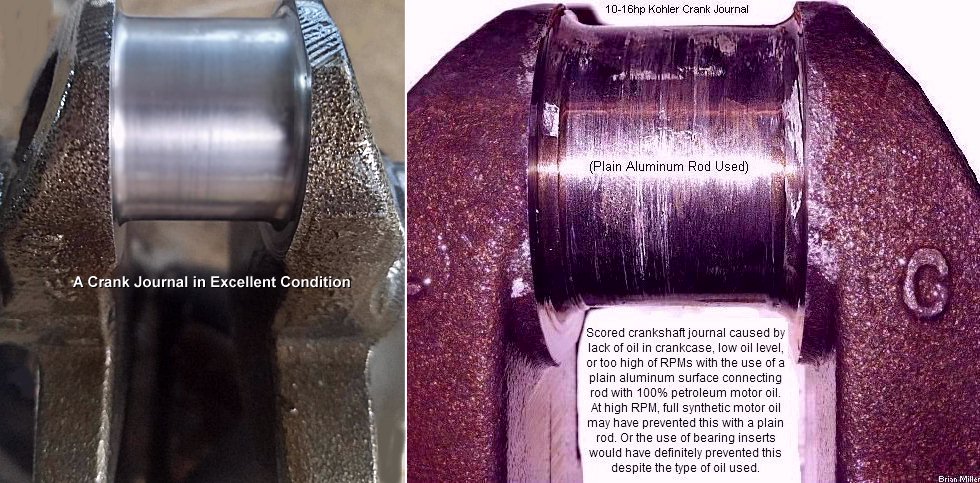

 The alternative to having a crank journal reground undersize
and using an undersize connecting rod is if the crank journal isn't deeply
scored and badly burnt from lack of lubrication or being over-revved, it
can be reground undersize until it's perfectly round again and if the original
rod also isn't deeply scored or badly burnt, it can be resized to fit the
reground odd-size journal with the factory recommended .0025" oil clearance.
This is useful for engines when a new replacement undersize rod is
cost-prohibitive or is not available. The rod would still be strong and should
last a long time. In most cases, it's cost-prohibitive to have a excessively
worn or deeply scored crank journal welded up and reground back to STD size.
NOTE - The maximum a connecting rod can be resized
to is .005" undersize. If it's resized more than .005", being the big hole
in the rod will be made excessively oblong or egg-shaped, which will allow
it to make less bearing surface contact around the crank journal after being
resized, due to the centrifugal force at 3,600 RPM, the big end of the rod
could become elongated (metal stretch) and might eventually knock and possibly
break.
The alternative to having a crank journal reground undersize
and using an undersize connecting rod is if the crank journal isn't deeply
scored and badly burnt from lack of lubrication or being over-revved, it
can be reground undersize until it's perfectly round again and if the original
rod also isn't deeply scored or badly burnt, it can be resized to fit the
reground odd-size journal with the factory recommended .0025" oil clearance.
This is useful for engines when a new replacement undersize rod is
cost-prohibitive or is not available. The rod would still be strong and should
last a long time. In most cases, it's cost-prohibitive to have a excessively
worn or deeply scored crank journal welded up and reground back to STD size.
NOTE - The maximum a connecting rod can be resized
to is .005" undersize. If it's resized more than .005", being the big hole
in the rod will be made excessively oblong or egg-shaped, which will allow
it to make less bearing surface contact around the crank journal after being
resized, due to the centrifugal force at 3,600 RPM, the big end of the rod
could become elongated (metal stretch) and might eventually knock and possibly
break.
To resize the rod so it'll fit to a few thousands of an inch smaller diameter crank journal, first, metal is removed from the mating end of the rod cap, then the cap is fasten to the rod. The big hole in the rod is now oblong or "egg shaped." Then the big hole in the rod is honed until it's .002" larger than the diameter of the crank journal. Honing reshapes the hole into a perfect circle again, only smaller in diameter. This works very well and it lasts as long as an ordinary STD size rod and crank journal. This can only be performed on a rod with a good bearing surface. It cannot be done on a burnt or heavily scored connecting rod because too much metal would need to be removed. Also, if the crank journal is worn beyond .030" undersize, it can be welded up and reground back to STD size. But in most cases, it's cost-prohibitive to have a worn or heavily scored crank journal welded up and reground back to STD size. There's lots of tricks that can be used to rebuild an engine. The rebuilt engine should last a long time, too.
No oil on the dipstick could mean the rod can burn on the crank journal, resulting in an engine knock, and an engine rebuild, or worse case sensorial, a hole in the side of the engine block. Always check and fill the oil (if needed) each time before the tractor/equipment is used just to be certain. Never assume the crankcase is still full of oil the last time you checked it. Because these little "air cooled" engines naturally run hot, especially during warm weather, which can force them to use oil from time to time.
The things that can cause connecting rod breakage are: (Added 5/15/24)
In most cases, when an engine is ran low on oil or out of oil, a rod with
worn bearing inserts will knock. If the rod
starts knocking, turn it off immediately and replace the damaged bearing
inserts, and then install the proper grade/weight of oil to the full level.
But sometimes after prolong running of the engine with worn bearing inserts,
the bore in the rod can become oblong or "egg-shaped" after taking a pounding
from worn bearing inserts. If this happens, a few thousandths of metal is
removed from the rod cap, the cap torqued to the rod, and then the big hole
in the rod can be precision-resized to the correct diameter for the bearing
inserts with a
connecting rod honing machine. If a new bearing is used
in a rod with an oblong hole, the bearing may fit too tight on the crank
journal, causing it to get hot while in use and possibly burn out from inadequate
oil clearance.  With bearing inserts,
the crank journal may also wear, but most likely not wear. It'll also be
wise to check the rod for stress cracks with a strong magnifying glass
With bearing inserts,
the crank journal may also wear, but most likely not wear. It'll also be
wise to check the rod for stress cracks with a strong magnifying glass
 or better yet, a powerful microscope.
Most of the time, cleaning the burnt aluminum from a crankshaft journal won't work because the journal itself may be scored or worn. Therefore, it'll be better to have it reground to the next undersize and install a matching undersize connecting rod. Or if an undersize rod or replaceable bearing inserts isn't available, have it reground undersize (to wherever it "cleans up") and resize the connecting rod for proper fit.
If a crank journal is worn smooth (not gouged or scored) and if the original plain aluminum bearing surface connecting rod, or even a new plain aluminum bearing surface rod is installed, the rod might knock, but it may last for several years under general lawn and garden use or for stock tractor pulling (4,000± RPM). However, the dangerous vibrating harmonics in the loose rod could cause stress cracks in the rod, eventually leading to rod failure. Bearing inserts cushions the extreme pressure the rod places on the worn journal, which lessens the harmonics, allowing the rod to last longer.
As long as the crankcase is full of oil (splash oil lubrication system) or adequate oil gets to the bearings (pressurized oil pump lubrication system), and as long as the bearing inserts have the proper oil clearance, they should hold up to unlimited engine RPM. If the correct velocity of oil is used, and if the crankcase oil is changed regularly, the bearing inserts should last the life of the engine. You'll also have more confidence knowing your connecting rod(s) has bearing inserts. Return to previous paragraph. È
Advertisement: | Click here to contact A-1 Miller's Performance Enterprises to place an order, send your parts for repairing, and/or for FREE professional and honest technical customer service assistance and support and payment options. If you need a part or parts that's not listed in this website, please contact A-1 Miller's and we'll see if we can get it at a reasonable price. | [Top of Page] Nowadays, prices are subject to change without notice.
 High Quality Bearing Inserts for Connecting Rods.
Can be used in Kohler engine models K241, M10, K301, M12, K321, M14,
K341, M16, K361, KT19 Series II, M20 and MV20. Available in STD size,
.010", .020", .030" and borable/resizable .060" (limited supply) undersizes.
NOTE: Rod must be bored-out (and notched) to make
room for bearing inserts. And a rod with a burnt aluminum surface can be
bored-out and bearing inserts can be installed.
Click here to learn
how bearing inserts protect an engine. Rods for the before mentioned
engines can be bored and notched to accept bearing
inserts. Even severely burnt, scored, or rods with a mismatched cap can
be bored for installation of bearing inserts. Only USA-made Clevite 77, Federal
Mogul or Sealed Power bearing inserts will be installed. No low quality
Chinese-made bearing inserts ever installed. All A-1 Miller's Professional
Machined connecting rods include ground-out notches to prevent bearing rotation
in rod and drilled oil hole for proper lubrication. Please indicate diameter
of crank journal for size of bearing inserts. (STD size, .010", .020", .030"
or resizable .060" undersizes.) Also, rods can be center-bored for top of
piston to come flush with deck, or bored .020" offset for a .020"±
piston pop-out at no extra charge.
[Return To Previous Paragraph, Web Site
or Section]
High Quality Bearing Inserts for Connecting Rods.
Can be used in Kohler engine models K241, M10, K301, M12, K321, M14,
K341, M16, K361, KT19 Series II, M20 and MV20. Available in STD size,
.010", .020", .030" and borable/resizable .060" (limited supply) undersizes.
NOTE: Rod must be bored-out (and notched) to make
room for bearing inserts. And a rod with a burnt aluminum surface can be
bored-out and bearing inserts can be installed.
Click here to learn
how bearing inserts protect an engine. Rods for the before mentioned
engines can be bored and notched to accept bearing
inserts. Even severely burnt, scored, or rods with a mismatched cap can
be bored for installation of bearing inserts. Only USA-made Clevite 77, Federal
Mogul or Sealed Power bearing inserts will be installed. No low quality
Chinese-made bearing inserts ever installed. All A-1 Miller's Professional
Machined connecting rods include ground-out notches to prevent bearing rotation
in rod and drilled oil hole for proper lubrication. Please indicate diameter
of crank journal for size of bearing inserts. (STD size, .010", .020", .030"
or resizable .060" undersizes.) Also, rods can be center-bored for top of
piston to come flush with deck, or bored .020" offset for a .020"±
piston pop-out at no extra charge.
[Return To Previous Paragraph, Web Site
or Section]
NOTE: If a crank journal is worn beyond specs or badly scored/burnt,it will need to be reground to the next undersize to match the appropriate size bearing inserts. And if you wish to have A-1 Miller's to bore a rod for you, please let me know if you want the bearing insert centered in the bore of the rod (5.300" rod length; piston flush with top of block), offset .020" (5.320" rod length; safe to use with a milled OEM stock head and stock head gasket) or offset .060" (5.360" rod length; use with a non-milled OEM head and stock head gasket) to pop the piston out of the cylinder (see below Ê) to raise the compression and help improve air flow within the combustion chamber for more power and torque. The bearing inserts I install in Kohler 10-16hp flatheads and 18hp OHV K361 connecting rods can be used for general lawn and garden use, stock or high RPM competition pulling engines. The rod will need to be bored exactly 1.625" for proper bearing to journal oil clearance. NOTE: Being virtually all Kohler K241 and M10 pistons come within .020"± from the top of the block, which lowers the compression ratio. (The factory made them this way for reasons unknown.) I prefer to bore the K241 10hp rods .020" offset so the piston will come flush with the top of the block. This will allow the engine to produce a little more power. It won't effect the longevity of the engine or cause any problems whatsoever. But sometimes with the .020" offset, the piston will pop out of the cylinder a few thousandths of an inch, which will still hurt nothing. And the bore can be offset .040" for a .020"± piston pop-out. FYI - Before I machine a rod for installation of bearing inserts, I use a metal "plug" alignment tool that I fabricated to precisely align the big hole of the connecting rod with the centerline of the spindle in my milling machine. Then while the plug is in the rod, I firmly clamp the rod to the milling machine table and after leaving the big hole centered or moving the table so many thousandths of an inch offset for piston pop-out, I lock the table so it won't move in any direction while boring the rod. But for reasons unknown, sometimes the cutting tool will bore the hole in the rod slightly off-center toward one of the bolts or studs. When this happens, I simply grind a small notch on the outside of each bearing shell so they'll clear the rod bolt. I've talked to other machinists who bore Kohler rods also about this and they tell A-1 Miller's sometimes the same thing happens to their rods. But as long as the outside of the bearing shells are notched for clearance of the bolt or stud, the off-center of the bearing inserts poses no problems whatsoever. And bearing inserts for the 10-16hp Kohler engines can be installed in Kohler models K482, K532 and K582 STD size connecting rods, but the crank journals would need to be reground exactly to 1.500" to match the inside diameter of the bearing inserts when installed in the rods. And for your information, STD size crank journals for the K482, K532 and K582 engines measures 1.6245". |
Information About the Engine Governor [RPM Limiting/Regulating] System -


 First of all,
being the governor gear assembly in a Kohler engine model K241, M10, K301,
M12, K321, M14, K341, M16 and K361 have 20 teeth, and the crankshaft gear
in these engines have 26 teeth, the governor gear spins 1.3 times faster
than the crankshaft. (20 ÷ 26 = 1.3) This means when the engine is running
at the factory-recommended 3,600 RPM, the governor gear is spinning at 4,680
RPM. And with the engine turning at 4,000± RPM, the governor gear spins
at 5,200 RPM. With an open RPM competition pulling engine turning an average
of 7,000± RPM, the governor gear (if left inside the engine) turns at
9,100±! Therefore, when building an open RPM competition pulling engine,
ALWAYS remove the governor gear assembly and governor components/linkage,
and plug the governor stop pin and cross shaft bushing holes with
clear RTV silicone adhesive sealant, a 1/2-13 UNC Allen
set screw (with Loctite), or a short 1/2-13 UNC bolt to prevent crankcase
oil from exiting the engine. And have the rotating assembly (crankshaft and
piston/connecting rod) precision dynamically spin-balanced! And for safety
reasons, definitely install a steel flywheel and crankcase side shields on
the tractor frame for an engine that runs at open RPM.
First of all,
being the governor gear assembly in a Kohler engine model K241, M10, K301,
M12, K321, M14, K341, M16 and K361 have 20 teeth, and the crankshaft gear
in these engines have 26 teeth, the governor gear spins 1.3 times faster
than the crankshaft. (20 ÷ 26 = 1.3) This means when the engine is running
at the factory-recommended 3,600 RPM, the governor gear is spinning at 4,680
RPM. And with the engine turning at 4,000± RPM, the governor gear spins
at 5,200 RPM. With an open RPM competition pulling engine turning an average
of 7,000± RPM, the governor gear (if left inside the engine) turns at
9,100±! Therefore, when building an open RPM competition pulling engine,
ALWAYS remove the governor gear assembly and governor components/linkage,
and plug the governor stop pin and cross shaft bushing holes with
clear RTV silicone adhesive sealant, a 1/2-13 UNC Allen
set screw (with Loctite), or a short 1/2-13 UNC bolt to prevent crankcase
oil from exiting the engine. And have the rotating assembly (crankshaft and
piston/connecting rod) precision dynamically spin-balanced! And for safety
reasons, definitely install a steel flywheel and crankcase side shields on
the tractor frame for an engine that runs at open RPM.
If you want to do away with the governor, you must remove it entirely from inside the engine block. Otherwise, at high RPM, the flyweights that's attached to the governor gear assembly (which is called the "governor spool") could cause the nylon spool to explode and possibly damage the internal parts of the engine at high RPM. But then you must fabricate a throttle linkage of some kind to activate the throttle on the carburetor. FYI - Piano wire, which is very hard steel solid wire, can be used to replace most OEM throttle/governor links. Usually .080" / 5/64" is the most common size. A torch will be needed to make the "Z" bend at each end. Actually, it can be used for a lot of different things. Just because it's called "piano wire", don't mean it's for pianos only. Piano wire is available at most Ace Hardware stores.
 All cast K-series iron block
single cylinder Kohler engines come with what is called a throttle stop.
It's a small piece of angled steel that's fastened under the lever where
the governor spring and solid throttle wire is attached. If an engine doesn't
have one, fabricate it out of 1/8" x 1/2" x 2" flat steel. Drill a 1/4" hole
1/2" from one end, and bend it in the middle 90 degrees, and install it under
the lever. To limit an engine's RPM of an engine, either adjust the throttle
stop so the lever bumps against it, set the governor spring ends in different
holes on the [long] governor lever, adjust the throttle wire housing or the
linkage.
All cast K-series iron block
single cylinder Kohler engines come with what is called a throttle stop.
It's a small piece of angled steel that's fastened under the lever where
the governor spring and solid throttle wire is attached. If an engine doesn't
have one, fabricate it out of 1/8" x 1/2" x 2" flat steel. Drill a 1/4" hole
1/2" from one end, and bend it in the middle 90 degrees, and install it under
the lever. To limit an engine's RPM of an engine, either adjust the throttle
stop so the lever bumps against it, set the governor spring ends in different
holes on the [long] governor lever, adjust the throttle wire housing or the
linkage.
If the governor spring is removed without noticing where the ends of the spring attached to the levers, there should be slight wear marks on the levers where the spring ends attached. Use a magnifying glass to see the marks. This is what I do to remove all guess work from reinstalling the governor spring in the correct positions.
 If a stock governed engine runs
with a "hunting" sound (hunt, hunt, hunt, etc.), and the governor lever moves
side to side while the engine is running around 3,600 RPM, and if adjusting
the carburetor, or resetting or changing the engine RPM (rotating the governor
speed adjustment screw or repositioning the end of the governor spring in
the holes in the governor lever) doesn't fix the problem, then chances are,
the [nylon] governor gear assembly is worn on the stub shaft, and/or the
stub shaft itself is worn. This will cause the governor gear to "wobble around"
on the shaft, which will cause the governor lever/throttle lever to oscillate,
or move or swing back and forth at a regular speed, allowing the engine to
run erratically. Usually, failure to keep the crankcase oil changed on a
regular basis will cause the [nylon] governor gear and/or stub shaft to wear.
To fix this problem, the governor gear and/or stub shaft will need to be
machined and/or replaced with new ones. This means the entire engine must
be completely disassembled, and then governor gear and stub shaft can be
replaced. We realize this is a lot of work just to replace one or two small
parts, but this is the only way it can be done. FYI - The nylon governor
gear is known to wear more on the stub shaft more than the cast iron governor
gear. By the way - the photo to the right -> showing a severely worn governor
gear stub shaft, the nylon governor gear it spun on was not worn whatever.
This is weird, because usually the moving part wears more than the stationary
part. Also, you would think that the soft nylon part would wear more than
the hardened steel part. And when replacing the governor stub shaft, to prevent
severe wear and possible burning of the nylon gear on the shaft from excessive
heat when the engine is first started, ALWAYS lubricate the shaft and the
inside of the governor gear with oil if the engine is going to be operated
right away, or fiber-free grease for long-term
storage of the engine to prevent the stub shaft from being dry and possibly
rusting due to high humidity. Actually, it's a good idea to lubricate
everything inside the engine block, not only for lubrication upon
engine startup, but because other bare metal parts may rust, too.
If a stock governed engine runs
with a "hunting" sound (hunt, hunt, hunt, etc.), and the governor lever moves
side to side while the engine is running around 3,600 RPM, and if adjusting
the carburetor, or resetting or changing the engine RPM (rotating the governor
speed adjustment screw or repositioning the end of the governor spring in
the holes in the governor lever) doesn't fix the problem, then chances are,
the [nylon] governor gear assembly is worn on the stub shaft, and/or the
stub shaft itself is worn. This will cause the governor gear to "wobble around"
on the shaft, which will cause the governor lever/throttle lever to oscillate,
or move or swing back and forth at a regular speed, allowing the engine to
run erratically. Usually, failure to keep the crankcase oil changed on a
regular basis will cause the [nylon] governor gear and/or stub shaft to wear.
To fix this problem, the governor gear and/or stub shaft will need to be
machined and/or replaced with new ones. This means the entire engine must
be completely disassembled, and then governor gear and stub shaft can be
replaced. We realize this is a lot of work just to replace one or two small
parts, but this is the only way it can be done. FYI - The nylon governor
gear is known to wear more on the stub shaft more than the cast iron governor
gear. By the way - the photo to the right -> showing a severely worn governor
gear stub shaft, the nylon governor gear it spun on was not worn whatever.
This is weird, because usually the moving part wears more than the stationary
part. Also, you would think that the soft nylon part would wear more than
the hardened steel part. And when replacing the governor stub shaft, to prevent
severe wear and possible burning of the nylon gear on the shaft from excessive
heat when the engine is first started, ALWAYS lubricate the shaft and the
inside of the governor gear with oil if the engine is going to be operated
right away, or fiber-free grease for long-term
storage of the engine to prevent the stub shaft from being dry and possibly
rusting due to high humidity. Actually, it's a good idea to lubricate
everything inside the engine block, not only for lubrication upon
engine startup, but because other bare metal parts may rust, too.
For long-term storage of virtually any rebuilt engine or short block to prevent any rust build-up, many knowledgeable and experienced mechanics apply protective rust inhibitor oil spray, white lithium grease spray or automotive fiber-free grease on the piston rings, cylinder wall(s), rod and main journals, camshaft lobes, camshaft pin, and all other internal engine parts that make contact with each other. This provides a thin film that that seals out moisture, which protects vulnerable internal engine parts so they will not rust due to any condensation that may be present in the air. Because rust is the biggest enemy of internal engine parts. When the engine is first started, the fiber-free grease will get hot and melt, dissolve and mix with the crankcase oil, which will harm nothing. The reason fiber-free grease works better than motor oil for long-term storage is because eventually the oil will seep past the ring gaps, and drain off of other internal engine parts, and down into the crankcase, and then all there'll be is a very thin coat of oil, or depending on the length of storage time, any oil at all, to protect the parts upon engine startup, which would likely cause excessive wear to valuable parts. In an engine with an oil pump, fiber-free grease works better to provide longer lubrication of the rod and main bearings until crankcase oil from the oil pump can reach the journals, which will sling off the oil and lubricate other moving parts inside the engine. And with splash lubrication, crankcase oil is on the journals and other moving parts inside the engine as soon as the engine revs up.
 Most of the time, the [nylon]
governor gear itself will wear, but not the stub shaft. Because for reasons
unknown, for anything that rotates on a shaft, the moving part always wear
more than the stationary part. (This happens with a lot of moving parts.)
But sometimes the stub shaft will wear also. The best way to tell if the
shaft is worn is to slide a new governor gear on it to see if it wobbles.
And sometimes it's obvious if the shaft is worn just by looking at it. The
entire engine must be completely disassembled to do either of the before
mentioned.
Most of the time, the [nylon]
governor gear itself will wear, but not the stub shaft. Because for reasons
unknown, for anything that rotates on a shaft, the moving part always wear
more than the stationary part. (This happens with a lot of moving parts.)
But sometimes the stub shaft will wear also. The best way to tell if the
shaft is worn is to slide a new governor gear on it to see if it wobbles.
And sometimes it's obvious if the shaft is worn just by looking at it. The
entire engine must be completely disassembled to do either of the before
mentioned.
How to Remove and Replace the Governor Gear Assembly in a Single Cylinder Kohler Engine -
If the engine block is going to be thoroughly
cleaned and rebuilt, be sure to remove and save the thrust washer that's
on the governor gear stub shaft! This special washer is made of either hardened
steel or bronze for durability. It's required to prevent the governor gear
assembly from wearing against the engine block when the governor gear is
under full pressure from the engine running at higher rpms. Many people are
not aware of this small, thin washer because it may appear to be part of
the block, and it usually falls out and gets lost while cleaning inside the
block. Use a pocket knife or sharp,
narrow blade putty knife (gasket scraper) to slide it off
the stub shaft to save for reuse. Click or tap here
if you need a new governor gear thrust washer. IMPORTANT: Due to high
RPM and pressure of the governor gear upon engine start-up, before reinstalling
the governor gear, lubricate the stub shaft and thrust washer with motor
oil, fiber-free grease to prevent the governor gear spool from wearing until
the crankcase oil reaches these areas.
How to Replace a Worn Governor Gear Stub Shaft (Pin) in Kohler engine models K141, K160/K161, K181, L160/L161, L181, M8, K241, M10, K301, M12, K321, M14, K341, M16 and K361 - [Return to previous website or section]
 Remove the governor gear retaining
pin, governor gear assembly and thrust washer as described above
È. Be sure not to lose the thrust
washer!
Remove the governor gear retaining
pin, governor gear assembly and thrust washer as described above
È. Be sure not to lose the thrust
washer!
 To easily install the new stub
shaft and so it will be driven or guided straight into the hole, use a high
quality 3/8" deep-well impact socket with a high quality short extension
and medium size hammer, or fabricate a driver from a 5/8" diameter solid
steel rod having a 3/8" diameter x 11/32" or .345" deep drilled hole in one
end. Drive the new stub shaft in the hole until 11/32" or .345" protrudes
from the block.
To easily install the new stub
shaft and so it will be driven or guided straight into the hole, use a high
quality 3/8" deep-well impact socket with a high quality short extension
and medium size hammer, or fabricate a driver from a 5/8" diameter solid
steel rod having a 3/8" diameter x 11/32" or .345" deep drilled hole in one
end. Drive the new stub shaft in the hole until 11/32" or .345" protrudes
from the block.  NOTE: When
using a 3/8" socket to install the stub shaft, the depth gauge on a dial
or digital vernier caliper will need to be used to measure the installed
height of the stub shaft. If the stub shaft is installed too deep, the governor
gear assembly will wobble, and if the stub shaft is extended out too far,
the center push-pin on the governor gear will make contact with the stub
shaft and the flyweights will not function as they should. But if a fabricated
driver as described above is machined correctly and used to install the stub
shaft, then the caliper will not need to be used.
NOTE: When
using a 3/8" socket to install the stub shaft, the depth gauge on a dial
or digital vernier caliper will need to be used to measure the installed
height of the stub shaft. If the stub shaft is installed too deep, the governor
gear assembly will wobble, and if the stub shaft is extended out too far,
the center push-pin on the governor gear will make contact with the stub
shaft and the flyweights will not function as they should. But if a fabricated
driver as described above is machined correctly and used to install the stub
shaft, then the caliper will not need to be used.
 If the welch
plug is not damaged, it can be reused. To reinstall it correctly and
securely, place it over a 7/8" I.D. heavy wall steel tube or 7/8" socket
and use the ball end of a
ball peen hammer with a larger hammer to pound the center
of the welch plug so it will become slightly concaved (dish-shaped) with
the center depressed enough so it will fit in the machined step of the
counterbore.
If the welch
plug is not damaged, it can be reused. To reinstall it correctly and
securely, place it over a 7/8" I.D. heavy wall steel tube or 7/8" socket
and use the ball end of a
ball peen hammer with a larger hammer to pound the center
of the welch plug so it will become slightly concaved (dish-shaped) with
the center depressed enough so it will fit in the machined step of the
counterbore.
How to Adjust/Set the Governor to Set the Top Speed RPM on a Kohler or Virtually Any Small Engine - [Top of Page]
The initial setting for proper operation of the governor for stable engine
speed is first loosen the clamp nut on the governor lever and rotate the
shaft counterclockwise  with the throttle
in the full throttle position. Then tighten the nut. After you start the
engine, run it a full (governed) speed and select the hole in the governor
that allow the engine to run at 3,600 RPM. All centrifugal governor assemblies
are made of three parts: Regulating Pin, (2) Flyweights, Governor Gear, and
Governor Gear Shaft.
with the throttle
in the full throttle position. Then tighten the nut. After you start the
engine, run it a full (governed) speed and select the hole in the governor
that allow the engine to run at 3,600 RPM. All centrifugal governor assemblies
are made of three parts: Regulating Pin, (2) Flyweights, Governor Gear, and
Governor Gear Shaft.
If an engine revs with no closing of the throttle shaft by the governor, or surges, then the governor is either out of adjustment or a governor part is severely worn or broken. To set the governor speed control, first, install the governor parts, install the carburetor on the engine, connect all the throttle linkages, etc. in their respective places, and then...
For the Kohler K-series and Magnum single cylinder
K241, K301, K231, K341,K361, M10, M12, M14 and M16 engines, the first thing
to check is, there's a tiny blind-end needle bearing (older models) or steel
bushing (later models) that's pressed in the block opposite end of the governor
cross shaft bronze bushing. Sometimes this tiny bearing or bushing will get
pushed outward or fall out of the block when the cross shaft is jammed into
something. If it gets dislodged from the block, it will need to be replaced.
But if it just got pushed outward, it can be driven back in the block with
a hammer until about .010" of end-play clearance is achieved. The
clearance/end-play is set by driving either the cross shaft or steel bushing
back and forth with a small hammer until proper clearance is achieved. If
the cross shaft has excessive crossways clearance/end-play, this will allow
the flat lever on the shaft not make contact with the center push-pin on
the governor gear assembly, and when the engine is running, the flyweights
could bend or break off the lever.
 To set the speed control on
Kohler single cylinder K-series engine models K141, K160/K161, K181,
L160/L161, L181, M8,
K241, M10, K301, M12, K321, M14, K341, M16 or K361, with the throttle linkage
connected from the throttle lever to the governor lever, block the throttle
lever in the wide open position, and loosen the clamping bolt/nut on the
governor lever, then rotate the governor cross shaft counterclockwise
with ordinary pliers or locking pliers
(Vise Grip) as far as it will go, and then securely tighten
the clamping bolt/nut.
To set the speed control on
Kohler single cylinder K-series engine models K141, K160/K161, K181,
L160/L161, L181, M8,
K241, M10, K301, M12, K321, M14, K341, M16 or K361, with the throttle linkage
connected from the throttle lever to the governor lever, block the throttle
lever in the wide open position, and loosen the clamping bolt/nut on the
governor lever, then rotate the governor cross shaft counterclockwise
with ordinary pliers or locking pliers
(Vise Grip) as far as it will go, and then securely tighten
the clamping bolt/nut.
 On rare occurrences, on Kohler
engine models K241, M10, K301, M12, K321, M14, K341, M16, K361 and the opposed
twin cylinder flathead engines, the hole in the reversed L-shaped governor
lever that clamp around the cross shaft will stretch due to metal fatigue
from being clamped tightly and sometimes will not grip the shaft as tight
as it should. With the lever clamped tight on the shaft, and the correct
governor adjustment made, pressure from the flyweights on the governor gear
assembly and pressure from the governor spring act as two opposing forces
(Newton's third law of motion), which will sometimes cause
the shaft to literally slip in the lever. When this happens, the engine will
run dangerously at
wide
open throttle when throttled up with no response from the governor assembly
and no regulated governed-control speed at all. There are two ways to prevent
this from happening..
On rare occurrences, on Kohler
engine models K241, M10, K301, M12, K321, M14, K341, M16, K361 and the opposed
twin cylinder flathead engines, the hole in the reversed L-shaped governor
lever that clamp around the cross shaft will stretch due to metal fatigue
from being clamped tightly and sometimes will not grip the shaft as tight
as it should. With the lever clamped tight on the shaft, and the correct
governor adjustment made, pressure from the flyweights on the governor gear
assembly and pressure from the governor spring act as two opposing forces
(Newton's third law of motion), which will sometimes cause
the shaft to literally slip in the lever. When this happens, the engine will
run dangerously at
wide
open throttle when throttled up with no response from the governor assembly
and no regulated governed-control speed at all. There are two ways to prevent
this from happening..

 (Clarified 1/7/24) To set the governor speed control on Kohler
opposed twin cylinder KT-series or Magnum engine models MV16, KT17 (first
design), KT17 Series II, KT19 (first design), KT19 Series II, KT21, M18,
MV18, M20 or MV20, with the throttle lever connected to the governor lever,
and with the throttle plate in the wide open position, loosen the clamping
bolt/nut on the governor lever and rotate the governor cross shaft
clockwise
(Clarified 1/7/24) To set the governor speed control on Kohler
opposed twin cylinder KT-series or Magnum engine models MV16, KT17 (first
design), KT17 Series II, KT19 (first design), KT19 Series II, KT21, M18,
MV18, M20 or MV20, with the throttle lever connected to the governor lever,
and with the throttle plate in the wide open position, loosen the clamping
bolt/nut on the governor lever and rotate the governor cross shaft
clockwise  with ordinary pliers
or locking pliers
(Vise Grip) as far as it will go, then securely tighten
the screw/nut on the clamp of the governor lever.
IMPORTANT - If the cross shaft is
rotated counterclockwise and tightened in place, this will damage the governor
assembly as soon as the engine is ran. Complete disassembly of the engine
will need to be done in order to replace the governor gear assembly and cross
shaft.
with ordinary pliers
or locking pliers
(Vise Grip) as far as it will go, then securely tighten
the screw/nut on the clamp of the governor lever.
IMPORTANT - If the cross shaft is
rotated counterclockwise and tightened in place, this will damage the governor
assembly as soon as the engine is ran. Complete disassembly of the engine
will need to be done in order to replace the governor gear assembly and cross
shaft.
Do not mistakenly rotate
the governor cross shaft in the wrong direction until it stops, tighten the
clamp and then run the engine! Doing this could cause the lever (see below
Ê) to jam into the governor flyweights,
breaking it off and/or possibly destroying the governor gear
assembly.
NOTE: If the above È adjustment was attempted and the governor cross shaft rotates without stopping, this means the flat lever on the shaft has broken off. It can usually be found at the bottom of the oil pan. A broken off lever will allow the engine to operate dangerously at wide open throttle when throttled up. Or, if the governor cross shaft (the shaft that protrudes from the block) gets bent due to rough handling of the engine, and if it's not bent too bad, it can be straightened with a small hammer. (It's made of mild steel.) But if it's bent severely or if it's broken off, it must be replaced. If this happens, usually the bronze bushing will break also and it will need to be machined and/or replaced, too.

 To fix either of the above
È, either a governor cross shaft that's
in good condition can be installed, or the broken-off lever can be successfully
TIG-welded or
brazed with an oxy-acetylene torch back onto the shaft.
To perform the repair of the governor cross shaft, the entire engine must
be completely disassembled. This means EVERYTHING inside the engine block
(crankcase) will need to be removed. And then the replacement or repaired
shaft can (re)installed from inside the crankcase. But before the original
shaft is removed, the bronze bushing on the outside must first be removed.
The governor gear assembly doesn't need to be removed. The shaft lifts out
from inside the crankcase and is installed in reverse order of removal. And
it'll be a good idea to place a small bead of weld or braze to secure the
flat lever to the shaft to prevent future breakage. (I think this is something
that Kohler should have done originally.) I realize that this is a lot of
work just to replace a small [important] part, but it must be done in this
way. There is no other way to replace it. Before installing, apply oil or
grease on shaft for smooth governor action and less wear to shaft and/or
bushing.
To fix either of the above
È, either a governor cross shaft that's
in good condition can be installed, or the broken-off lever can be successfully
TIG-welded or
brazed with an oxy-acetylene torch back onto the shaft.
To perform the repair of the governor cross shaft, the entire engine must
be completely disassembled. This means EVERYTHING inside the engine block
(crankcase) will need to be removed. And then the replacement or repaired
shaft can (re)installed from inside the crankcase. But before the original
shaft is removed, the bronze bushing on the outside must first be removed.
The governor gear assembly doesn't need to be removed. The shaft lifts out
from inside the crankcase and is installed in reverse order of removal. And
it'll be a good idea to place a small bead of weld or braze to secure the
flat lever to the shaft to prevent future breakage. (I think this is something
that Kohler should have done originally.) I realize that this is a lot of
work just to replace a small [important] part, but it must be done in this
way. There is no other way to replace it. Before installing, apply oil or
grease on shaft for smooth governor action and less wear to shaft and/or
bushing.
And that's all that's to it! You can also go here for further details and photos: http://cubfaq.com/govadjust.html. But if doing the above È didn't fix the over-revving or surging problem, then perhaps the governor gear assembly is damaged and/or the stub shaft is worn (wobbling around, which will cause throttle surging), the lever broke off the cross shaft (which will cause the engine to run at wide open throttle at all times), or the throttle plate retaining screws came out of the throttle shaft.
If the governor cross shaft has excessive side to side clearance/end-play, it can be snugged-up by simply tapping the steel bearing opposite end of the brass bushing with a medium size hammer. The bearing is located on the outside and toward the center of the engine block. This will drive the [press-fit] bearing further in the block to lessen the shaft clearance/end-play. FYI - the early bearings had needle bearings, and the later ones is made of solid steel.
And it doesn't matter how long or short the linkage between the governor lever to the throttle lever is because the governor is set by the clamp on the cross shaft. Actually, I don't know why Kohler made the linkage adjustable. It serves no purpose to lengthen or shorten it.
How to Correctly Position the Governor Spring on a Kohler or Magnum Engine - [Return to previous section]
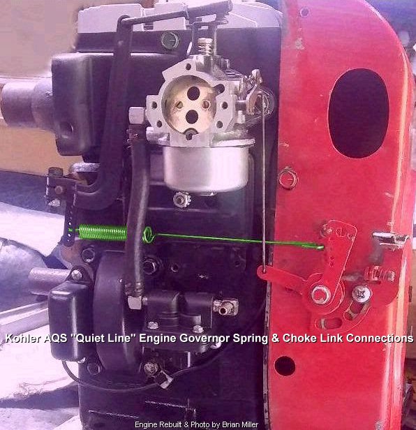
 Placing the end of the governor
spring in one of the uppermost holes of the reversed L-shaped governor lever
on a Kohler engine model K241, K301, K321, K341 and K361, or Magnum engine
model M10, M12, M14, M16 decreases the RPM speed of the engine, and placing
the spring in one of the lowermost holes of the reversed L-shaped governor
lever increases the RPM speed of the engine. The opposite is true with the
spring in the holes of the speed control bracket on ordinary Kohler K241-K361
engines (with the short 26 coil governor spring), Kohler AQS "Quiet Line"
(K241-K361 models with the 34 coil Extended-Length governor spring) and Kohler
Magnum M10-M16 engines (with the 26 coil or 34 coil governor spring). These
engines have a top speed of 3,600 RPM (with a fully adjustable high speed
jet carburetor) or 3,200 RPM (with a non-adjustable/fixed high speed jet
carburetor) with the ends of the governor spring in one of the middle holes
of either lever. (Read more below.) Use medium size
needle-nose pliers to unhook and reinsert the end(s) of
the spring in either lever. Be careful not to distort the ends or overstretch
the spring! Or the speed control bracket may need to be unfastened from the
block to position or reposition the spring in the holes in either lever.
Placing the end of the governor
spring in one of the uppermost holes of the reversed L-shaped governor lever
on a Kohler engine model K241, K301, K321, K341 and K361, or Magnum engine
model M10, M12, M14, M16 decreases the RPM speed of the engine, and placing
the spring in one of the lowermost holes of the reversed L-shaped governor
lever increases the RPM speed of the engine. The opposite is true with the
spring in the holes of the speed control bracket on ordinary Kohler K241-K361
engines (with the short 26 coil governor spring), Kohler AQS "Quiet Line"
(K241-K361 models with the 34 coil Extended-Length governor spring) and Kohler
Magnum M10-M16 engines (with the 26 coil or 34 coil governor spring). These
engines have a top speed of 3,600 RPM (with a fully adjustable high speed
jet carburetor) or 3,200 RPM (with a non-adjustable/fixed high speed jet
carburetor) with the ends of the governor spring in one of the middle holes
of either lever. (Read more below.) Use medium size
needle-nose pliers to unhook and reinsert the end(s) of
the spring in either lever. Be careful not to distort the ends or overstretch
the spring! Or the speed control bracket may need to be unfastened from the
block to position or reposition the spring in the holes in either lever.
It's best
to set the engine maximum RPM with an accurate
tachometer to determine the exact speed of the
crankshaft to prevent the engine from dangerously over-revving, which could
possibly cause the connecting rod to burn or possibly break, which could
destroy the engine block. The maximum RPM for virtually any stock lawn &
garden small engine with a fully adjustable high speed main jet carburetor
is 3,600; and the maximum RPM for a stock lawn & garden small engine
with a fixed/non-adjustable high speed main jet carburetor is 3,200. Moreover,
for [Kohler] engines with camshaft-operated ignition points, with certain
type of tachometers, the RPM reading/display will
need to be doubled. But with crankshaft-operated points or with
flywheel-triggered solid state ignition, or with crank trigger ignition,
the reading will not need to be doubled.
| Advertisement for Tachometers and Tachometer Kits - Click here to contact A-1 Miller's Performance Enterprises to place an order, send your parts for repairing, and/or for FREE professional and honest technical customer service assistance and support and payment options. If you need a part or parts that's not listed in this website, please contact A-1 Miller's and we'll see if we can get it at a reasonable price. [Top of Page] Nowadays, prices are subject to change without notice. |
 High Quality Inductive
Small Engine Tachometer/Hour Meter with Replaceable Battery. A tachometer
is required for monitoring and/or setting the maximum speed of a small engine,
which is normally 3,200 or 3,600 RPM (depending on type of carburetor), to
prevent from over-revving and possible damage to the engine or dangerous
flywheel explosion. Very accurate, vibration-proof and weatherproof construction.
Can be surface-mounted and secured with two screws to monitor engine RPM,
or hand-held to set engine RPM. Large 3/8 inch LCD display. Works with magneto
or battery-powered ignition systems by selecting engine type by programming
S1 and S2 buttons. If tachometer does not turn on automatically as soon
as engine starts, press and hold the two buttons at the same time.
Instructions included. Reads up to 99,999 RPM. Hour meter reads up to 9999:59
hours/minutes. Programmable maintenance hour setting with service icon, a
service reminder when to change oil or other maintenance. Can be manually
reset to Zero hours. Easy installation: Single wire wraps around spark plug
wire and secured with two supplied nylon zip-ties. No wire terminal connections
required. Includes replaceable CR2450 battery. Dimensions: 2" wide x 1-3/4"
depth x 3/4" height. $25.00 each, plus shipping & handling. Please
let me know if you're interested in purchasing this
item and I'll give you the total amount with shipping and payment options. High Quality Inductive
Small Engine Tachometer/Hour Meter with Replaceable Battery. A tachometer
is required for monitoring and/or setting the maximum speed of a small engine,
which is normally 3,200 or 3,600 RPM (depending on type of carburetor), to
prevent from over-revving and possible damage to the engine or dangerous
flywheel explosion. Very accurate, vibration-proof and weatherproof construction.
Can be surface-mounted and secured with two screws to monitor engine RPM,
or hand-held to set engine RPM. Large 3/8 inch LCD display. Works with magneto
or battery-powered ignition systems by selecting engine type by programming
S1 and S2 buttons. If tachometer does not turn on automatically as soon
as engine starts, press and hold the two buttons at the same time.
Instructions included. Reads up to 99,999 RPM. Hour meter reads up to 9999:59
hours/minutes. Programmable maintenance hour setting with service icon, a
service reminder when to change oil or other maintenance. Can be manually
reset to Zero hours. Easy installation: Single wire wraps around spark plug
wire and secured with two supplied nylon zip-ties. No wire terminal connections
required. Includes replaceable CR2450 battery. Dimensions: 2" wide x 1-3/4"
depth x 3/4" height. $25.00 each, plus shipping & handling. Please
let me know if you're interested in purchasing this
item and I'll give you the total amount with shipping and payment options.
|
Advertisement for Governor Parts - Click here to contact A-1 Miller's Performance Enterprises to place an order, send your parts for repairing, and/or for FREE professional and honest technical customer service assistance and support and payment options. If you need a part or parts that's not listed in this website, please contact A-1 Miller's and we'll see if we can get it at a reasonable price. | [Top of Page] Nowadays, prices are subject to change without notice.
  Kohler Governor Cross Shaft Bushings with Rubber O-Ring
to Prevent Oil Leak. Rubber O-ring fits snug in bushing and on cross
shaft, and has no effect with movement of governor leverage whatsoever. WHY
HAVING THIS O-RING INSTALLED IS IMPORTANT: On single cylinder Kohler engines,
vacuum within the crankcase created by the upward stroke of the piston draws
in a small amount of outside air, along with a small amount of dust, dirt
and debris through the governor bushing and shaft, pressurized air within
the crankcase created by the downward stroke of the piston blows out a fine
mist of crankcase oil through the bushing and shaft. Overtime, the dust,
dirt and debris of this repeated pulsating action will, without a doubt,
cause the bushing (and sometimes the shaft, too) to wear, which cause a thin
film of oily mess to exist on the outside of the engine block. IMPORTANT
INFORMATION UPON REMOVAL OF THE BUSHING: When removing the old bushing, use
caution to prevent the governor cross shaft from pulling outward and possibly
falling down inside the crankcase! If this happens, the entire engine
must be completely disassembled just to reinstall the governor cross shaft
in place. Also, before installing this bushing with the O-ring, apply clean
oil inside the bushing and O-ring and/or on the shaft for lubrication. With
no prior lubrication, the dry bushing and rubber will eventually wear dry
from friction, possibly causing a new oil leak. Do the job right the first
time, and it won't have to be done again for a long time. Kohler Governor Cross Shaft Bushings with Rubber O-Ring
to Prevent Oil Leak. Rubber O-ring fits snug in bushing and on cross
shaft, and has no effect with movement of governor leverage whatsoever. WHY
HAVING THIS O-RING INSTALLED IS IMPORTANT: On single cylinder Kohler engines,
vacuum within the crankcase created by the upward stroke of the piston draws
in a small amount of outside air, along with a small amount of dust, dirt
and debris through the governor bushing and shaft, pressurized air within
the crankcase created by the downward stroke of the piston blows out a fine
mist of crankcase oil through the bushing and shaft. Overtime, the dust,
dirt and debris of this repeated pulsating action will, without a doubt,
cause the bushing (and sometimes the shaft, too) to wear, which cause a thin
film of oily mess to exist on the outside of the engine block. IMPORTANT
INFORMATION UPON REMOVAL OF THE BUSHING: When removing the old bushing, use
caution to prevent the governor cross shaft from pulling outward and possibly
falling down inside the crankcase! If this happens, the entire engine
must be completely disassembled just to reinstall the governor cross shaft
in place. Also, before installing this bushing with the O-ring, apply clean
oil inside the bushing and O-ring and/or on the shaft for lubrication. With
no prior lubrication, the dry bushing and rubber will eventually wear dry
from friction, possibly causing a new oil leak. Do the job right the first
time, and it won't have to be done again for a long time.
  Governor Cross Shaft Bushings with 7/32" hole x 1/2-13 UNC
threads. Each fits various Kohler engine models K90/K91, K141, K160/K161,
L160/L161, L181, K181
and various early M8 engines with
V-shaped/coiled governor spring.
NOTE: When ordering, please specify engine model, specification and
serial numbers, or identification of your bushing. Governor Cross Shaft Bushings with 7/32" hole x 1/2-13 UNC
threads. Each fits various Kohler engine models K90/K91, K141, K160/K161,
L160/L161, L181, K181
and various early M8 engines with
V-shaped/coiled governor spring.
NOTE: When ordering, please specify engine model, specification and
serial numbers, or identification of your bushing.
 Governor Cross Shaft Bushing
with 7/32" hole x 1/2-13 UNC threads. Fits Kohler engine model K181
w/specification # 301000-301045, and various later M8 engines with
coiled extension governor spring.
NOTE: When ordering, please specify engine model and specification
numbers. Governor Cross Shaft Bushing
with 7/32" hole x 1/2-13 UNC threads. Fits Kohler engine model K181
w/specification # 301000-301045, and various later M8 engines with
coiled extension governor spring.
NOTE: When ordering, please specify engine model and specification
numbers.
 Governor Cross Shaft Bushing
with 1/4" hole x 1/2-13 UNC threads. Fits all Kohler K-series and Magnum
engine models K241, M10, K301, M12, K321, M14, K341, M16 and K361. Governor Cross Shaft Bushing
with 1/4" hole x 1/2-13 UNC threads. Fits all Kohler K-series and Magnum
engine models K241, M10, K301, M12, K321, M14, K341, M16 and K361.
   Alignment Washers and Spacer. Fits
Governor Cross Shaft listed above. Fits most Kohler engine models K141,
K160/K161, KV161,
L160/L161, L181, K181 and
M8. Goes on governor cross shaft listed above, and locates between governor
cross shaft bushing (listed above) and step on cross shaft to maintain proper
alignment of lever on shaft with center button on governor gear assembly. Alignment Washers and Spacer. Fits
Governor Cross Shaft listed above. Fits most Kohler engine models K141,
K160/K161, KV161,
L160/L161, L181, K181 and
M8. Goes on governor cross shaft listed above, and locates between governor
cross shaft bushing (listed above) and step on cross shaft to maintain proper
alignment of lever on shaft with center button on governor gear assembly.
 Alignment Spacers. Fits
Governor Cross Shaft listed above. Fits all Kohler engine models K241, M10,
K301, M12, K321, M14, K341, M16 and K361. Goes on governor cross shaft listed
above, and locates between governor cross shaft bushing (listed above) and
lever to maintain proper alignment of lever with center button on governor
gear assembly. Alignment Spacers. Fits
Governor Cross Shaft listed above. Fits all Kohler engine models K241, M10,
K301, M12, K321, M14, K341, M16 and K361. Goes on governor cross shaft listed
above, and locates between governor cross shaft bushing (listed above) and
lever to maintain proper alignment of lever with center button on governor
gear assembly.
 Governor Cross Shaft End
Bearing (Tiny Steel Bushing
w/Blind Hole). Fits various Kohler engine models K181,
L160/L161, L181, M8, K241, M10, K301, M12, K321,
M14, K341 and M16 with machined through-hole in block for end of governor
cross shaft. OEM Kohler part # 234866-S. Governor Cross Shaft End
Bearing (Tiny Steel Bushing
w/Blind Hole). Fits various Kohler engine models K181,
L160/L161, L181, M8, K241, M10, K301, M12, K321,
M14, K341 and M16 with machined through-hole in block for end of governor
cross shaft. OEM Kohler part # 234866-S.
Nylon Governor Gear Assembly
with
Asymmetrical (Offset) Flyweights. Designed specifically
for Kohler engine models K241, M10, K301, M12, K321, M14, K341 and M16 used
with an air compressor, generator and/or welding unit. Also ideal for
use in a 4,000± RPM competition pulling engine. Recovers engine RPM
quickly when under a load and maintains engine RPM at a more steady pace.
IMPORTANT: Apply oil or grease on stub shaft to prevent wear or damage
to governor gear assembly upon engine startup until crankcase oil reach this
area.
Cast Iron Governor Gear Assembly
with
Symmetrical Flyweights. Fits Kohler engine models K141,
K160/K161, K181, L160/L161, L181, M8, K241,
M10, K301, M12, K321, M14, K341, M16, KT17 (first design), KT17 Series II,
KT19/KT19 Series II, KT21, MV16, M18, MV18, M20 and MV20. Recommended for
high RPM or
wide
open throttle competition pulling engines. Will not become distorted
or explode at high RPM or at open RPM like the nylon governor gears sometimes
do. (Kohler never made a steel governor gear.) IMPORTANT: Apply oil or
grease on stub shaft to prevent wear or damage to governor gear assembly
upon engine startup until crankcase oil reach this area.
Thrust Washers for Governor Gear Assemblies. Fits Kohler engine models K241, M10, K301, M12, K321, M14, K341, M16, K361, KT17, KT17 Series II, KT19, KT19 Series II, KT21, MV16, M18, MV18, M20 and MV20. A thrust washer is required to prevent the governor gear from wearing against the engine block when the governor gear is under full pressure from the engine running at higher RPM. Many people are not aware of the thrust washer because it may appear to be part of the engine block, and it usually falls out and gets lost while cleaning inside the block. IMPORTANT: Apply oil or grease on stub shaft to prevent wear or damage to governor gear assembly upon engine startup until crankcase oil reach this area.
Governor Gear Stub Shafts. NOTE: Install each stub shaft listed below until .345" (11/32") protrudes from the block, and apply oil or grease on it to prevent wear to governor gear assembly to prevent a dry engine startup until crankcase oil reach this area. FYI - All OEM Kohler stub shafts that originally come in the engine are smooth the entire length. Only new OEM replacement stub shafts are knurled on one end. Therefore, perhaps the OEM stub shaft can be reused by reinstalling it in reverse if the worn half fits tight in the block. Click here to learn how to replace the worn governor gear stub shaft and reinstall the same welch/expansion plug. [Return to previous section]
|
Advertisement for Throttle Bracket, Throttle and Choke Cable Assemblies, and High Quality Universal Foot/Gas Pedal Kit - Click here to contact A-1 Miller's Performance Enterprises to place an order, send your parts for repairing, and/or for FREE professional and honest technical customer service assistance and support and payment options. If you need a part or parts that's not listed in this website, please contact A-1 Miller's and we'll see if we can get it at a reasonable price. | [Top of Page] Nowadays, prices are subject to change without notice.
 Universal-Fit Replacement
Choke or Throttle Control T-Handle. Replace damaged or missing OEM ball-shaped
knob or T-handle for more comfortable operation of in-dash or panel-mounted
choke or throttle cable control lever. Made of tough, durable plastic. Push-on
or use small hammer to install. $1.50 each, plus shipping & handling. Universal-Fit Replacement
Choke or Throttle Control T-Handle. Replace damaged or missing OEM ball-shaped
knob or T-handle for more comfortable operation of in-dash or panel-mounted
choke or throttle cable control lever. Made of tough, durable plastic. Push-on
or use small hammer to install. $1.50 each, plus shipping & handling. |
  Lever-Action Solid Wire Remote Throttle Control Cable Assemblies.
Side mount. Fits Cub Cadet garden tractor models 70, 71, 72, 73, 100, 102,
104, 122, 123, 124, 125, 126, 127 and 147. Lever-Action Solid Wire Remote Throttle Control Cable Assemblies.
Side mount. Fits Cub Cadet garden tractor models 70, 71, 72, 73, 100, 102,
104, 122, 123, 124, 125, 126, 127 and 147.
|
 Push/Pull Solid Wire Remote
Choke Control Cable Assemblies for all narrow frame Cub Cadet garden tractors. Push/Pull Solid Wire Remote
Choke Control Cable Assemblies for all narrow frame Cub Cadet garden tractors.
Choke Cable Control Assembly. Fits Cub Cadet garden tractor models 580, 582, 1604 and 1606. Cub Cadet part # 746-3004. Discontinued from Cub Cadet and not available in aftermarket. |
 Throttle Wire/Cable Swivel
Kits. Use to secure stranded cable or solid wire to speed regulating disc
or speed control bracket/lever (each listed below) for go-karts, small motorized
vehicles, stock/governed Kohler competition pulling engines or secure to
throttle lever on Carter/Kohler carburetor for an open RPM Kohler competition
pulling engine. Each kit requires a 15/64" / .230" / 6mm hole, and includes
wire swivel, screw and friction washer. Throttle Wire/Cable Swivel
Kits. Use to secure stranded cable or solid wire to speed regulating disc
or speed control bracket/lever (each listed below) for go-karts, small motorized
vehicles, stock/governed Kohler competition pulling engines or secure to
throttle lever on Carter/Kohler carburetor for an open RPM Kohler competition
pulling engine. Each kit requires a 15/64" / .230" / 6mm hole, and includes
wire swivel, screw and friction washer.
|
 Speed Control Bracket/Lever
with 15/64" / 6mm hole for throttle swivel assembly (listed above). Commonly
used on most Kohler engine models K241, K301, K321 and K341 with the
round shaped metal air cleaner/filter
assembly. Not for use on AQS "Quiet Line" engines. New Old Stock or used
and in excellent condition. Discontinued Kohler part # 235086-S. $4.75
each, plus shipping & handling. Speed Control Bracket/Lever
with 15/64" / 6mm hole for throttle swivel assembly (listed above). Commonly
used on most Kohler engine models K241, K301, K321 and K341 with the
round shaped metal air cleaner/filter
assembly. Not for use on AQS "Quiet Line" engines. New Old Stock or used
and in excellent condition. Discontinued Kohler part # 235086-S. $4.75
each, plus shipping & handling.
Speed Control Bracket/Lever with yoke, for use with a grooved end adjustment screw (discontinued Kohler part # 237574-S) on various Kohler 10-16hp engines. Sets engine RPM at desired/fixed position. Commonly used on generators/welders, water pumps, etc. OEM Kohler part # 236413-S. $10.70 each, plus shipping & handling. NOTE - We have the capability to fabricate and duplicate obsolete and hard to find throttle linkages and levers. If interested, please email me a photo of the part(s) that's needed (if possible) with the exact dimensions. |
Use a Foolproof Type of Foot-Operated, Spring-Loaded, Throttle Return Control Setup on a Competition Garden Pulling Tractor - [Top of Page]


 For a distinctive
and noticeable appearance, install a chrome-plated, die-cast aluminum
barefoot gas pedal on a competition garden pulling tractor.
This nostalgic item was popular in the late '60s to early '70s and was used
mainly on street rods and hot rod vehicles of the time. This barefoot pedal
can be easily clamped or fastened to the universal pedal listed above, or
a medium size household brass (to prevent rust) door hinge can be used to
fasten this pedal to the foot rest/support/running board of the tractor.
For a distinctive
and noticeable appearance, install a chrome-plated, die-cast aluminum
barefoot gas pedal on a competition garden pulling tractor.
This nostalgic item was popular in the late '60s to early '70s and was used
mainly on street rods and hot rod vehicles of the time. This barefoot pedal
can be easily clamped or fastened to the universal pedal listed above, or
a medium size household brass (to prevent rust) door hinge can be used to
fasten this pedal to the foot rest/support/running board of the tractor.
When using a Carter or Kohler carburetor, a spring-loaded throttle control is a safety feature because the engine will idle down as soon as the driver lets off the gas pedal, just like in an automobile. But with the OEM-type, manually-operated solid wire throttle control, the driver must quickly reach for the throttle lever to idle down the engine. Many pulling association/club sanctioning general rules and requirements state that a spring-loaded throttle control must be used for safety, either hand- or foot-operated (hand lever or foot pedal). All Mikuni carburetors have a built-in spring-loaded throttle return.
(Updated 9/9/25) Stranded Wire Cable Spring-Return Throttle Control Setup for 10-16hp 4,000± RPM Governed Kohler Competition Pulling Engines - [Return to previous website or section]

 First of all,
virtually all sliding stranded wire cable/housing assemblies are shipped
dry from the factory with no lubrication. Therefore, when using a sliding
stranded wire cable/housing control to operate the throttle smoothly, in
order for the inner cable to slide back and forth with ease and less friction
inside the housing, remove or pull out the inner cable from the housing (with
one [ball] end cut off), and pump motor oil, or better yet, use a
First of all,
virtually all sliding stranded wire cable/housing assemblies are shipped
dry from the factory with no lubrication. Therefore, when using a sliding
stranded wire cable/housing control to operate the throttle smoothly, in
order for the inner cable to slide back and forth with ease and less friction
inside the housing, remove or pull out the inner cable from the housing (with
one [ball] end cut off), and pump motor oil, or better yet, use a
 needle grease injector (resembles a
hypodermic syringe) that attach to an
automotive grease gun or a
[Dualco] chainsaw roller/sprocket tip grease gun to pump
a small amount of grease inside the housing so the cable will slide smoother
and easier with less friction. But before reinserting the cable in the housing,
and to prevent the end of it from unraveling, which will make it very difficult
to reinsert the cable into the housing,
fuse together the end of the stranded wire with a
propane or
oxy-acetylene torch (with a small, blue flame) to melt
the strand of wires together and then carefully grind down the lump of molten
metal to a point so the permanently joined strand of wires can be easily
reinserted into the housing and through the wire swivel clamp with no difficulty.
By the way - the needle grease injector or chainsaw bar tip grease gun
can also be used to relubricate used sealed ball bearings or add extra grease
to new sealed ball bearings so it will last longer. And the chainsaw bar
tip grease gun is handy for lubricating a lot of small things.
needle grease injector (resembles a
hypodermic syringe) that attach to an
automotive grease gun or a
[Dualco] chainsaw roller/sprocket tip grease gun to pump
a small amount of grease inside the housing so the cable will slide smoother
and easier with less friction. But before reinserting the cable in the housing,
and to prevent the end of it from unraveling, which will make it very difficult
to reinsert the cable into the housing,
fuse together the end of the stranded wire with a
propane or
oxy-acetylene torch (with a small, blue flame) to melt
the strand of wires together and then carefully grind down the lump of molten
metal to a point so the permanently joined strand of wires can be easily
reinserted into the housing and through the wire swivel clamp with no difficulty.
By the way - the needle grease injector or chainsaw bar tip grease gun
can also be used to relubricate used sealed ball bearings or add extra grease
to new sealed ball bearings so it will last longer. And the chainsaw bar
tip grease gun is handy for lubricating a lot of small things.
To fabricate a stranded wire cable spring-return throttle control setup for a 4,000± RPM governed Kohler K-series 10-16hp competition pulling engine or small all-terrain vehicle engine with a Kohler K-series 10-16hp engine...
 Replace the upper left cam gear
cover bolt with an extended 1-1/2" length bolt and jam nut. Tighten the jam
nut against the cam cover (to prevent an oil leak).
Replace the upper left cam gear
cover bolt with an extended 1-1/2" length bolt and jam nut. Tighten the jam
nut against the cam cover (to prevent an oil leak).
If correctly installed and adjusted, this type of throttle control should work flawlessly and last a long time with very little wear to the stranded wire cable.
Oh, and if you've ever wondered what a "dead man's throttle" is, it's a spring-loaded foot pedal or hand throttle lever control that automatically returns the throttle plate to the idle position when the pressure is released. It works the same as the gas pedal in a car.

How to Limit the RPM and Safely Operate Virtually Any 4-Stroke Small Engine Without a Working Governor [Top of Page]
 Certain Kohler engines came
from the factory without a governor assembly and with no provisions in or
on the block to install governor components. These particular engines were
made for a specific use or for a lightweight vehicle, such as for a go-kart,
King Midget micro car, older snowmobile, etc. Being there's
no governor components in these engines (listed below) that automatically
opens the throttle when the engine is under a load, these are capable of
running at wide open throttle, and can't be used for general lawn and garden
usage, so caution must be taken not to over-rev the engine for a prolong
time to prevent connecting rod burning or breakage, or possible flywheel
explosion.
Certain Kohler engines came
from the factory without a governor assembly and with no provisions in or
on the block to install governor components. These particular engines were
made for a specific use or for a lightweight vehicle, such as for a go-kart,
King Midget micro car, older snowmobile, etc. Being there's
no governor components in these engines (listed below) that automatically
opens the throttle when the engine is under a load, these are capable of
running at wide open throttle, and can't be used for general lawn and garden
usage, so caution must be taken not to over-rev the engine for a prolong
time to prevent connecting rod burning or breakage, or possible flywheel
explosion.
Kohler engine models K141, K161, K181, K241 and K301 that originally came with no factory-installed governor components have the following specification numbers: K141-29169, 29172, 29186, 29189, 29190, 29191, 29238, 29252, 29275, 29333; K161-2889, 28143, 28425, 28560, 28575, 28663, 28729, 28763, 28797, 28838, 28934, 28947; K161-2889, 28143, 28425, 28560, 28575, 28663, 28729, 28763, 28797, 28838, 28934, 28947; K181-30102, 30123, 30124, 30129, 30130, 30138, 30142, 30151, 30165, 30166, 30167, 30169, 30181, 30185, 30216, 30224, 30225, 30228, 30235, 30240, 30242, 30259, 30262, 30268, 30269, 30288, 30306, 30307, 30308, 30310, 30317, 30325, 30384; K241-46202, 46254, 46393 and 46447; K301-4743, 4751, 47103, 47119, 47127. All other Kohler engine models/specs not listed have governor components installed by the factory.
Here's how to limit the RPM for a virtually any engine without a governor: the camshaft is simply advanced by one tooth in relationship to the crankshaft. (The engines mentioned above DO NOT have the cam advanced.) With the cam advanced by one tooth, at full throttle and when the engine is under a load, it will NOT rev at wide open throttle and throw the rod. The engine will still produce plenty of power to get the job done. Advancing the cam opens the valves sooner than normal. In return, this allows the engine to run at a much lower compression. At full throttle, a low compression engine will NOT rev as high as a high compression engine. (The Ford Model T engine, that have a 4:1 compression ratio, will only rev to around 1,750 RPM at full throttle.) The lower compression does not shorten the life of the engine. In fact, it helps to extend engine life because under low compression, the combustion chamber heat operates at a lower temperature, allowing the engine to naturally run cooler, which helps it last longer. NOTE: The camshaft in the Kohler K-series engines cannot be advanced at all because the ignition points operate off the cam, which sets the correct ignition timing. The cam can be advanced with a Kohler Magnum (with solid state ignition) or if the Kohler K-series engine have crank-trigger or flywheel-trigger electronic ignition.
With the cam advanced by one tooth, if the engine is in good condition, it should start quickly, idle smoothly and produce plenty of power up to around 3,400± RPM at full throttle when under a load. But when using camshaft-operated ignition points and with the cam advanced one tooth, this would also advance the ignition timing way too far. Regarding the Kohler K-series engines, being the ignition points operate off the cam and being the camshaft is advanced by one tooth, the ignition timing will be far too advanced for the engine to start easily and run correctly. Therefore, for the timing to be set at 20º BTDC, the engine will need to have either Breakerless Ignition, magneto to solid state ignition conversion, Kohler Magnum solid state ignition, or a custom flywheel-trigger electronic ignition system, which are all triggered by the flywheel, or custom crank-trigger electronic ignition system, which is triggered off the crankshaft.
As a matter of fact, the camshaft was advanced by one tooth on Tecumseh Engines with certain older (mid 1970's era) Sears Craftsman Eager 1 walk-behind or self-propelled lawn mower engines that have no governor components installed by Tecumseh. The remote solid wire cable connect directly to the carburetor throttle lever to vary the engine speed (up to around 3,400± RPM at full throttle). Certain models (4hp/LAV40?) of mid-1970's Sears Craftsman Eager 1 walk-behind or self-propelled lawn mower engines with no governor components have either a very low compression cylinder head with an extremely huge combustion chamber to lower the compression ratio significantly, which limit the engine speed up to around 3,400± RPM; and other models of mid-1970's Sears Craftsman Eager 1 engines with no governor components have a cylinder head with an ordinary size combustion chamber and a carburetor that have an extremely small diameter throttle bore and an extremely small inside diameter intake extension tube that reduce the velocity of air/fuel the engine can draw in, which lowers the compression and limit the engine speed up to around 3,400± RPM). (Incidentally, this works exactly the same as the restrictor plate used in certain sanctioned racing go-kart and NASCAR classes.) And certain other models of mid-1970's Sears Craftsman Eager 1 engines with no governor components have a cylinder head with an ordinary size combustion chamber with a carburetor/intake extension tube of ordinary size, but the camshaft is advanced by one tooth in relationship to the crankshaft, which lowers the compression and limit the RPM up to around 3,400±. These are all proven designs to limit the engine RPM and works very well. These engines still produced plenty of power to get the job done. (We know this for a fact, because after the tune-up or repairs and blade sharpening, we tested each one in tall field grass and they did not lug down whatsoever.) Personally, back in the day (early 1980's), we've had all of these Sears Craftsman Eager 1 engines in our shop brought to us by customers for a tune-up and/or repairs. These are apparently very rare engines. If they were not in our shop at the time, we would not have known that they existed. And we don't know why new small engines like these are not available today. Every small engine manufactured nowadays have a working mechanical governor.
 Another way to limit the RPM
of an engine without a working governor and the camshaft aligned with
the crankshaft is to install multiple cylinder head gaskets or a thick
metal plate sandwiched between two head gaskets to lower the compression
pressure in the combustion chamber dramatically. This too, will prevent the
engine from accelerating to its full potential at wide open throttle. The
number of head gaskets or thickness of the plate determines to maximum RPM
of the engine.
Another way to limit the RPM
of an engine without a working governor and the camshaft aligned with
the crankshaft is to install multiple cylinder head gaskets or a thick
metal plate sandwiched between two head gaskets to lower the compression
pressure in the combustion chamber dramatically. This too, will prevent the
engine from accelerating to its full potential at wide open throttle. The
number of head gaskets or thickness of the plate determines to maximum RPM
of the engine.
And yet another way to limit the RPM of an engine without a working governor, with the camshaft aligned with the crankshaft, and with a normal compression ratio is to install a restrictor plate with a specific hole size between the carburetor and intake tube or engine block.
The three methods above can be useful with an engine in go-karts, King Midget micro cars, older snowmobiles, older small all terrain vehicles, etc. And being there's no governor whatsoever, it cannot be altered or readjusted to allow the engine to accelerate at dangerously higher RPM. The engine speed will be limited by the low compression ratio or restricted airflow intake only.
Pulling at Open RPM With No Operating Governor - (added 5/23/15
On a pulling engine that pulls at open RPM, and the governor will never be used, remove all the governor parts inside the crankcase and outside the engine, and plug the hole in the block where the brass governor bushing goes with a 1/2" UNC (coarse thread) Allen set screw. Clean the threads and use liquid threadlocker (Red Loctite or Permatex) to secure the screw in place. FYI - When storing an opened container of liquid threadlock material or Super Glue, store it upright and not laying flat. The [capped] tip will not dry out and clog when stored upright. By getting rid of all the governor parts, this makes for a "clean-looking" and professionally-built pulling engine.
 Upon installation of a connecting rod in a Kohler
engine, make sure the match marks on the rod and cap are aligned so the hole
will make a perfect circle around the crank journal. If they're not aligned,
the circle will be offset, resulting in crankshaft binding and possible rod/cap
distortion when the bolts or nuts are torqued to specs. Also, make sure the
oil hole in the rod cap faces the camshaft so the hole will pick up the oil
and lubricate the rod better.
Upon installation of a connecting rod in a Kohler
engine, make sure the match marks on the rod and cap are aligned so the hole
will make a perfect circle around the crank journal. If they're not aligned,
the circle will be offset, resulting in crankshaft binding and possible rod/cap
distortion when the bolts or nuts are torqued to specs. Also, make sure the
oil hole in the rod cap faces the camshaft so the hole will pick up the oil
and lubricate the rod better.
Connecting rods, rather being OEM or aftermarket (stock or high performance), and despite how well-balanced the rotating parts are in a pulling engine, suffer a lot of stress at open RPM in a single cylinder engine. Therefore, if possible, before purchasing a used rod, it's best to look it over for hairline cracks with a strong magnifying glass or better yet, a microscope. And as I always say about buying anything off of eBay: BUYER BEWARE! So ask for a money-back guarantee, or you may have nothing but a piece of scrap metal on your hands.
If using a stock connecting rod above 4,000± RPM, an aluminum bearing surface rod should never be used. Because the extreme pressure and heat from the rapid rotation of the rod on the crankshaft journal cause the aluminum to swell and this could cause the oil clearance to lessen making the aluminum have contact with the crankshaft, minimizing the oil clearance, which will overheat and become scored, resulting in crankshaft journal/rod scoring or burning, engine seizure or even rod breakage. One way around this, if replaceable bearing inserts isn't available for your particular rod, is to have the rod surface enlarged an additional one thousands of an inch (.001") to allow for additional oil clearance (the extra .001" of clearance will not cause the rod to knock) and to make room for the aluminum to swell when it gets hot. Or if your rod can accept bearing inserts (10hp-16hp Kohler rods), have automotive-type bearing inserts installed, even if the rod is new or used, or if it has a relatively good bearing surface. The reason bearing inserts work best in high performance or heavy duty conditions is because the soft babbitt material (lead) that's on the inserts can withstand extreme heat and extreme pressure. It also "cushions" the extreme pressure that the rod places on the crankshaft journal at open RPM. And it's still a good idea to have an additional .001" of additional oil clearance, even if bearing inserts are used. Using bearing inserts also strengthens a [stock] rod by cushioning the severe impact the rod places on the crankshaft at very high RPM.
If a plain aluminum bearing surface connecting rod is scored or burnt on the crankshaft, the causes are either...
|
|
No connecting rod in any 10hp-16hp K-series Kohler engine come from the factory with bearing inserts in them. The rod must be machined (bored and notched) for installation of bearing inserts. Kohler don't make bearing inserts for the connecting rod in any of their single cylinder engines. But the bearings fit the Kohler rod perfectly after it's been bored out. The bearings are available in STD, .010", .020" and .030" undersizes. Also, these bearings can only be used in Kohler engines with a 1.500" diameter crankshaft journal/crank pin (or undersizes), such as the 10hp through 18hp single cylinder engines and all of their opposed twin cylinder engines with a stock (OEM) or an aftermarket connecting rod. No bearing inserts that I know of is designed for use in any other Kohler engines, except for the Kohler engine models K482, K582 and K682 if the crank journals were reground to 1.500". (STD size is 1.625".) The connecting rods would not need to be bored, being they are already 1.625" in diameter. But they would need to be notched for the tangs on the bearing inserts.
Or, being the K241 and K482 engines share the same pistons and have the same stroke, and their connecting rods are the same length, a K241 connecting rod can be used in a K482 engine when bored and honed to 1.625"-1.626" to match the STD size K532 or K582 crank journal, which are 1.624" (allow .001"-.002" for oil clearance). If the K482 journals are worn and reground undersize, the K241 rod can be bored and honed to fit the undersize journals. The oil dipper on these rods will need to be cut off as well. Boring these single cylinder engine rods will not weaken them whatsoever because they hold up very well when bored and used with bearing inserts in the respective single cylinder engines.
To install bearing inserts in virtually any connecting rod, accurately measure the STD size diameter of the crank journal, add the thickness of each bearing insert shell, and this will give the exact diameter of the hole in the rod that needs to be bored. But not all connecting rods will accept bearing inserts, and bearing inserts are not available for certain rods.
About Machining a Connecting Rod for Installation of Replaceable Bearing Inserts - Before I machine a rod for bearing inserts, I use a metal "plug" alignment tool that I made in my metal lathe to precisely align the big hole of the connecting rod with the centerline of the spindle in my milling machine. Then while the plug is in the rod, I firmly clamp the rod to the table of my milling machine and after leaving the big hole centered or moving the table offset for piston pop-out, I securely lock the table so the rod won't move in any direction. But for reasons unknown, sometimes the cutter/reamer will bore the hole in the rod slightly off-center and make contact with one of the bolts or sleeves (for studs) in the rod. Whenever this happens, I simply grind away (notch out) part of each bearing shell so they'll clear the rod bolt or sleeve. I've talked to other experienced machinist who bore Kohler rods about this and they told A-1 Miller's sometimes the same thing happens with them. But as long as the bearing shells are ground for clearance of the bolt/sleeve, this poses no problems.
For high RPM use, bearing inserts also need additional oil clearance. Therefore, it's good insurance to have the crank journal ground an additional .001" for extra oil clearance. As the rod and journal swell due to the rapid rotation of the two parts, metal to metal contact won't happen. Of course, it's a good idea to use full synthetic oil, too. And once a journal's been reground to exactly .010", it's awful hard to ground an additional .001" on it, making it .011" undersize. If the journal has been ground to exactly .010", the rod would need to be honed an extra .001" instead.
Sometimes an OEM connecting rod will need to be bored for installation of bearing inserts when the crank journal must be reground deeper than .010" undersize. (STD size and .010" undersize OEM connecting rods are the only two sizes that's available from Kohler.) But bearings are available in STD, .010", .020" and .030" undersizes, to match the reground journal. If your crank journal needs to be reground to .020" or .030" undersize, then undersized bearing inserts will need to be installed in the rod to match the diameter of the crank journal. Bearings can only be installed in the 10-16hp single cylinder flathead Kohler engines, the 18hp OHV single cylinder Kohler engine, the KT21 and M20 opposed twin cylinder Kohler engine, because these engines all have a 1-1/2 diameter crank journal. Bearing inserts also help to provide longevity of the journal, just like in automotive engines.
More Information About Replaceable Bearing Inserts (Rod Bearings) -
For pulling applications, the oil clearance between the rod bearing and crank journal should be .0015"-.0025" with ± .0005" for wear. The .0025" allows .001" more clearance for rod swelling (when hot; only at open RPM). It'll be good to use this clearance for stock engines, too.
Bearing inserts provide a little more oil clearance to protect the crank journal. If checking the oil clearance with PlastiGage, and if it shows the clearance to be .0015"-.0025", don't worry about it. It'll work just fine. Many race cars run this much clearance. The rod won't knock either.
Boring a Kohler rod and installing bearing inserts in it doesn't weaken the rod whatsoever. Because whenever a rod breaks, 99% of the time they break in the beam section, not around the bearing area. And bearing inserts add very little weight. Meaning they don't upset the balance of the piston/rod assembly to the crankshaft's counterweights a great deal, even at very high RPM.
With engines when there's no an undersize connecting rod or bearing inserts available, if the crank journal is worn beyond STD size and need to be reground, being 99% of all worn journals are "egg-shaped" or oblong, it can be reground to where it is perfectly round again, and then the connecting rod can be resized so it'll fit the smaller diameter undersize journal. NOTE - The maximum a connecting rod can be resized to is .005" undersize. If it's resized more than .005", being the big hole in the rod will be made excessively oblong or egg-shaped, which will allow it to make less bearing surface contact around the crank journal after being resized, due to the centrifugal force at 3,600 RPM, the big end of the rod could become elongated (metal stretch) and might eventually knock and possibly break.
To resize the rod so it'll fit to a few thousands of an inch smaller diameter crank journal, first, metal is removed from the mating end of the rod cap, then the cap is fasten to the rod. The big hole in the rod is now oblong or "egg shaped." Then the big hole in the rod is honed until it's .002" larger than the diameter of the crank journal. Honing reshapes the hole into a perfect circle again, only smaller in diameter. This works very well and it lasts as long as an ordinary STD size rod and crank journal. This can only be performed on a rod with a good bearing surface. It cannot be done on a burnt or heavily scored connecting rod because too much metal would need to be removed. Click or tap here if you're interested in having this service performed.
Be Professional and Not a Slob When Rebuilding an Engine!

 The cast iron block Kohler engines are like the old school
Chevy V8 engines , they're
worth rebuilding. Anyway, always be well-organized and professional whenever
rebuilding any engine! Before assembling a fresh engine, always take
the time to provide a neat and absolutely clean work
environment. Make sure the tools that's used, engine parts,
shop towels and your hands are absolutely clean. Things don't necessarily
need to be perfectly clean when disassembling an engine, just clean when
reassembling an engine. The work
environment, tools and equipment represents professionalism,
and the quality of workmanship. The repair table or bench should be large
enough for the engine block, engine parts and tools that's needed for the
rebuild, and sturdy enough to support the weight of a fully assembled cast
iron bock Kohler engine, and it's best that it has a steel top with [short]
angle iron (steel) edging to keep things (parts. tools, etc.) from falling
off the table, and possibly getting dirty on the floor or worse yet, lost.
Don't allow any dust and dirt to enter the work area, including the engine
block and it's internal parts. If necessary, place the engine parts on a
large, clean cloth or cardboard to keep them clean and organized until they're
ready to be installed. The reason everything should be kept as clean as possible
is because even the smallest amount of dirt inside an engine will "grind
away" at the internal parts when the engine is in operation, causing unnecessary
and expensive wear. This is especially important for an engine with splash
lubrication, and without an oil pump with an oil
filter adapter and oil filter.
The cast iron block Kohler engines are like the old school
Chevy V8 engines , they're
worth rebuilding. Anyway, always be well-organized and professional whenever
rebuilding any engine! Before assembling a fresh engine, always take
the time to provide a neat and absolutely clean work
environment. Make sure the tools that's used, engine parts,
shop towels and your hands are absolutely clean. Things don't necessarily
need to be perfectly clean when disassembling an engine, just clean when
reassembling an engine. The work
environment, tools and equipment represents professionalism,
and the quality of workmanship. The repair table or bench should be large
enough for the engine block, engine parts and tools that's needed for the
rebuild, and sturdy enough to support the weight of a fully assembled cast
iron bock Kohler engine, and it's best that it has a steel top with [short]
angle iron (steel) edging to keep things (parts. tools, etc.) from falling
off the table, and possibly getting dirty on the floor or worse yet, lost.
Don't allow any dust and dirt to enter the work area, including the engine
block and it's internal parts. If necessary, place the engine parts on a
large, clean cloth or cardboard to keep them clean and organized until they're
ready to be installed. The reason everything should be kept as clean as possible
is because even the smallest amount of dirt inside an engine will "grind
away" at the internal parts when the engine is in operation, causing unnecessary
and expensive wear. This is especially important for an engine with splash
lubrication, and without an oil pump with an oil
filter adapter and oil filter.

 Use a large cookie sheet placed on a bench or work table to
disassemble a small engine, transaxle or anything that contains oil to keep
an oily mess off the work area. And then an
automotive engine stand can be used to rebuild a Kohler
engine. Just use the two bolt holes for the
starter motor on the
side of the block to mount your engine to the stand. You can completely
disassemble and reassemble the entire engine, except for the starter, and
you can get at everything on the outside and inside of the engine with no
problems.
Use a large cookie sheet placed on a bench or work table to
disassemble a small engine, transaxle or anything that contains oil to keep
an oily mess off the work area. And then an
automotive engine stand can be used to rebuild a Kohler
engine. Just use the two bolt holes for the
starter motor on the
side of the block to mount your engine to the stand. You can completely
disassemble and reassemble the entire engine, except for the starter, and
you can get at everything on the outside and inside of the engine with no
problems.
To "basically" overhaul or rebuild an engine that burns a lot of oil, all that needs to be done on a Kohler engine is remove the oil pan and cylinder head, disconnect the connecting rod from the crankshaft and then drive the piston and rod out of the block with a long wooden stick and a medium size hammer. Inspect the entire piston and cylinder wall for wear. If no wear is evident, then install a new set of rings on the piston (thoroughly clean the parts first though) and reinstall the piston in the block as described. But to do a professional and complete rebuild, read the rest of the information in this web page and linked pages.
 Building a competitive and durable
pulling engine require a great deal of expertise and skill. All the parts
must be machined to precise specifications, and then assembled and installed
in the engine, be within precise dimensions so they won't wear excessively,
score or burn. But first, read your association/club sanctioning rules and
requirements regarding the engine, so when built, it will be legal within
its class. If you feel that you can build your own engine and have full
confidence that it will perform flawlessly, then that would be fine. Otherwise,
you can have A-1 Miller's build your engine.
Building a competitive and durable
pulling engine require a great deal of expertise and skill. All the parts
must be machined to precise specifications, and then assembled and installed
in the engine, be within precise dimensions so they won't wear excessively,
score or burn. But first, read your association/club sanctioning rules and
requirements regarding the engine, so when built, it will be legal within
its class. If you feel that you can build your own engine and have full
confidence that it will perform flawlessly, then that would be fine. Otherwise,
you can have A-1 Miller's build your engine.
It's common knowledge that most metals retracts
(shrinks) a few thousandths of an inch when cool or cold, and expends (swells)
a few thousandths of an inch when warm or hot. Knowing this, when building
or rebuilding an engine, keep in mind that if the engine parts are either
cool or warm, the clearance/end-plays for the camshaft, crankshaft, valves,
piston-to-cylinder wall, etc., will vary according to the temperature conditions
the engine is being assembled under. According to the manufacturer's clearance
specifications, allow for slightly greater clearances if the temperature
is cool (when working in a shop that don't hold heat well during wintertime),
and for lesser clearances if the weather is around 72° F. Actually,
it's best to build or rebuild an engine during warm weather with the engine
parts warmed at room temperature around 72° F.
How to Thoroughly Clean Dirty Engine and Virtually Any Other Dirty, Oily Parts - [Return to previous website or section]


 NEVER USE
GASOLINE, BRAKE CLEANER OR ANY OTHER HIGHLY FLAMMABLE LIQUID TO CLEAN YOUR
HANDS OR PARTS! Gas and brake cleaner cleans great, but is
extremely flammable, making it very dangerous and unsafe to use out in the
open. And although diesel and kerosene fuels works great for cleaning engine
parts, these leave an oily residue or coating on parts that will not dry
out, and these are highly flammable as well. Therefore, the best and safest
products to clean engine, transmission and other parts for rebuilding is
with [clear]
paint thinner or
odorless mineral spirits.
NEVER USE
GASOLINE, BRAKE CLEANER OR ANY OTHER HIGHLY FLAMMABLE LIQUID TO CLEAN YOUR
HANDS OR PARTS! Gas and brake cleaner cleans great, but is
extremely flammable, making it very dangerous and unsafe to use out in the
open. And although diesel and kerosene fuels works great for cleaning engine
parts, these leave an oily residue or coating on parts that will not dry
out, and these are highly flammable as well. Therefore, the best and safest
products to clean engine, transmission and other parts for rebuilding is
with [clear]
paint thinner or
odorless mineral spirits.
Both mineral spirits and paint thinner achieve the same thing, but mineral spirits are less harsh than paint thinner. You should use mineral spirits instead of paint thinner when you need a cleaner or thinner that is less harsh or that has lower fumes.
These are petroleum-based solvents that effectively removes grease and oil. They evaporate quickly and is often used in automotive cleaning. And although these can burn too, they have about the same flash point as ordinary charcoal starter fluid. So don't use these near open flames and don't smoke while using either one. Also,paint thinner and mineral spirits are a "dry" liquid and non-oily. These dry with no oily residue and no signs of ever being on the part. They actually mix equally with and dry out the oil or grease that's already on the part. FYI - Most [high dollar] commercial engine parts cleaning solvents is just ordinary paint thinner or mineral spirits with a colored dye, making it their trade-marked product. For safety and convenience, use [clear] paint thinner or odorless mineral spirits in a professional parts washer machine to clean parts.
 By the way, when using cleaning
solvent to clean dirty oil/debris from your hands, be sure to thoroughly
wash off the solvent with soap and water afterwards to prevent drying of
your skin, which could cause the backside of your hands to feel itchy. Then
use
moisturizing hand cream to replenish the natural moisture
in your skin.
By the way, when using cleaning
solvent to clean dirty oil/debris from your hands, be sure to thoroughly
wash off the solvent with soap and water afterwards to prevent drying of
your skin, which could cause the backside of your hands to feel itchy. Then
use
moisturizing hand cream to replenish the natural moisture
in your skin.
Paint thinner or mineral spirits will mix equally with oil-based products because they're both a petroleum product. Paint thinner and mineral spirits can also be used to dry out parts covered with motor oil, automatic transmission fluid (ATF), hydraulic oil, gear oil, power steering fluid, etc. It works great to clean up an oily mess that's spilled or leaked on a concrete floor, too. Just pour some thinner on the oily mess, use an (old) whisk broom to thoroughly mix the thinner with the oil, let dry, and eventually the oil will dry out along with the thinner with very little to no signs of the oil ever being on the floor. Also, if [clean] motor oil has contaminated and clogged a new or good pleated air filter, there may be no need to discard the filter and purchase a new one. The filter may be put back into service by soaking it for a few minutes in paint thinner or mineral spirits (again, these will mix equally with oil), and then use 150± PSI compressed air with an air blow gun nozzle to clear out any remaining residual or debris from the filter. And again, as the paint thinner/mineral spirits dries, the oil will dry out, too.
Another product that works great for cleaning engine parts is Greased Lightning® Multi Purpose Cleaner. But use caution when using this product! It will remove paint also. So it's best to use it on bare metal or parts that need repainting.
Cast iron engine blocks shouldn't be internally cleaned with sandblasting because some of the sand can become lodged in the pores of the cast iron and loosen when the engine is in operation, causing severe internal engine wear and damage. Media-blasting with crushed walnut shells works better because it will not become lodged into the cast iron. (Available at Harbor Freight Tools.) The best way I found to clean an engine with stubborn or caked-on external grime, debris and dirt is to use household oven cleaner, such as EASY-OFF® or equivalent. Use the fume-free brand so you can breath. If using the heavy duty brand, use in a well-ventilated area and be sure to wear a dust mask or surgical face mask. (If you don't, you may wish you did.) Just spray the steel and cast iron parts thoroughly, let set for 15-30 minutes, then blast the grime and debris off with a minimum 1,000 PSI water pressure washer. The low pressure of a household garden hose will not work as well. And if oven cleaner will not remove the stubborn grime, take the cast iron and steel parts to an automotive machine shop and have them "hot tanked", and have the aluminum parts lightly sandblasted. Try to avoid getting oven cleaner on shiny aluminum! The corrosive acid in oven cleaners will discolor aluminum and cause it to have a "chalky" look when the oven cleaner dries. Personally, I coat the parts with fume-free oven cleaner from Dollar General and then use my 1,000 PSI water pressure washer outside of my shop to clean blocks and related parts. Works great every time! After cleaning, blow-dry the parts and be sure to coat the bare metal with WD-40 or equivalent so it won't rust. Rust will form within minutes after the water has dried. And there's no need to remove the WD-40 or equivalent from inside the engine crankcase because it will mix safely with the motor oil when the rebuilt engine is ran. But if a bare engine block (or any cast iron/steel engine part) is stored for a long period of time, it'll be a good idea to cover it, because in time, the WD-40 will attract dust and dirt.
Or if you've ever noticed when dirty, greasy and oily automotive parts are left outside and exposed to the weather for several years, how rain water from the sky will wash off the dirt, grease and oil down to the bare metal? Well, try soaking dirty, greasy or oily engine parts in a tub or container of plain, cold water. Add windshield washer fluid or a water-based engine degreaser, such as Simple Green Degreaser, Greased Lightning Degreaser, or an equivalent product to help with the cleaning process. Do not agitate or heat (boil) the water to try to clean the parts better, for this will oxygenate or introduce oxygen in the water, which could cause the bare metal steel or cast iron parts to rust. After soaking for 3-4 days, take the parts out of the tub or container and use a minimum 1,000 PSI water pressure washer to thoroughly clean the parts. I've done this for many years and it works great! And most importantly, after the parts are cleaned, thoroughly blow the water off the parts using 150± PSI compressed air with an air blow gun nozzle and coat the bare metal steel or cast iron with WD-40 immediately to disperse any remaining water that may have seeped into the cast iron parts to prevent rusting due to exposure to the atmosphere. Do not allow the parts to air-dry! Air-drying will allow rust to develop on bare metal steel or cast iron in a matter of minutes.
How to Remove Surface Rust from Steel Items, Cast Iron Engine Blocks and Cast Iron Cylinder Heads -
 White Vinegar Can Remove Rust! How it works: Vinegar's
acetic acid reacts with rust, a metal oxide, to create salt and water, which
helps dissolve rust (iron oxide) effectively. This process is called
neutralization. This makes it a good choice for cleaning ferrous metal surfaces.
Non-Toxic: Unlike some commercial rust removers, vinegar is non-toxic and
environmentally friendly, making it safer to use. How to use vinegar to remove
rust -
White Vinegar Can Remove Rust! How it works: Vinegar's
acetic acid reacts with rust, a metal oxide, to create salt and water, which
helps dissolve rust (iron oxide) effectively. This process is called
neutralization. This makes it a good choice for cleaning ferrous metal surfaces.
Non-Toxic: Unlike some commercial rust removers, vinegar is non-toxic and
environmentally friendly, making it safer to use. How to use vinegar to remove
rust -
 EVAPO-RUST® and
 Metal Rescue� are very safe products to use and
works wonders to remove rust and loosen virtually any rusted or corroded
metal part! Just soak the rusted or rusty part for 1 hour for light rust
and up to 12 hours for extremely heavy rust. These products are very safe
to use and they work wonders on virtually anything that's rusted!
Metal Rescue� are very safe products to use and
works wonders to remove rust and loosen virtually any rusted or corroded
metal part! Just soak the rusted or rusty part for 1 hour for light rust
and up to 12 hours for extremely heavy rust. These products are very safe
to use and they work wonders on virtually anything that's rusted!
 Use a
heavy duty bathroom toilet bowl cleaner. Most of these
will remove rust and scale. If it reads on the label that it will remove
rust, then that's the one to use. This is what I use on some of the blocks
I get in that need cleaning. We just apply the cleaner on the block, allow
it to soak for about 30 minutes and then use a minimum 1,000 PSI
pressure washer to thoroughly clean the part. The rust
and grime will come right off!
Use a
heavy duty bathroom toilet bowl cleaner. Most of these
will remove rust and scale. If it reads on the label that it will remove
rust, then that's the one to use. This is what I use on some of the blocks
I get in that need cleaning. We just apply the cleaner on the block, allow
it to soak for about 30 minutes and then use a minimum 1,000 PSI
pressure washer to thoroughly clean the part. The rust
and grime will come right off!
 GUNK Liquid Wrench® also works wonders to loosen virtually
any rusted or corroded metal part! Just spray the ends of the throttle or
choke shaft, let soak for about 30 minutes or perhaps overnight, then use
small
Vise Grips to GENTLY rotate the shaft back and forth
GUNK Liquid Wrench® also works wonders to loosen virtually
any rusted or corroded metal part! Just spray the ends of the throttle or
choke shaft, let soak for about 30 minutes or perhaps overnight, then use
small
Vise Grips to GENTLY rotate the shaft back and forth
 . Don't force it because it could become twisted
and/or break off at the closest plate retaining screw hole! It may rotate
(loosen) just a few thousandths of an inch. After it rotates slightly, spray
it again and gently rotate it again. Eventually, it should rotate more and
swivel 100% free.
. Don't force it because it could become twisted
and/or break off at the closest plate retaining screw hole! It may rotate
(loosen) just a few thousandths of an inch. After it rotates slightly, spray
it again and gently rotate it again. Eventually, it should rotate more and
swivel 100% free.
Painting Aluminum or Cast Iron Engine Blocks and Cylinder Heads -
To get paint to stick to aluminum, the shiny and slick surface of aluminum will need to be "roughened up" with sandpaper or sandblasting so the paint (or primer paint) can grip or adhere into the microscopic scratches and crevices from the sanding or sandblasting.
To get paint to stick to a cast iron engine block (and/or cylinder head) is with the cast iron being absolutely dry. Cast iron is porous, like a sponge. It soaks up oil, and when something is painted that has oil in it, the paint may eventually peel off because the paint itself cannot soak into the cast iron so it can grip or adhere to it. To get paint (or primer paint) to stick to a used or "seasoned" cast iron block, the cast iron will need to be thoroughly heated to burn out the oil. Soaking the block in a hot tank with a chemical solution at an automotive engine machine shop will clean a lot of the oil out of the cast iron. But placing the block in a special oven furnace and rotating it against large flames will definitely burn out the oil. Then painting the inside of the block with quality paint or primer before reassembly should prevent the crankcase oil from seeping through the cast iron and making a mess on the outside. This is why Cub Cadet garden tractor transaxles are painted on the inside. Kohler never painted any of their [cast iron] blocks on the inside. And if you're looking for some yellow paint to paint your Cub Cadet garden tractor with, try your local farm and home supply store. They usually have International Harvester Yellow. It closely matches the color of Cub Cadet yellow.
Information About Using Imported/Aftermarket Engine Parts -
Most imported pistons, rings, rods and other parts from Rotary or Stens hold up VERY WELL. We've used these parts in our own equipment and pulling tractors for many years and we've sold them to our customers with no complaints whatsoever. Besides, it's how well the engine block and crankshaft are machined (cylinder bored straight, crank journal reground to OEM specs, cleanliness of the parts and work area, etc.), that determines how well and how long internal engine parts will hold up. Don't blame shoddy workmanship on shoddy parts.
What Makes Engines "Rev Up" When Accelerated?
The throttle plate in the carburetor or throttle body (fuel injection) is nothing but an air valve. When it's opened up, the piston(s) draws in more air (and fuel) into the combustion chamber(s), and this builds up more air pressure, makes higher compression, which in turn allows the engine to produce more power and increases the RPM. But with the engine idling, the air pressure in the combustion chamber(s) is very low. This is why and how an engine idles slowly and won't produce much power at idling speed. Therefore, all engines produce more power and torque at higher RPM.
Important Information About Kohler Crankshafts -
Crankshafts, rather being made
of steel or cast iron, and despite how well-balanced the rotating parts are
in a pulling engine, suffer a lot of vibration at very high RPM in a single
cylinder engine. Therefore, if possible, before purchasing a used crankshaft,
it's best to look it over for hairline cracks with a strong magnifying glass
or better yet, a powerful microscope. And as the saying goes about buying
anything off of eBay:
BUYER BEWARE! So ask for a money-back
guarantee, or you may have nothing but a piece of scrap metal on your hands.
Identifying Kohler Crankshafts -
How to Remove Only the Crankshaft from a Kohler Engine -
 Remove
the flywheel and anything that's on the PTO end of the crankshaft.
Remove
the flywheel and anything that's on the PTO end of the crankshaft.
Here's Something Important To Keep In Mind About A Reground Crankshaft Journal -
 Sometimes as the rod journal
(crank pin) wears, it will develop a "flat spot" at a certain place when
the piston is at the ATDC position on the compression stroke. The combustion
process place the most pressure on the piston and connecting rod at this
particular point, which squeezes the oil out between the rod bearing surface
and crank journal, causing brief metal to metal contact. As this happens,
this point wears more than the rest of the journal, causing the journal to
become oval or "egg shaped." Sometimes the upper part of the connecting rod
will wear as well, but in most cases, it's the part that moves the most that
wears more, which is the crank journal.
Sometimes as the rod journal
(crank pin) wears, it will develop a "flat spot" at a certain place when
the piston is at the ATDC position on the compression stroke. The combustion
process place the most pressure on the piston and connecting rod at this
particular point, which squeezes the oil out between the rod bearing surface
and crank journal, causing brief metal to metal contact. As this happens,
this point wears more than the rest of the journal, causing the journal to
become oval or "egg shaped." Sometimes the upper part of the connecting rod
will wear as well, but in most cases, it's the part that moves the most that
wears more, which is the crank journal.
When regrinding a journal, and if a STD size journal is not worn past .005" on the low side or on the "flat spot," then the crank grinder person can regrind it "centered"-the next undersize, which is .010", or if he gives it an extra .001" of additional oil clearance, it'll have a .011" undersize journal and the crankshaft will retain it's original stroke. But if a standard size journal is worn .006" or more, then the crank grinder person can manipulate the grinding process by regrinding the journal to the next undersize by offsetting the journal .006" or more in the lathe and regrind it to .010" instead of .020" undersize, or .020" instead of .030" undersize, depending on the size of the journal. By doing this, and depending on the amount of wear the journal had and the location of the low side or "flat spot," the crankshaft will have a slightly longer or shorter stroke. Otherwise, if the severely worn journal were to be reground "centered," it would have to go to .020" undersize, and the stock stroke will be retained. The decrease or increase of the stroke on a crankshaft with a worn STD, .010" or .020" journal can vary from .001"-.005". and as much as .010" on a STD size journal that's been reground to .020" undersize or even .015" on a STD size journal that's been reground to .030" undersize! So when a pulling association/club sanctioning rules and requirements state that an engine must have the stock factory length stroke, and if a crankshaft was reground, it may actually have a slightly longer or shorter stroke.
Something to take into consideration is this: Depending who regrind the crank journal undersize, the stroke can be offset more or less by .005". Some grinders like to "center" an excessively worn journal so it can be ground to the next undersize.
FYI - Oil clearance is the distance between the connecting rod bearing surface and crank journal. A thin coat of oil is supposed to keep all moving parts inside an engine from making contact with each other. If there's too little oil clearance between the rod and crank, especially in a high RPM engine, the rod will swell due to excessive heat, and then the rod will make contact with the crank and burn on the journal. If there's too much clearance, the rod will knock and possibly break at high RPM, which could destroy the entire engine block.
Stroking a Stock-Stroke Crankshaft -
 Virtually any machine shop that
regrind crankshafts can weld up the rod journal and regrind it to give it
a slightly longer stroke. (Click
or tap here for an explanation of why a longer stroke works better.)
But keep in mind if thinking of doing this, that if using a stock-length
connecting rod with a stock compression-height piston, the piston will pop
out of the cylinder half the distance that was added to the stroke on the
crank journal. The piston could hit the cylinder head. Also, grinding the
center of the [stock] camshaft may be required for clearance of the connecting
rod swing due to the longer stroke. And notching of the cylinder wall on
each side of the rod swing for clearance may be required to prevent the rod
from striking the lower part of the cylinder wall. Finally, the oil dipper
on the rod cap may need to be shortened to prevent it from hitting the bottom
of the oil pan.
Virtually any machine shop that
regrind crankshafts can weld up the rod journal and regrind it to give it
a slightly longer stroke. (Click
or tap here for an explanation of why a longer stroke works better.)
But keep in mind if thinking of doing this, that if using a stock-length
connecting rod with a stock compression-height piston, the piston will pop
out of the cylinder half the distance that was added to the stroke on the
crank journal. The piston could hit the cylinder head. Also, grinding the
center of the [stock] camshaft may be required for clearance of the connecting
rod swing due to the longer stroke. And notching of the cylinder wall on
each side of the rod swing for clearance may be required to prevent the rod
from striking the lower part of the cylinder wall. Finally, the oil dipper
on the rod cap may need to be shortened to prevent it from hitting the bottom
of the oil pan.
But if building a stock engine at 4,000± RPM for more power and torque, it'll be better and less cost effective to use a stock stroke crankshaft, and install a reground low-RPM torque cam to give the engine a little more muscle. Performing a professional valve job to increase the air flow and milling of the head will help the engine to pump out a few more ponies, too.
Advertisement - Nowadays, prices are subject to change without notice.
| Click here to contact A-1 Miller's Performance Enterprises to place an order, send your parts for repairing, and/or for FREE professional and honest technical customer service assistance and support and payment options. Please contact A-1 Miller's if you need a part or parts, or service(s) performed that's not listed or mentioned in this website. | |
Replace damaged or broken off threaded stud on flywheel end
of crankshaft with installation of...
Center drill and cut threads in PTO end of crankshaft for installation of 3/8" UNF grade 8 bolt. $75.00 each, plus return shipping & handling.
Crankshaft Regrinding - This service includes all makes and models of small engine crankshafts.
"Round Up" Crankshaft Rod Journal(s) and Resize Connecting Rod(s) - This service is for most makes and models of small engines when an undersize connecting rod or bearing inserts isn't available, if the crankshaft is worn beyond .010" and needs to be reground again, the journal can be reground to wherever it "cleans up" or is true again, then the connecting rod can be resized so it'll fit the smaller undersize journal with the factory recommended .0025" oil clearance. To resize the rod so it'll fit to a few thousands of an inch smaller diameter crank journal, first, metal is removed from the mating end of the rod cap, then the cap is fasten to the rod. The big hole in the rod is now oblong or "egg shaped." Then the big hole in the rod is honed until it's .002" larger than the diameter of the crank journal. Honing reshapes the hole into a perfect circle again, only smaller in diameter. This works very well and it lasts as long as an ordinary STD size rod and crank journal. This can only be performed on a rod with a good bearing surface. It cannot be done on a burnt or heavily scored connecting rod because too much metal would need to be removed. If you're interested, we will need your crankshaft and connecting rod(s). NOTE - The maximum a connecting rod can be resized to is .005" undersize. If it's resized more than .005", being the big hole in the rod will be made excessively oblong or egg-shaped, which will allow it to make less bearing surface contact around the crank journal after being resized, due to the centrifugal force at 3,600 RPM, the big end of the rod could become elongated (metal stretch) and might eventually knock and possibly break. NOTE: Once installed and in operation, there is no warranty or guarantee of any kind on crankshaft regrinds. YouTube video: Single cylinder crankshaft regrind.
Precision Dynamic Spin-Balance Service - If your engine vibrates a lot or more than normal, and if the parasitic accessories or attachments are not broken or out-of-balance, then chances are, the rotating assembly (crankshaft, connecting rod and piston assembly, and/or flywheel) needs to be precision balanced.
|
|
 Balance Gear Needle
Bearings. For believers in using balance gears. Fits Kohler engine models
K241, K301, K321, K341, K361, M10, M12, M14 and M16. Balance Gear Needle
Bearings. For believers in using balance gears. Fits Kohler engine models
K241, K301, K321, K341, K361, M10, M12, M14 and M16.
|
|
 High
Quality 8 Ball Main Crankshaft Radial Bearings. Fits Kohler K-series
and Magnum cast iron block engine models K241, M10, K301, M12, K321, M14,
K341, M16 and K361. Heat treated chrome steel (AISI 52100) for higher resistance
and durability. Supports up to 17,000 RPM. Works excellent for general lawn
and garden engines or for high-performance competition pulling engines that
run at open RPM. FYI - The 8 ball roller bearings have larger diameter balls
than the aftermarket 12 ball roller bearings, that have smaller balls. Therefore,
the balls in the 8 ball bearings rotate slower, causing less friction. They
run freer and more cooler. In
theory, it seems that the 12 ball bearings would work better
in an open throttle pulling engine, but in
reality, it's a different story. Dimensions: 1.57" (40mm)
I.D. x 3.54" O.D. (90mm) x .90" (23mm) width. See note below
Ê. NOTE: If your bearing(s) have more
than .005" of play due to wear, or it feels rough or "rubbles" when rotated
by hand with motor oil applied, then it should be replaced. FYI -
All US and import manufacturers of ball bearings have always been made them
to the metric dimensions. Where applicable, the manufacturers try to make
them close as possible to the inch dimensions. High
Quality 8 Ball Main Crankshaft Radial Bearings. Fits Kohler K-series
and Magnum cast iron block engine models K241, M10, K301, M12, K321, M14,
K341, M16 and K361. Heat treated chrome steel (AISI 52100) for higher resistance
and durability. Supports up to 17,000 RPM. Works excellent for general lawn
and garden engines or for high-performance competition pulling engines that
run at open RPM. FYI - The 8 ball roller bearings have larger diameter balls
than the aftermarket 12 ball roller bearings, that have smaller balls. Therefore,
the balls in the 8 ball bearings rotate slower, causing less friction. They
run freer and more cooler. In
theory, it seems that the 12 ball bearings would work better
in an open throttle pulling engine, but in
reality, it's a different story. Dimensions: 1.57" (40mm)
I.D. x 3.54" O.D. (90mm) x .90" (23mm) width. See note below
Ê. NOTE: If your bearing(s) have more
than .005" of play due to wear, or it feels rough or "rubbles" when rotated
by hand with motor oil applied, then it should be replaced. FYI -
All US and import manufacturers of ball bearings have always been made them
to the metric dimensions. Where applicable, the manufacturers try to make
them close as possible to the inch dimensions.
|
|
A-1 Miller's Crankshaft Machine Repair
Service - (Added 2/3/21)
|
|
 Flywheel Retaining
Nuts for 5/8" or 3/4" threaded stud on end of Kohler K-series and billet
steel crankshafts. IMPORTANT: Apply thin coat of motor oil on threads
of crankshaft before installing nut, then torque each nut to 65 ft. lbs. Flywheel Retaining
Nuts for 5/8" or 3/4" threaded stud on end of Kohler K-series and billet
steel crankshafts. IMPORTANT: Apply thin coat of motor oil on threads
of crankshaft before installing nut, then torque each nut to 65 ft. lbs.
|
|
 Flywheel Retaining Bolt and
Washer Kit. Fits Kohler and various other makes and models of small engines
with a 3/8" threaded hole in flywheel end of crankshaft. Includes: 3/8-24
UNF grade 8 bolt, split lock washer and extra thick flat washer. IMPORTANT:
Apply thin coat of motor oil in threads of bolt, then torque to 40 ft. lb.
High quality aftermarket. Replaces OEM Kohler part #'s 25 068 04, 25 068
24, 47 086 16, 47 086 18, 52 068 25 (bolt) and 12 468 03-S, 52 114 02, 52
468 15 (washer). $5.00 per kit, plus shipping & handling. Flywheel Retaining Bolt and
Washer Kit. Fits Kohler and various other makes and models of small engines
with a 3/8" threaded hole in flywheel end of crankshaft. Includes: 3/8-24
UNF grade 8 bolt, split lock washer and extra thick flat washer. IMPORTANT:
Apply thin coat of motor oil in threads of bolt, then torque to 40 ft. lb.
High quality aftermarket. Replaces OEM Kohler part #'s 25 068 04, 25 068
24, 47 086 16, 47 086 18, 52 068 25 (bolt) and 12 468 03-S, 52 114 02, 52
468 15 (washer). $5.00 per kit, plus shipping & handling. |
 Safety Retaining Bolt and
Washer Kit for Starter Pulley on PTO end of crankshaft or Harmonic Balancer
on automotive crankshaft (mini rod). Prevents starter pulley or harmonic
balancer from dislodging on crankshaft, and becoming an airborne projectile,
which can cause serious injury to a bystander or spectator. Kit includes:
3/8-24 UNF or 7/16-28 UNF grade 8 bolt, split lock washer and 1-3/8" O.D.
flat washer. Please indicate if you need the kit for a 3/8" or 7/16" bolt.
A-1 Miller's aftermarket parts. $5.00 per kit, plus shipping &
handling. Safety Retaining Bolt and
Washer Kit for Starter Pulley on PTO end of crankshaft or Harmonic Balancer
on automotive crankshaft (mini rod). Prevents starter pulley or harmonic
balancer from dislodging on crankshaft, and becoming an airborne projectile,
which can cause serious injury to a bystander or spectator. Kit includes:
3/8-24 UNF or 7/16-28 UNF grade 8 bolt, split lock washer and 1-3/8" O.D.
flat washer. Please indicate if you need the kit for a 3/8" or 7/16" bolt.
A-1 Miller's aftermarket parts. $5.00 per kit, plus shipping &
handling. |
 Extra Thick Flywheel
/ Aluminum Hub Adapter Retaining Washers. A thick, wide washer is a must
to secure flywheel and prevent clutch/driveshaft aluminum hub adapter breakage.
Each made of steel and measures 1-1/4" O.D. x approximately 1/4" thick. Extra Thick Flywheel
/ Aluminum Hub Adapter Retaining Washers. A thick, wide washer is a must
to secure flywheel and prevent clutch/driveshaft aluminum hub adapter breakage.
Each made of steel and measures 1-1/4" O.D. x approximately 1/4" thick.
|
|
 Step Washer Adapter. Use this part to center the
OEM Cub Cadet or OEM John Deere cast aluminum clutch hubs, or the billet
aluminum clutch hub with a 5/8" hole to a crankshaft with the 3/8" bolt on
Kohler later model K-series and all Magnum engines. Professionally machined
by A-1 Miller's to fit inside factory cast aluminum hub adapters. A must
to prevent severe wobble/vibration and prevent hub breakage and/or
driveshaft/clutch breakage. [Return
To Previous Section, Paragraph or Website]
Step Washer Adapter. Use this part to center the
OEM Cub Cadet or OEM John Deere cast aluminum clutch hubs, or the billet
aluminum clutch hub with a 5/8" hole to a crankshaft with the 3/8" bolt on
Kohler later model K-series and all Magnum engines. Professionally machined
by A-1 Miller's to fit inside factory cast aluminum hub adapters. A must
to prevent severe wobble/vibration and prevent hub breakage and/or
driveshaft/clutch breakage. [Return
To Previous Section, Paragraph or Website]
|
|
 Cub Cadet garden
tractor hub adapters with 5/8" center hole (early K-series), w/pulley, w/dowel
pin. Cub Cadet garden
tractor hub adapters with 5/8" center hole (early K-series), w/pulley, w/dowel
pin.
Cub Cadet garden tractor hub adapters with 3/8" center hole (later K-series, all KT-series and Magnum), w/o pulley, w/dowel pin.
|
|
 Square Aluminum
Flywheel/Crankshaft Key. Made of 6061 medium-grade hardness alloy aluminum.
Fits Kohler engine models K141, K160/K161, K181, L181, M8, K241, K301, K321,
K341, K361, KT17 (first design), KT17 Series II, KT19 (first design), KT19
Series II, KT21, MV16, M18, MV18, M20 and MV20 made in 1973 and later. Helps
prevent damage of keyway in crankshaft and/or prevents the possibility of
cracking/breaking of factory cast iron flywheel due to sudden crankshaft
lock-up in the event of connecting rod failure. Dimensions: 3/16" square
x 1-3/8" length. IMPORTANT: Thoroughly clean tapers inside flywheel and
on crankshaft before installing flywheel! A-1 Miller's part. Replaces
Kohler [steel key] part # X-286-17-S. $5.00 each, plus shipping &
handling. Square Aluminum
Flywheel/Crankshaft Key. Made of 6061 medium-grade hardness alloy aluminum.
Fits Kohler engine models K141, K160/K161, K181, L181, M8, K241, K301, K321,
K341, K361, KT17 (first design), KT17 Series II, KT19 (first design), KT19
Series II, KT21, MV16, M18, MV18, M20 and MV20 made in 1973 and later. Helps
prevent damage of keyway in crankshaft and/or prevents the possibility of
cracking/breaking of factory cast iron flywheel due to sudden crankshaft
lock-up in the event of connecting rod failure. Dimensions: 3/16" square
x 1-3/8" length. IMPORTANT: Thoroughly clean tapers inside flywheel and
on crankshaft before installing flywheel! A-1 Miller's part. Replaces
Kohler [steel key] part # X-286-17-S. $5.00 each, plus shipping &
handling.
|
|
Grinding a Crankshaft Journal -
 Grinding a crank journal is
performed in
crankshaft grinder machine. It's actually much easier to
grind a journal on a single cylinder small engine crankshaft than it is to
grind a crankshaft with multiple journals. It takes a lot of skill and full
attention when regrinding crankshaft journals. Basically, what the crankshaft
grinder machinist needs to do is...
Grinding a crank journal is
performed in
crankshaft grinder machine. It's actually much easier to
grind a journal on a single cylinder small engine crankshaft than it is to
grind a crankshaft with multiple journals. It takes a lot of skill and full
attention when regrinding crankshaft journals. Basically, what the crankshaft
grinder machinist needs to do is...
Slowly and very carefully grind each journal
to the next undersize until it's within .0001" of specs. But the grinder
machinist needs to stop midway of grinding and carefully measure the journal(s)
with a
micrometer (the
dial or digital calipers are not as accurate) from time
to time so the journal(s) will grind within specs. Once metal is removed,
it's hard to replace. If a journal is ground undersize too much, it can be
reground to the next undersize, or if it's already reground to the maximum
undersize, it can be welded up 360°, then reground back to STD size,
or to the undersize of the other journals. But welding a journal and then
grinding it can be very expensive! And the crankshaft's stroke may not be
the same because due to the build-up of welding, it'll be hard to find the
true centerline of the journal.
 The standard (STD) size rod journal (crank pin) on Kohler's K241, M10, K301,
M12, K321, M14, K341 and M16 flatheads, K361 and the M20, MV20 opposed twin
cylinder engines measures 1.500" on the "high side", and 1.499" on the "low
side" (maximum wear limit). If an engine is going to run no faster than
4,000± RPM (either for general lawn and garden use, snow removal or
competition pulling), then it should be safe to have a worn rod journal reground
on the high side. The grinder person will grind the journal(s) as follows:
The standard (STD) size rod journal (crank pin) on Kohler's K241, M10, K301,
M12, K321, M14, K341 and M16 flatheads, K361 and the M20, MV20 opposed twin
cylinder engines measures 1.500" on the "high side", and 1.499" on the "low
side" (maximum wear limit). If an engine is going to run no faster than
4,000± RPM (either for general lawn and garden use, snow removal or
competition pulling), then it should be safe to have a worn rod journal reground
on the high side. The grinder person will grind the journal(s) as follows:
But when having a worn rod journal reground for an engine that's going to run at open RPM for competition pulling, it'll be a good idea to indicate this to the crank grinder person by writing on one of the counterweights the words LOW SIDE with a bright-colored paint marker (TEXPEN®). The grinder person will then grind the journal(s) as follows:
NOTE: If the word RACE is written on a crank for additional oil clearance, some crank grinders will still grind a journal on the low side and add an additional .001". Which will make the journal .012", .022" or .032" undersize. So RACE should only be used on a journal that's going to be reground on the high side, which will provide the same clearance as having a journal reground on the low side. And by the way - the additional .001" of clearance (with either LOW SIDE or RACE) will not cause the rod to make a knocking sound. Click HERE for Complete Kohler Single Cylinder Engine Specifications and Tolerances.
The heat-treating or hardening process that Kohler use on the rod journal area obviously goes deep into the crank. Because it's been proven that when the journal is ground for an undersize bearing insert, a .010", .020" or even a .030" undersize insert can be used with no problem. Myself and many other pullers use undersize bearing inserts in our pulling tractors, and I have no problems with the crank journal wearing whatsoever. Heck, I've been using a .020" undersize bearing inserts with the same crankshaft in our 30 c.i. tractor for 5 years and in about 75 pulls, and the crank journal hasn't worn at all. Most crank journals wear because of dirty motor oil or the wrong viscosity of oil is used. Not because of "soft metal" in the journal. Actually, the bearing material is not supposed to make contact with the crank journal. They're supposed to be kept separate by clean motor oil. And as far as cast iron Kohler crankshafts breaking is concerned, an undersize journal shouldn't make a cast crank break. I've always seen them break next to the journal, not in the journal area. As with anything, crankshafts break because something makes them break. Either out-of-balance parts, dirty flywheel taper/crankshaft taper or a manufacturing defect makes a crankshaft break.
By the way, a crank journal that's been turned .030" undersize will help to produce slightly more RPM and horsepower because there's less bearing surface to cause friction. Some NASCAR engineers do this to their racing engines. It works.
If you have a crankshaft that's made for a special purpose, and it has a worn .030" journal, and that particular crankshaft is no longer available, well, the journal can be welded up and reground back to STD size. Here's one place who can do this for you: Big 2 Engine Rebuilders, Inc., 3214 25th Ave., Gulfport, MS 39501-5909 Phone: 228-863-5425 FAX: 228-868-8728. Ask for Pete Bloss.
About Crankshafts Breaking at Open RPM -
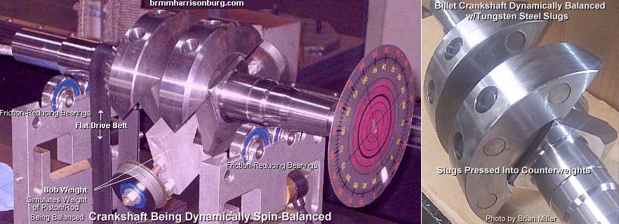 A cast or billet steel crankshaft
should survive as high as 7,000 RPM for a long time if they've been
precision-balanced to the connecting rod and piston assembly using a dynamic
balancing machine. Some cast cranks break, and steel crankshafts are prone
to breaking, too. When they do break, it's usually due to: being in an engine
that broke the connecting rod and the rotating assembly came to a "sudden
stop", and the flywheel kept wanting to spin, but cracked the crank instead;
an out-of-balance flywheel; and/or an out-of-balance starter pulley on the
PTO end (which should also be precision-balanced). An out-of-balanced flywheel
or pulley will cause the crankshaft to flex a few thousands of an inch at
open RPM. When they flex, the "bending of the metal" cause metal fatigue,
which creates a microscopic crack next to the rod journal, and they eventually
break. Kind of like bending a piece of wire back and forth by hand, until
it eventually breaks. We heard that the Kohler Magnum crankshafts are tougher
than the early K-series cranks when precision-balanced. And when a crankshaft
breaks at open RPM, it can also break a cast cam or bend a billet steel cam,
which could crack the engine block at the cam pin on the flywheel side.
A cast or billet steel crankshaft
should survive as high as 7,000 RPM for a long time if they've been
precision-balanced to the connecting rod and piston assembly using a dynamic
balancing machine. Some cast cranks break, and steel crankshafts are prone
to breaking, too. When they do break, it's usually due to: being in an engine
that broke the connecting rod and the rotating assembly came to a "sudden
stop", and the flywheel kept wanting to spin, but cracked the crank instead;
an out-of-balance flywheel; and/or an out-of-balance starter pulley on the
PTO end (which should also be precision-balanced). An out-of-balanced flywheel
or pulley will cause the crankshaft to flex a few thousands of an inch at
open RPM. When they flex, the "bending of the metal" cause metal fatigue,
which creates a microscopic crack next to the rod journal, and they eventually
break. Kind of like bending a piece of wire back and forth by hand, until
it eventually breaks. We heard that the Kohler Magnum crankshafts are tougher
than the early K-series cranks when precision-balanced. And when a crankshaft
breaks at open RPM, it can also break a cast cam or bend a billet steel cam,
which could crack the engine block at the cam pin on the flywheel side.
How to Get More Power Out of a Stock Engine -
 It takes three things to make
an internal combustion engine run: compression (air pressure within the
combustion chamber), carburetion (fuel in the carburetor) and ignition (spark).
The engine needs to have sufficient compression to fully compress the air/fuel
mixture to make adequate power. Fuel needs to get to the carburetor and then
into the combustion chamber. And the ignition needs to be strong enough to
ignite the air/fuel mixture. The ignition timing must also need to be set
correctly to ignite the air/fuel mixture precisely at 20° BTDC (Kohler)
to take full advantage of the exploding gases. Actually, it takes four things
to make an engine run, including the starting system. If an engine won't
crank over or if it cranks over slowly (with an electric
starter motor), and
it has adequate compression, the carburetor and ignition seems to be working
fine, then the only thing left is the starting system. Perhaps the starter
motor or battery is going bad. They probably appear to be operating normal,
but maybe one or the other isn't cranking the engine over fast enough to
produce adequate compression to start the engine. I've seen this happen a
few times. But if the compression, carburetion or ignition is weak or defective,
power will be decreased dramatically. When checking for loss of power, always
check the following things:
It takes three things to make
an internal combustion engine run: compression (air pressure within the
combustion chamber), carburetion (fuel in the carburetor) and ignition (spark).
The engine needs to have sufficient compression to fully compress the air/fuel
mixture to make adequate power. Fuel needs to get to the carburetor and then
into the combustion chamber. And the ignition needs to be strong enough to
ignite the air/fuel mixture. The ignition timing must also need to be set
correctly to ignite the air/fuel mixture precisely at 20° BTDC (Kohler)
to take full advantage of the exploding gases. Actually, it takes four things
to make an engine run, including the starting system. If an engine won't
crank over or if it cranks over slowly (with an electric
starter motor), and
it has adequate compression, the carburetor and ignition seems to be working
fine, then the only thing left is the starting system. Perhaps the starter
motor or battery is going bad. They probably appear to be operating normal,
but maybe one or the other isn't cranking the engine over fast enough to
produce adequate compression to start the engine. I've seen this happen a
few times. But if the compression, carburetion or ignition is weak or defective,
power will be decreased dramatically. When checking for loss of power, always
check the following things:
 Check the ignition
timing. If the timing is retarded or over advanced, the engine will lose
power and run sluggish. Check for a worn
points lobe on the camshaft, too.
Check the ignition
timing. If the timing is retarded or over advanced, the engine will lose
power and run sluggish. Check for a worn
points lobe on the camshaft, too.
Carburetion is
when the adequate amount of fuel and air mixture enters an engine smoothly.
Compression is when the air/fuel mixture is
adequately pressurized in the combustion chamber on the compression stroke.
The secret to gaining more horsepower and torque is increase the compression
ratio and improve the air flow in and out of the combustion chamber.
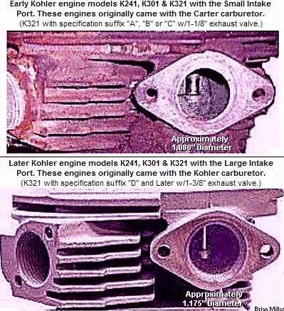 Another way to gain more power from the high RPM is to install a special
camshaft along with larger diameter
valves,
professional valve job, stiffer
valve springs and enlarge intake and exhaust
port runners.
Another way to gain more power from the high RPM is to install a special
camshaft along with larger diameter
valves,
professional valve job, stiffer
valve springs and enlarge intake and exhaust
port runners.
Apply
J-B Weld (apply at room temperature, allow to fully
cure in 24 hours) inside the intake port and smooth it so the air will flow
without any restrictions into the combustion chamber. This works great. But
before applying the J-B Weld, make sure the port is absolutely clean or the
J-B Weld will not bond to the engine block.
and a few other things that's mentioned elsewhere
in my pulling tips web sites.
FYI - When everything that's mentioned here is performed to an engine, it should produce maximum power. But if just a few things are performed, the power will be increased, but not to the maximum. For example: if a quality valve job is performed, then the intake and exhaust runners would also need to be enlarged, and the carburetor would need to be bored to take full advantage of the maximum airflow. But if the intake runner isn't enlarged, this would create a "bottle neck," and air will be restricted. The same goes for the valves and carburetor. Also, if a cam with more duration is installed, then the valve and air intake system would need to be maximized to take full advantage of the performance camshaft. But if just the cylinder head is milled, and nothing else is done to the engine, this alone should add a few ponies to an engine. The same goes when just popping the piston out of the cylinder. Each time a performance thing is done to an engine, power output will be increased. But if a series of things are performed, such as maximizing the air intake system, they can work together for better engine performance.
When it's time to put more muscle in an engine...
In order for an engine to turn at extremely high RPM (6,000+), the compression ratio and air flow in and out of the combustion chamber must be increased to the maximum. The secret to increased engine performance is to get as much air (and fuel) into the combustion chamber, and get it out as quickly as possible. (Remember - engine performance is entertainment to the spectators.) For the compression ratio to be increased, the air entering the combustion chamber must be squeezed as tight as possible.
The only things that can cause an engine to overheat and loose power are as follows:
Get Maximum Horsepower and Torque from a "Basically Stock" Kohler 10-16hp K-series or Magnum Engine -
Approximately 48% more horsepower and torque can be produced from a basically "stock" single cylinder flathead Kohler engine. This means that approximately 15hp can be produced from a 10hp, 17hp from a 12hp, 20hp from a 14hp and 23hp from a 16hp governed engine at 4,000± RPM (the factory setting of maximum RPM for virtually all small gas engines, including all of Kohler engines is 3,600) on Premium gasoline! And if a steel flywheel is used, this will add more torque to a 4,000± RPM pulling engine! Also, about 10% to 13% more power can be produced with E-85 or methanol fuels! Click or tap here for information regarding E-85 fuel. And even more power can be produced above 4,000± RPM! But be sure to install a billet steel flywheel, connecting rod and scatter shields whenever running an engine above 4,000± RPM! The compression ratio must be increased in order to increase the power output. Click or tap here for references to various compression ratios. After modifications have been made, the increase in power will definitely be noticeable!
(Added 3/3/21) To increase the compression ratio on a Kohler engine model K241, M10, K301, M12, K321, M14, K341 or M16, mill the head just until the ridge is gone. And if also decking the block, remove only enough metal where the highest part of the valve seats will not be interfered with. Higher compression ratio means more horsepower and torque, which means a more efficient engine. High octane gas may need to be used to prevent harmful pinging and detonation.
For competition pulling only, remove or disable the operation of parasitic accessories from the engine (which robs horsepower and cause drag on the engine), such as the starter/generator or alternator charging system, and including reducing the height of the fins by about 3/4 on the flywheel. Click or tap here to learn how to do this. And depending on battery drainage and need for recharging, to be precise, and with the engine running at 3,600 RPM, the generator part of the starter/generator unit or alternator stator use about 3/8hp (of engine power) when it recharges a fully discharged battery at full 15 amps; about 5/8hp at full 20 amps; and about 7/8hp at full 30 amps. But if the battery doesn't need much recharging, the charging system draws less hp from the engine. We know this small amount isn't much, but every hp counts in competition pulling. So to reserve this power for pulling, disconnect the generator or alternator from charging the battery (and powering other accessories as well) simply by splitting the wire that connects to the FIELD terminal (the smaller wire and terminal) on a s/g unit and splitting the wire that connects to the center terminal on the voltage rectifier/regular of an alternator system. Then connect an ordinary OFF/ON toggle switch in that wire or circuit to turn off and on the charging current. And it'll be best not to spin the s/g when pulling. Being it has radial ball bearings, the excessive spinning won't hurt it. But being the V-belt cause drag, depending on belt tension, it can use up to 2hp of engine power just to spin it. This is also power that can be put to the rear tires for pulling. Besides, wouldn't it be better to spin the tires than the starter/generator? So to disengage the s/g belt, install threaded studs with locknuts on the s/g bracket and install a heavy spring on the s/g so it'll remain close to the engine. To crank the engine, install the belt on the pulleys, then pull out on the s/g with a fabricated handle to tighten the belt. After the engine starts, release the s/g and flip the belt off. But use caution doing this for an obvious reason!
Briggs & Stratton, Tecumseh, Onan and Kohler's cast iron block 7hp and 8hp, and the opposed twin cylinder flathead engines are all somewhat limited on what can be done to boost their horsepower and torque. These engines are built from the factory to produce as much power as they possibly can, and still run safely on low octane gasoline. Therefore, very few modifications can be perform to help increase the power output. The only alternative is to use a bigger engine.
The increase in the compression will cause the combustion chamber to operate at a higher temperature. If low octane gas (87 octane) is used, and because low octane gas burns more rapidly than high octane gas, it'll burn hotter in a high compression engine, causing the piston and rings to overheat and wear out much sooner. Therefore, high octane gas (at least 91 octane [Premium]) must be used in a high compression engine because it burns slower and it maintains a cooler operating temperature within the combustion chamber. It'll help the engine last longer plus the high octane gas will help to produce more power. Also, it's safe to use just ordinary unleaded [high octane] gasoline with no additives (except what's already been formulated with the gasoline at the pump). Premium gasoline is the highest octane automotive gas you can get at your local filling station or convenience store.
High compression engines naturally operate at a higher operating temperature. So when using low octane gasoline (87 octane rating) in a high compression engine, the octane of the gas is reduced by 1 point for every 10º above the operating combustion chamber temperature that it is formulated for. This will cause the gas to burn faster and cause the engine to lose power. "Detonation" (pounding of the piston) could also occur. When trying to restart an overheated high compression engine on low octane gas, what is happening is the gas is burning quickly and entirely in the combustion chamber, and producing expanding heat before the piston reaches TDC, driving the piston back down in the cylinder before it reaches TDC. It'll cause the engine to "runt, runt" or momentarily make the crankshaft rotate in the opposite direction (but the weight of the flywheel prevents this from happening). Overheating could also crack the [cast iron] cylinder, shrink the piston, burn a hole in the piston (detonation) and weaken the expansion of the piston rings. Methanol fuel has an octane rating of 135. This is why methanol works best in high compression engines.
If you have a stock, low compression engine, then it won't benefit whatsoever from using high octane fuel. All it'll do is waste fuel (some of the fuel will go unburned and exit out the exhaust) and the engine won't develop full power, even with advanced timing. So it's best just to use low octane fuel for best performance.
In an ordinary engine that's built-to-factory-specs (with no modifications), it's OK to use just 87 octane gasoline. If you were to use high octane gas in a low compression engine, you'll just be wasting money and gas. Because some of the gas will go out the exhaust unburned, with no increase in horsepower whatsoever.
 As a matter
of fact, since 1969, ALL Briggs & Stratton flathead aluminum block engines
are built-to-the-max at 3,600 RPM at the factory. This does not lessen the
longevity of the engine. The B&S flathead opposed twin cylinder engines
(and all B&S single cylinder engines) have a factory-installed
performance-ground camshaft with increased duration/overlap. This is why
the opposed twin cylinder engines produce a "lopey" sound at slow idle out
the exhaust. (Lope, lope, lope sound.) There are very few improvements that
can be made to B&S engines so they will produce more horsepower and torque
at 3,600 RPM. Why Kohler didn't follow B&S's method of building engines,
I have no idea.
As a matter
of fact, since 1969, ALL Briggs & Stratton flathead aluminum block engines
are built-to-the-max at 3,600 RPM at the factory. This does not lessen the
longevity of the engine. The B&S flathead opposed twin cylinder engines
(and all B&S single cylinder engines) have a factory-installed
performance-ground camshaft with increased duration/overlap. This is why
the opposed twin cylinder engines produce a "lopey" sound at slow idle out
the exhaust. (Lope, lope, lope sound.) There are very few improvements that
can be made to B&S engines so they will produce more horsepower and torque
at 3,600 RPM. Why Kohler didn't follow B&S's method of building engines,
I have no idea.
If you need even more power, remember the old saying: "There's No Substitute for Cubic Inches!" (This is true only when the engine is naturally-aspirated, and not turbo- or super-charged.)
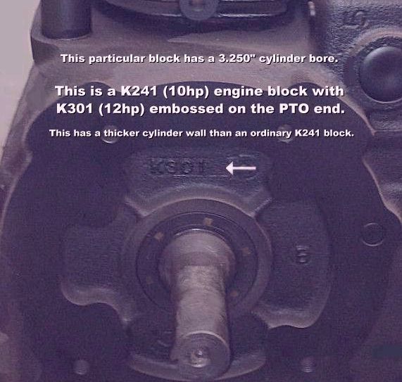 If you're running a K241 or M10
Kohler engine in a class that allow up to a K301 or M12 engine, there's no
need to go out and acquire a K301 or M12 block, and then have all the fancy
machine work that was originally done on the K241 or M10 block. Instead,
a 10hp (K241 or M10) can be easily converted into a 12hp (K301 or M12) engine
by having the cylinder bored for a K301 or M12 piston assembly. A K301 or
M12 crankshaft with a K301, M12, K321, M14, K341, M16 or K361 connecting
rod will need to be used.
If you're running a K241 or M10
Kohler engine in a class that allow up to a K301 or M12 engine, there's no
need to go out and acquire a K301 or M12 block, and then have all the fancy
machine work that was originally done on the K241 or M10 block. Instead,
a 10hp (K241 or M10) can be easily converted into a 12hp (K301 or M12) engine
by having the cylinder bored for a K301 or M12 piston assembly. A K301 or
M12 crankshaft with a K301, M12, K321, M14, K341, M16 or K361 connecting
rod will need to be used.
NOTE: Certain K-series K241 Kohler engine blocks have K301
 embossed in the casting on the PTO
end, but the engine actually have a K241 (10hp) bore and stroke. Kohler used
the K301 blocks for K241 engines when they ran out of K241 blocks to keep
up with the demand from small engine equipment manufacturers. These particular
blocks have a thicker cylinder wall and can be safely bored for a K301 or
M12 piston (even up to .040" oversize), without making the cylinder wall
too thin. They cannot be bored for a K321 or M14 piston though. Being the
10hp and 12hp engines appear virtually the same on the outside, the only
way to truly tell if this block or engine is actually a 10hp or 12hp is to
accurately measure the bore and stroke. The 10hp's STD bore is 3.250" and
the stroke is 2.875". The 12hp's STD bore is 3.375" and the stroke is 3.250".
And besides the K241 and K301 pistons being different, the K241 and K301
crankshafts and connecting rods are totally different. They will NOT interchange.
embossed in the casting on the PTO
end, but the engine actually have a K241 (10hp) bore and stroke. Kohler used
the K301 blocks for K241 engines when they ran out of K241 blocks to keep
up with the demand from small engine equipment manufacturers. These particular
blocks have a thicker cylinder wall and can be safely bored for a K301 or
M12 piston (even up to .040" oversize), without making the cylinder wall
too thin. They cannot be bored for a K321 or M14 piston though. Being the
10hp and 12hp engines appear virtually the same on the outside, the only
way to truly tell if this block or engine is actually a 10hp or 12hp is to
accurately measure the bore and stroke. The 10hp's STD bore is 3.250" and
the stroke is 2.875". The 12hp's STD bore is 3.375" and the stroke is 3.250".
And besides the K241 and K301 pistons being different, the K241 and K301
crankshafts and connecting rods are totally different. They will NOT interchange.
A K301 embossed block with the smaller K241 (10hp) 3-1/4" bore can be safely bored oversize for use with a larger K301 3-3/8" piston and rings assembly, connecting rod and crankshaft. The K301 embossed blocks are actually a K241 engine with the 10hp 3-1/4" bore, with a K241 piston and rings assembly, connecting rod and crankshaft. The only thing special about this blocks is they have a thicker cylinder wall, and they weren't used in any "heavy duty" specific application. What happened is on the production line at Kohler, when Kohler ran out of K241/10hp blocks, they grabbed some K301 blocks and bored them for use with a K241/10hp piston and rings assembly, connecting rod and crankshaft to fill the production of 10hp engines to their equipment manufacturer clients. But not all K301 embossed Kohler blocks are actually K241/10hp engines. Some are bored for a K301 3-3/8" piston and rings assembly, connecting rod and crankshaft, and therefore, are a true K301/12hp engine. To determine which block is which, the diameter of the cylinder bore must to be accurately measured, because there is no indications on the outside of the block to identify the engine size, unless it has the original flywheel shroud and adhered vinyl label or riveted metal tag with the engine model number.
How to Calculate the Horsepower of a Small Engine and Determine Its Model Number - [Top of Page]
To calculate the factory-rated horsepower (HP) of a small engine, for an average single cylinder flathead (valves in block) engine, divide the CID by 2.45, which will show the approximate HP (at 3,600 RPM), for an average two cylinder flathead engine, divide the CID by 2.41 x 2, which will show the approximate HP (at 3,600 RPM), and for the average over head valve (OHV) engine, divide the CID by 1.45 x 2 (for two cylinder engines), which will show the approximate HP (at 3,600 RPM). Once you know this, you can then determine the engine model number.
For the mathematical formulas below to work, have
JavaScript enabled in your web browser. Or use a handy
calculator  ,
or use a pen or pencil and paper
,
or use a pen or pencil and paper
 .
.
Convert Cubic Inch Displacement (CID) into Cubic Centimeters (CC)
Multiply the CID by 16.39 = Cubic Centimeters. (1 cubic inch = 16.3870641 cubic centimeters.) Example: 262.37 (CID) x 16.39 = 4300 CC. To convert CC back into CID: 1 cubic centimeter = 0.0610237 cubic inches. (1 cubic inch = 16.39 cubic centimeters)

How to Calculate the Compression Ratio of a Flathead or OHV Engine -
How to Create a 27 CID Hybrid Kohler Engine Model
K271 (Stroker K241 or M10 Engine) -
To create a 27 CID hybrid Kohler engine model K271 (Stroker 10hp), the parts to use are:
This combination of parts will create a 27 cubic inch engine, or hybrid model
K271, or a "stroker 10hp engine." With a STD size [10hp] piston, this engine
will have a 3.250" bore and 3.250" stroke, resulting in a 26.96 cubic inch
displacement engine. For strength and durability, especially if it's built
to the max, it's best to use a model K241 block with K301
If this engine is built in stock form, it should produce about 19hp and 25 ft. lb. of torque at 4,000± RPM. But if built to the max at open RPM with a quality valve job, ported, big performance cam and bored-out 1.2" and reworked carburetor, it'll produce about 29hp at 7,000 RPM and 22 ft. lb. of torque at 6,000 RPM Here's how to make it happen:
|
How to Create a 25.7, 27.7, 31.6 CID Hybrid Kohler Engine Model K261,
K281 or K321 -
To create a 25.7, 27.7 or 31.6 CID hybrid Kohler model K261 (Destroked 12hp), K281 (Destroked 14hp), or K321 (Destroked 16hp) engine, the parts to use are:
This combination of parts will create a de-stroked K301, M12, K321, M14 or K341 Kohler engine. The K261 will use a K301 or M12 block; the K281 will use a K321 or M14 block, and the K321 will use a K341 or M16 block. NOTE: If an ordinary K241 block is bored for use with a K301 piston and rings, this would leave the cylinder wall about 1/8" thick, and the cylinder could separate from the crankcase resulting in an engine explosion on a cool night when the air is dense. Therefore, if a 10hp block is used, it's highly recommended that a cylinder restraint strap be installed to secure the cylinder to the crankcase. If the hybrid model K261 is built to the max at 4,000± RPM, it should produce about 16½hp and 23 ft. lb. of torque at 4,000± RPM. And if built to the max at open RPM with a high flow valve job, ported, big performance cam and bored-out and reworked 1.2" carburetor, it'll produce about 26hp at 7,500 RPM and 22 ft. lb. of torque at 6,000 RPM. If the hybrid model K281 is built to the max at 4,000± RPM with stock size valves, ported, quality performance torque cam and a bored-out and reworked 1.2" carburetor, it'll produce about 22hp and 28 ft. lb. of torque at 4,000± RPM. And if built to the max at open RPM with a high flow valve job, ported, big performance cam and bored-out and reworked 1.2" carburetor, it'll produce about 30hp at 7,000 RPM and 25 ft. lb. of torque at 6,500 RPM. If the hybrid model K321 (by the way - this is NOT for the original K321/14hp Kohler engine) is built to the max at 4,000± RPM with a quality valve job, ported, quality performance torque cam and a bored-out and reworked 1.2" carburetor, it'll produce about 25hp and 33 ft. lb. of torque at 4,000± RPM. And if built to the max at open RPM with stock size valves, ported, big performance cam and bored-out and reworked 1.2" carburetor, it'll produce about 36hp at 7,500 RPM and 30 ft. lb. of torque at 6,000 RPM. Here's how to make it happen:
|
How to Create a 36.7, 38.3, 39.5 or 40.8 CID Hybrid Kohler Engine Model
K381 or K411 -
Use a K321, M14, K341, M16 or K361 stock stroke crankshaft. These cranks require less ballast weight for balancing, than using a K301 or M12 crankshaft, which would require A LOT MORE ballast weight for balancing. The K341 or M16 engines have a STD bore of 3.750". But with the Chevy V8 307 STD size (3.875") piston, the Kohler block will have an 1/8" overbore. With the Chevy V8 307 .060" oversize (3.9375") piston, it'll have a 3/16" overbore. And with the Chevy V8 327 STD size (4.000") piston, it'll have a 1/4" overbore. The 307 and 327 piston, rings and wrist pin are available at most auto parts supply stores. Coincidentally, the Chevy 307 and 327 engines have the same stroke as the Kohler K301, M12, K321, M14, K341, M16 and K361 engines, which is 3.250". The K341 or M16 engines with a STD size 3-3/4" Kohler piston, stock 3.250" stroke crankshaft and stock head, they have a compression ratio of 7.4:1. But with a STD size 3-7/8" 307 piston, a stock stroke crankshaft and stock head, the compression ratio will be 7.7:1. And with a STD size 4" 327 piston, a stock stroke crankshaft and stock head, the compression ratio will be 8:1. If the 38.3 CID engine is built to the max at 4,000± RPM with a quality valve job, enlarged intake and exhaust runners, a quality performance torque cam and a bored-out and reworked 1.2" carburetor, it'll produce about 28hp and 37 ft. lb. of torque at 4,000± RPM. And if the 40.8 CID engine is built to the max at 4,000± RPM with a quality valve job, enlarged intake and exhaust runners, a quality performance torque cam and a bored-out and reworked 1.2" carburetor, it'll produce about 30hp and 39 ft. lb. of torque at 3,500 RPM. Here's how to make it happen:
|
How to Build a 30 Cubic Inch (NQS Outlaw) Pulling Engine -
To build a competitive 30 cubic inch pulling engine, acquire a later model K301 or M12 Kohler block with a large intake port, have the cylinder bored to .050" oversize for a 3.425" aftermarket (J&E or Arias) piston/rings assembly, and use a stock stroke (3.250") crankshaft. This bore and stroke combination calculates to 29.94 c.i. (Install a 1.8" offset intake valve and a 1.5" offset exhaust valve, big steel cam, billet head, and use a 44mm Mikuni carburetor with about an 8" length extension.) The piston and rod combination to use for this particular bore and stroke are as follows:
But to build a truly competitive 30 c.i. pulling engine, use a 10hp/K241
Kohler block with K301
The longer stroke works better for more torque at high RPM. Due to the small bore and long stroke, this combination produces more torque (lugging power) at open RPM than building a K301 or M12 engine with a .050" overbore and stock stroke (3.250") crankshaft. If the engine is built correctly, and if the correct camshaft and gearing is used, it'll give the competition a kick in their butt! No joke. Use the same size valves, cylinder head and carburetor as the stock stroke engine above È. This bore and stroke combination is legal in the NQS's rules, as long as the cubic inch displacement does not exceed 30. With the 3.300" bore and 3.500" stroke, the cubic inches will be 29.94. But to be closer to 30 cubic inches, have a STD size crank journal ground .015" offset, resulting in a .030" undersize journal, lengthening the stroke to 3.5075". The results with the 3.300" bore and a 3.5075" stroke, the cubic inches will be 29.999, which is slightly under the legal limit. Doing this will gain an edge over the competition. Click or tap here for an explanation of why a longer stroke works better. |
Gain More Power and Torque by Moving the [16hp] Piston Closer to the Valves!
Only the OEM 16hp (K341) and 18hp OHV (K361) Kohler engine blocks, the center of the cylinder bore is offset .250" (1/4") with the centerline of the crankshaft main radial ball bearings. Because of the much larger bore, the piston is moved further away from the valves. On OEM pistons, the wrist pin is also located off-center .010" so they'll be less thrust (friction) on the cylinder wall, and this will allow the connecting rod to operate correctly. That's why these particular pistons have a notch in them indicating that the notch must face toward the flywheel.
In a high-performance 16hp engine, if the cylinder is bored in its original location (when the piston is installed off-center), and at open RPM, this will create a lot of friction in the area of the cylinder wall that's closest to the valves. To minimize or reduce this power-wasting friction, have the cylinder bored inline or centered with the center of the main radial ball bearings, or closest to the center of the main radial ball bearings as possible, depending on the diameter of the piston to be installed. More compression will be produced by doing this, too.
The best way to do this is acquire a [13 fin] 16hp block with an unworn, standard size cylinder. The reason it's best to use an unworn, standard size cylinder is for example, if a 3.825" (.075" oversized) diameter piston is going to be used, the cylinder will need to be bored .030" closer to the valves. The piston will then travel .030" closer with the main radial ball bearings. The piston still wouldn't be centered, but it'll be closer than the 1/4" offset. Larger diameter pistons may not be moved this close to the valves though. But it will help greatly in the performance characteristics.
All Kohler K-series and Magnum models K241, M10, K301, M12, K321 and M14
engine blocks have 13 cooling fins. Otherwise, there's really nothing else
special about these blocks. Except for certain K-series K241 blocks that
have K301 embossed on the PTO end,
which have a thicker cylinder wall. These blocks works best for the 30 cubic
inch class pulling tractors with a stroker engine.
Differences Between the 12 fin and 13 fin 16hp OEM Kohler blocks, and the (Kohler-Replicated 16hp) Aftermarket Blocks -
 The 12 fin 16hp Kohler K-series
K341 and Magnum M16 engine blocks have a curved indentation in the cooling
fins (clearance for a straight oil fill/dipstick tube) and a threaded hole
at the bottom of the cylinder. Count the number of fins from the PTO end
of the block. These blocks have a thinner cylinder wall than the 13 fin block.
These blocks are most commonly used for light duty lawn and garden equipment
applications, and when used for a competition pulling application, can be
safely bored up to a 3.937" piston without danger of seriously weakening
the support of the cylinder wall. A cylinder
restraint strap is highly recommended, especially when burning methanol
fuel.
When using a billet
connecting rod, being all of these rods have a short oil dipper, it's best
to use a flat bottom oil pan for sufficient oiling of the internal parts
inside the engine if or when the oil level gets low.
The 12 fin 16hp Kohler K-series
K341 and Magnum M16 engine blocks have a curved indentation in the cooling
fins (clearance for a straight oil fill/dipstick tube) and a threaded hole
at the bottom of the cylinder. Count the number of fins from the PTO end
of the block. These blocks have a thinner cylinder wall than the 13 fin block.
These blocks are most commonly used for light duty lawn and garden equipment
applications, and when used for a competition pulling application, can be
safely bored up to a 3.937" piston without danger of seriously weakening
the support of the cylinder wall. A cylinder
restraint strap is highly recommended, especially when burning methanol
fuel.
When using a billet
connecting rod, being all of these rods have a short oil dipper, it's best
to use a flat bottom oil pan for sufficient oiling of the internal parts
inside the engine if or when the oil level gets low.
Here's something to think about: Between the factory-stock K301, M12, K321 and M14 engines, there's 2.19 cubic inches of difference. This means you get 2 more horsepower for that much difference. But between the stock 14hp and 16hp engines, there's a whopping 4.63 cubic inches of difference, for just 2 more horsepower! The reason for this is because the friction that the piston place against the cylinder wall in the 16hp robs the engine of valuable power. Kohler had to add more cubic inches just to get a maximum of 16hp out of their K341 engine at 3,600 RPM.
And if you're wondering, the cylinder bore is centered in all the [Jones, Julian, etc.] aftermarket blocks.
Do not attempt doing the above
È on the K241, M10, K301, M12, K321
or M14 engines! The cylinder on these engines are bored centered with the
centerline of the main radial ball bearings. Which should remain this way
even for a pulling engine.
Is it worth it moving the piston in a 16hp Kohler?
Engines that use a piston or pistons with a notch have an offset wrist pin.
The factory had to do this on a lot of big bore engine blocks because the
cylinder bore is offset with the crankshaft main radial ball bearing centerline.
To lessen wear on one side of the piston, the offset wrist pin allow the
piston to operate straight up and down in the cylinder and not at an angle.
If it can be done, then it's definitely worth moving the bore closer to the centerline of the main radial ball bearings. The aftermarket Stock-Altered block has the bore in the stock location (.250" off of the centerline of the crank, toward the starter side of the engine) and is not centered like some must think. Most all the NQS S/A have the bores shifted closer to the valves. By doing this you end up with a tighter combustion chamber for more compression and power. We've done it for a long time on the stock Kohler blocks by offset boring the engine toward the valves, then pressing in a sleeve and offset boring the sleeve for proper fit of the piston and rings. You have to leave about .100 to .125 wall thickness on the sleeve on the valve side to maintain the strength. Depending on how far you move it, the sleeve will show between the fins between the valve box and jug. However, its cheaper just to buy the S/A block and offset bore that, the unfinished bore of a S/A block is only about 3-1/2" so you can offset it quite a bit and still get the bore to cleanup. I paid around $1,000 to sleeve and offset bore an original Kohler block, but it can be done. As far aftermarket blocks that have the bores center over the crank is the Pro/Super Stock blocks like the J2 and others. - This information was provided by my friend, Julian Stahl of Midwest Super Cub. |
Why a Longer-Than-Stock Stroke Works Better For More Lugging Power and/or Competition Pulling -
 Many people (pullers) believe
that an engine will produce more noticeable power (speed) and torque (lugging
power) simply by boring the cylinder and installing a maximum of .030" oversize
piston and rings assembly. There's no need for this and it will not help
the engine to produce anymore noticeable power. The cylinder should be bored
oversize only if it's worn beyond specifications or scored. Or if the cylinder
is max'd out at .030" and became worn, it can be either be bored for an
aftermarket .040" oversize piston and rings assembly. This size piston and
rings is available only for the K301, M12, K321, M14, K341, M16 and K361
[OHV] engines. Or the cylinder can be sleeved for a STD
for a size piston and rings assembly. See my list of available STD size,
.010", .020", .030" and .040" oversize piston and rings further down in this
web site. Ê
Many people (pullers) believe
that an engine will produce more noticeable power (speed) and torque (lugging
power) simply by boring the cylinder and installing a maximum of .030" oversize
piston and rings assembly. There's no need for this and it will not help
the engine to produce anymore noticeable power. The cylinder should be bored
oversize only if it's worn beyond specifications or scored. Or if the cylinder
is max'd out at .030" and became worn, it can be either be bored for an
aftermarket .040" oversize piston and rings assembly. This size piston and
rings is available only for the K301, M12, K321, M14, K341, M16 and K361
[OHV] engines. Or the cylinder can be sleeved for a STD
for a size piston and rings assembly. See my list of available STD size,
.010", .020", .030" and .040" oversize piston and rings further down in this
web site. Ê
An engine with a small bore and long stroke works best for more engine torque because at very open RPM, in an engine with a small bore and long stroke, it takes less time for the flame front (combustion pressure) to travel down in the cylinder than it would to travel across the top of the piston in an engine with a large piston and short stroke. Therefore, due to the longer stroke, the fuel burns more thoroughly and the engine produces more torque (lugging power) from the expanding gases of the burning fuel. For competition pulling, with a short stroke engine, at very open RPM, and when the engine is under a load, some of the fuel will go unburned and out the exhaust, and the engine will lack full power. Race car engines and tractor pulling engines are not built on the same principles. A large bore and short stroke engine works best for lightweight racing applications, but definitely not for pulling heavy loads. Racing engines require horsepower to produce more speed, and pulling engines require torque to produce more lugging power. This applies to all piston-powered engines, despite if it's a gas/alcohol burner, Diesel, 2- or 4-cycle. This is also why some "cheaters" in pulling competition like to run an illegal "stroker engine" in a class that require a stock stroke engine. As a result, on a biting track, when all the legal [stock stroke] tractors have run out of power, the tractor with the stroker engine will keep lugging out the gate or on to victory.
 What makes more torque (lugging
power) is an engine with a long stroke (longer than the bore size; from the
factory) or building an engine so it will have a longer stroke by installing
a crankshaft with a longer stroke, shorter connecting rod and piston with
a higher compression height. For example: there's a world of difference
in torque between the Kohler K241/M10 (10hp engines), and the K301/M12 (12hp
engines). Unlike a healthy K241, a K301 or M12 in excellent condition that's
in a garden tractor when quickly accelerated or revved up will literally
"pull you back in the seat." This is an example of what engine torque does.
It has a lot of lugging power. The powerful acceleration is because not only
does the 12hp have an 1/8" larger cylinder bore than the 10hp, but it has
a much longer crankshaft stroke, 3/8" longer to be exact. Plus, the 12hp
engine has a higher compression ratio than the 10hp
(when the same type of cylinder head
is used). In stock form, the 12hp engine is capable of producing 2 more
horsepower than the 10hp because of three things: 1) 1/8" larger bore, 2)
3/8" longer stroke, and 3) higher compression ratio. But there's not really
that much of a noticeable difference in power and torque between the 12hp
and a K321 (14hp) engine, because the 14hp has an 1/8" larger bore, but it
has the same length stroke as the 12hp. 14hp engines are able to produce
2 more horsepower than the 12hp because of two things: 1) 1/8" larger bore,
and 2) higher compression ratio because they use the same cylinder head with
the same size combustion chamber as the 12hp (and 10hp). Another example
is the Kohler K141 (6.6hp, K161 (7hp) and K181/M8 (8hp) engines. Besides
the smaller bore on the early K141 and K161 engines, these are virtually
identical in every way except for the length of the stroke. The K141 and
K161 have a crankshaft stroke of 2.500", and the 8hp's crankshaft stroke
is 2.750". A 1/4" longer stroke (and higher compression due to the same cylinder
head) results in 1hp more. The Kohler opposed twin cylinder engine, KT17
(first design), KT17 Series II, MV16, M18 and MV18 (which are basically made
identical) have a crankshaft stroke of 2.750", and the KT19 (first design),
KT19 Series II, KT21, M20 and MV20 (which are also basically made identical)
engine's crankshaft stroke is 3.063", resulting in about .313" (5/16" or
8mm) difference. The longer stroke is basically the main difference between
these engine models. The 5/16" difference in stroke give the bigger engines
(KT19/M20/MV20) 2 more horsepower. Many new automotive engines in heavier
vehicles nowadays (mainly trucks) have a small cylinder bore and long crankshaft
stroke. (Remember Ford's "Power Stroke" truck engine? And GM's LS engines?
Simply because these work better for hauling heavy loads at higher RPM.)
Return to previous paragraph
È
What makes more torque (lugging
power) is an engine with a long stroke (longer than the bore size; from the
factory) or building an engine so it will have a longer stroke by installing
a crankshaft with a longer stroke, shorter connecting rod and piston with
a higher compression height. For example: there's a world of difference
in torque between the Kohler K241/M10 (10hp engines), and the K301/M12 (12hp
engines). Unlike a healthy K241, a K301 or M12 in excellent condition that's
in a garden tractor when quickly accelerated or revved up will literally
"pull you back in the seat." This is an example of what engine torque does.
It has a lot of lugging power. The powerful acceleration is because not only
does the 12hp have an 1/8" larger cylinder bore than the 10hp, but it has
a much longer crankshaft stroke, 3/8" longer to be exact. Plus, the 12hp
engine has a higher compression ratio than the 10hp
(when the same type of cylinder head
is used). In stock form, the 12hp engine is capable of producing 2 more
horsepower than the 10hp because of three things: 1) 1/8" larger bore, 2)
3/8" longer stroke, and 3) higher compression ratio. But there's not really
that much of a noticeable difference in power and torque between the 12hp
and a K321 (14hp) engine, because the 14hp has an 1/8" larger bore, but it
has the same length stroke as the 12hp. 14hp engines are able to produce
2 more horsepower than the 12hp because of two things: 1) 1/8" larger bore,
and 2) higher compression ratio because they use the same cylinder head with
the same size combustion chamber as the 12hp (and 10hp). Another example
is the Kohler K141 (6.6hp, K161 (7hp) and K181/M8 (8hp) engines. Besides
the smaller bore on the early K141 and K161 engines, these are virtually
identical in every way except for the length of the stroke. The K141 and
K161 have a crankshaft stroke of 2.500", and the 8hp's crankshaft stroke
is 2.750". A 1/4" longer stroke (and higher compression due to the same cylinder
head) results in 1hp more. The Kohler opposed twin cylinder engine, KT17
(first design), KT17 Series II, MV16, M18 and MV18 (which are basically made
identical) have a crankshaft stroke of 2.750", and the KT19 (first design),
KT19 Series II, KT21, M20 and MV20 (which are also basically made identical)
engine's crankshaft stroke is 3.063", resulting in about .313" (5/16" or
8mm) difference. The longer stroke is basically the main difference between
these engine models. The 5/16" difference in stroke give the bigger engines
(KT19/M20/MV20) 2 more horsepower. Many new automotive engines in heavier
vehicles nowadays (mainly trucks) have a small cylinder bore and long crankshaft
stroke. (Remember Ford's "Power Stroke" truck engine? And GM's LS engines?
Simply because these work better for hauling heavy loads at higher RPM.)
Return to previous paragraph
È
 If your association/club sanctioning
engine rules and requirements allow a longer-than-stock stroke in any particular
class, lengthen or increase the crankshaft's stroke slightly by grinding
the crank journal .030" undersize with a .015" offset. Doing this will increase
the stroke by .015". This would have to be done on an standard size, unworn
journal. If the journal is worn, the amount of wear will have to be subtracted
from the increase in stroke. Grinding the journal offset to increase the
stroke is a way to slightly increase engine performance. It won't make a
world of difference in engine performance, but it does help. Many professional
high-performance engine builders do this to gain three things:
If your association/club sanctioning
engine rules and requirements allow a longer-than-stock stroke in any particular
class, lengthen or increase the crankshaft's stroke slightly by grinding
the crank journal .030" undersize with a .015" offset. Doing this will increase
the stroke by .015". This would have to be done on an standard size, unworn
journal. If the journal is worn, the amount of wear will have to be subtracted
from the increase in stroke. Grinding the journal offset to increase the
stroke is a way to slightly increase engine performance. It won't make a
world of difference in engine performance, but it does help. Many professional
high-performance engine builders do this to gain three things:
Here's another thing to consider: half of the .015" increase in stroke is .0075". So .0075" plus the .020" offset rod adds up to .0275". Therefore, the piston will pop out of the cylinder at .0275". If the head was milled at .050", the clearance between the piston and head would be .0225". (.0275" - .050" = .0225".) This would still be a safe margin of clearance. The slightly longer stroke (Click or tap here for an explanation of why a longer stroke works better.) would help to increase the power and torque, PLUS the increase of the compression ratio with the .050" milling of the head (remove the raised ridge that mates with the head gasket) would help in power and torque, too.
 Also, a K241 and M10 block can
be bored to use a K301 or M12 piston and a K301 and M12 block be bored to
use a K321 or M14 piston, but this makes the cylinder wall very thin
(approximately 1/8" thick). And it's safe to bore a K301 10hp block for use
with a K301 or M12 piston. If an ordinary block is not going to be used for
pulling, it should be OK. But if it is going to be used for pulling, It is
highly recommended that a cylinder restraint
strap (which is sometimes called a "head restraint") be installed (cylinder
securely "fastened"-the crankcase) to prevent the possibility of
cylinder/crankcase separation, which can be a terrible experience. Also,
to maintain precision engine balance, a 14hp crankshaft must be used with
the 14hp piston.
Also, a K241 and M10 block can
be bored to use a K301 or M12 piston and a K301 and M12 block be bored to
use a K321 or M14 piston, but this makes the cylinder wall very thin
(approximately 1/8" thick). And it's safe to bore a K301 10hp block for use
with a K301 or M12 piston. If an ordinary block is not going to be used for
pulling, it should be OK. But if it is going to be used for pulling, It is
highly recommended that a cylinder restraint
strap (which is sometimes called a "head restraint") be installed (cylinder
securely "fastened"-the crankcase) to prevent the possibility of
cylinder/crankcase separation, which can be a terrible experience. Also,
to maintain precision engine balance, a 14hp crankshaft must be used with
the 14hp piston.
If methanol is going to be burned in an engine, and because the engine will have a thinner cylinder wall with increased compression, It is highly recommended that the cylinder be fastened to the crankcase, to prevent the possibility of cylinder/crankcase separation (engine explosion).
The only thing that retains the cylinder to the crankcase is the cylinder wall. If the cylinder is bored for an excessively large piston, this will make the cylinder wall extremely thin. Therefore, the purpose of the cylinder restraint strap (which is sometimes called a "head restraint"), is to prevent the CYLINDER WALL from separating from the CRANKCASE, which will result in a sudden (and possibly terrifying) engine explosion on a cool or cold day. The thicker the cylinder wall, the less chance the cylinder will separate from the crankcase.
When burning methanol fuel, with a thin cylinder wall, and if the cylinder isn't securely fastened to the crankcase, the engine will likely explode at wide open throttle while under a load on a cool night. The reason this will happen on a cool night is, because air is more dense when it's cool, making it "thicker". The colder air is, the "thicker" it becomes. (This is why it's easier to breathe on a cool day than on a hot day, or when in an air conditioned place.) Anyway, in a cool, dense-air environment, an engine, when run at wide open throttle, especially with a big cam, big ports and bigger valves, will build up more compression, placing a tremendous strain on the thin cylinder wall every time combustion occurs.
Furthermore, if you had a K241 or M10 block bored for a K301 or M12 piston, or a K301 or M12 block bored for a K321 or M14 piston, and you use your tractor to push snow, definitely securely fasten or strap the cylinder to the crankcase! Because it now has a much thinner cylinder wall, and the cold winter air is more dense (like the air is thicker or there's more of it). Dense air will build up the compression pressure within the combustion chamber, causing the engine to produce more power. But what also happens is at full throttle, this high compression is pushing upward on the cylinder head, and pulling upward on the cylinder wall. And sometimes the cylinder wall will break, ruining the whole engine. We know, we've had this happen before. No joke. Actually, it's in the foreseeable knowledge of the laws of physics on how a successful pulling engine (and entire tractor) is built. Plus, it's the combination of tractor and driver working together as one that does well at the pulls.
If a bigger flathead engine still won't give you enough power, then use an overhead valve (OHV) engine. These run circles around a flathead of the same cubic displacement, and they produce more horsepower and torque per cubic inch than any flathead engine ever will.
The Cylinder Restraint Strap (Also Called a "Head Restraint") -
 On a single cylinder competition
Kohler pulling engine that pulls at wide open throttle, when the cylinder
is bored oversize with an extremely large diameter piston, this will leave
the cylinder wall very thin. So thin in fact, under high compression, the
cylinder could break free from the crankcase, especially when burning methanol
fuel on a cool night. This have also been known to happen with competition
pulling engines burning gas, too. This usually happens on a cool night when
the air is dense.
On a single cylinder competition
Kohler pulling engine that pulls at wide open throttle, when the cylinder
is bored oversize with an extremely large diameter piston, this will leave
the cylinder wall very thin. So thin in fact, under high compression, the
cylinder could break free from the crankcase, especially when burning methanol
fuel on a cool night. This have also been known to happen with competition
pulling engines burning gas, too. This usually happens on a cool night when
the air is dense.
Therefore, to prevent this from happening (especially to a high-dollar engine), it's best to fabricate and install a sturdy cylinder restraint. Restraining the cylinder is when a strap, made of heavy gauge square steel or thick flat aluminum, is placed across the cylinder head and clamped tightly by means of two minimum 1/2" diameter heat-treated and hardened steel threaded rods (All Thread) securely welded to two flat 1/8" thickness x 1" wide T-shaped steel braces that's fastened on the PTO end of the crankcase and against the OEM Kohler bearing plate. Do not use anything smaller than 1/2" diameter threaded rods! Because smaller threaded rods, even if they are heat-treated and hardened, could break, along with the cylinder. (I've personally seen this happen several times to good pulling engines.) Anyway, one brace will need to be fastened against the bearing plate using the two upper bolts just behind the flywheel with longer, grade 8 bolts, and the other brace will be fastened to the PTO end of the crankcase with grade 8 bolts. If there are no two (minimum 3/8") threaded bolt holes present toward the upper part of the PTO end of the block, then they will need to be drilled and tapped to fasten the brace. Position the braces and threaded rods so the strap is in the middle of the cylinder head, next to the spark plug. Only one well-constructed sturdy restraint/strap is sufficient. There's no need to install two restraints/straps across the head.
Furthermore, NEVER install long threaded rods for the restraint system in the top edge of the OEM bearing plate! I've seen where some engine builders do this, and sometimes the [cast] aluminum will break, allowing the cylinder to separate from the crankcase with catastrophic results, as shown in the photo above. Therefore, it's much stronger and less machine work to use two 3/16" x 1" flat pieces of steel welded-together to create an upside-down "T". Remove the flywheel, and fasten one "T" brace using the two upper bolts on the bearing plate. The brace should clear the raised ridges on the OEM large bearing plate (for the gear starter motor). With a small bearing plate however, the ridges will need to be ground away for clearance of the brace. And there's no need to install long threaded rods directly into the crankcase to fasten the cylinder restraint to the crankcase. The other "T" brace can be fastened on the PTO end of the block with a couple of 3/8" grade 8 bolts. If there's no bolt holes for mounting of the brace, two 3/8" threaded holes will need to be drilled and tapped. Measure accurately, cut off, and align the threaded rods, and then securely weld them to the "T' braces. See the photo below. Torque the restraining nuts to 10 ft. lb. each. So strap it now, or scrap it later! Return To Previous Paragraph

 Also, due to the extreme pressure
a high torque gear
reduction starter places on the side of the block of a high compression
competition pulling engine to crank it over, it'll be a good idea to fabricate
and install a support reinforcement brace as shown in the photo to the right
to prevent the possibility of block breakage, especially if a Kohler block
have been repaired with welding as the result of a broken connecting rod.
Again, brace it now, or possibly scrap it later!
Also, due to the extreme pressure
a high torque gear
reduction starter places on the side of the block of a high compression
competition pulling engine to crank it over, it'll be a good idea to fabricate
and install a support reinforcement brace as shown in the photo to the right
to prevent the possibility of block breakage, especially if a Kohler block
have been repaired with welding as the result of a broken connecting rod.
Again, brace it now, or possibly scrap it later!
And a K301 or M12 block definitely can't be bored for use with a K341 or M16 piston because the outside diameter of the cylinder wall is too small. And it's doubtful that a K321 or M14 block can be bored for use with a K341 or M16 piston. However, some people have done this with success. In order to make this happen, being the 16hp piston is offset in the cylinder, the center of the outer part of the cylinder will need to be offset one way or the other (not like in the 16hp block) to center the bore in the block as not to break through the cylinder wall during the boring process. Boring a 14hp engine to accept a STD size 16hp piston is a tricky process. First, you must find the "center" of the cylinder. This is done by measuring the outside of the cylinder to find the thinnest and thickest parts. If this isn't done, then the boring process could break through the thin part of the cylinder wall. And if the cylinder is bored offset, the wrist pin in the piston will allow the piston to be centered with the crank journal. If attempting a 16hp piston is installed in a 14hp block, it'll be a good idea to fasten the cylinder to the crankcase rather it's for competition pulling or general lawn and garden use.
The Correct and Professional Way to Sleeve a Cylinder:
FYI: The term "resleeving" is removing a previously installed worn sleeve and installing a new one. And "sleeving" is installing a new sleeve when one wasn't already installed.
A sleeve should be installed in a block if the cylinder wall...
 If a block has a small missing
chunk at the bottom, and if the chunk isn't wide enough for the piston to
be unstable in the cylinder, then don't worry about sleeving the block. If
the cylinder wall don't need to be bored (honed) to the next oversize, just
use it as it is. As a matter of fact, pulling engines with a machined billet
rod require that the lower end of the cylinder be ground away on each side
for clearance of the wider rod. If performed correctly, this will not interfere
with the stability of the piston whatsoever. But if it's a pretty wide missing
chunk, and you have doubts about the stability of the piston, then perhaps
the block needs to be sleeved. Before installing the sleeve, the cylinder
is made bigger with a boring bar. If performed correctly, the boring bar
is adjusted so it won't cut away approximately 1/8" bottom portion of the
cylinder. The missing chunk will not interfere with the boring process either.
The boring bar machine is positioned firmly with the cylinder to prevent
any slippage. As it bores the cylinder, it'll skip over the missing chunk
and continue to bore the rest of the cylinder. Then after the sleeve is
installed, it's honed for fitting of the piston and rings.
If a block has a small missing
chunk at the bottom, and if the chunk isn't wide enough for the piston to
be unstable in the cylinder, then don't worry about sleeving the block. If
the cylinder wall don't need to be bored (honed) to the next oversize, just
use it as it is. As a matter of fact, pulling engines with a machined billet
rod require that the lower end of the cylinder be ground away on each side
for clearance of the wider rod. If performed correctly, this will not interfere
with the stability of the piston whatsoever. But if it's a pretty wide missing
chunk, and you have doubts about the stability of the piston, then perhaps
the block needs to be sleeved. Before installing the sleeve, the cylinder
is made bigger with a boring bar. If performed correctly, the boring bar
is adjusted so it won't cut away approximately 1/8" bottom portion of the
cylinder. The missing chunk will not interfere with the boring process either.
The boring bar machine is positioned firmly with the cylinder to prevent
any slippage. As it bores the cylinder, it'll skip over the missing chunk
and continue to bore the rest of the cylinder. Then after the sleeve is
installed, it's honed for fitting of the piston and rings.
How to Install a Cylinder Sleeve:
Despite
the diameter of the cylinder, the .003" interference fit makes for a perfect
press fit. Do not make it any tighter or the cylinder could split or
crack!
Maintain Proper Crankcase Vacuum and Ventilation so the Engine Will Produce More Power and Prevent Loss of Oil Through the Breather Assembly!
The reed valve or umbrella check valve are a very important part of the crankcase breather assembly on a small engine. These allow the escape of excess air pressure inside the crankcase, prevents the loss of oil through the crankcase breather assembly (as long as the engine isn't over-revved or the piston rings are in good condition), prevents outside dust and dirt from entering the crankcase, and they maintain vacuum within the crankcase and proper ventilation so the engine will produce more power and last longer. It works exactly the same as the positive crankcase ventilation (PCV) valve as the emission control in an automotive engine crankcase ventilation system since 1960.

When reinstalling the reed valve/breather plate assembly on models K141, K160/K161, L160/L161, L181, K181 and M8, the reed valve faces outward. If the reed valve on the breather plate is installed in reverse and toward the crankcase, the engine will blow excessive amount of oil out the breather assembly. And on all Kohler engine models, the small hole in the reed plate faces downward so any oil that accumulates in the breather assembly will drain back down into the crankcase. Also, if using clear RTV silicone adhesive sealant, be careful not to block or plug the oil drain hole with the sealant when reinstalling the breather plate and breather cover to the crankcase. By the way - it's best to use Clear RTV Silicone Adhesive Sealant for three reasons: Gaskets don't always seal the imperfections and irregularities between two mating metals, especially thin metal covers; being Clear RTV Silicone Adhesive Sealant is an adhesive or glue, it bonds parts together, forming a leak-proof seal; and being it's clear, it makes for a clean and professional-looking repair job. When applied sparingly, it can't be easily seen or noticed between the parts. Also, engine heat has very little effect on silicone rubber. It can withstand up to 2,500 degrees heat.
 If wishing to use a rubber hose
to route the oil vapors down and away from the engine and tractor (for
cleanliness), the louvered vent openings on the OEM Kohler crankcase breather
cover can be hammered closed, then a 7/16" hole will need to be drilled and
tapped towards the upper left corner of the cover for a 1/4" NPT
(preferably brass, for appearance reasons) elbow fitting. The reason the
hole should be towards the upper left corner is so the fitting won't interfere
with the carburetor when it is mounted directly to the engine block without
an extension, such as on a Stock, Hot Stock or Stock-Altered pulling engine.
To prevent loss of oil, do not install the cover upside-down!
If wishing to use a rubber hose
to route the oil vapors down and away from the engine and tractor (for
cleanliness), the louvered vent openings on the OEM Kohler crankcase breather
cover can be hammered closed, then a 7/16" hole will need to be drilled and
tapped towards the upper left corner of the cover for a 1/4" NPT
(preferably brass, for appearance reasons) elbow fitting. The reason the
hole should be towards the upper left corner is so the fitting won't interfere
with the carburetor when it is mounted directly to the engine block without
an extension, such as on a Stock, Hot Stock or Stock-Altered pulling engine.
To prevent loss of oil, do not install the cover upside-down!
The "filter" in the crankcase breather assembly is actually an
oil trap. It traps and suspends oil
vapors from exiting the crankcase at higher RPM, then allows the oil to drain
back down into the crankcase when the engine is at an idle or turned off.
It's too coarse to be a filter of any kind.
 It's a must for a high RPM
pulling engine.
It's a must for a high RPM
pulling engine.
When reinstalling the crankcase breather assembly on a single cylinder engine, make sure all the original components are reinstalled in the same order they were removed so that proper crankcase vacuum is maintained. This is important on any engine, especially a pulling engine. More horsepower will be created and the inside of the crankcase will stay clean longer.
Dyno tests have proven that a single cylinder engine will produce more power with the reed valve and breather plate installed. Some pullers like to use just a fabricated aluminum cover (an "aluminum valve cover" just for looks) and not the reed valve and breather plate. This is wrong because without the reed valve in the crankcase breather, with the engine running and as the piston(s) moves upward, (in a single- or two-cylinder engine) air (and dust fragments in the atmosphere) will be drawn into the crankcase through the breather cover hole. And as the piston goes back down, air will be forced out of the crankcase through the same hole. This rapid "in and out" movement of air will rob an engine of power because air must be compressed through the small breather hole. Hot air (and the hot oil vapors) are supposed to be forced out of an engine, not sucked in. And the piston will automatically vent the pressure on the downward stroke through the breather hole.
When to Use a Crankcase Vacuum Pump in a High-Performance/High RPM Engine -
A crankcase vacuum pump is a belt-driven or electrically-operated motorized pump to draw air out of the crankcase to create a vacuum, or maintain negative air pressure. A 12 volt high volume electric fuel pump can also be used as a crankcase vacuum pump with the inlet port connected to the crankcase breather and the outlet port empty into the atmosphere. Anyway, high-performance and high RPM single cylinder pulling engines don't require a crankcase vacuum pump because the backside or underneath of the piston force air out of the crankcase on it's downward stroke, and the reed valve in the crankcase breather assembly prevents air from reentering the crankcase. But high-performance and high RPM multi-cylinder engines will benefit greatly from a crankcase valve pump. With multi-cylinder engines, one or several pistons is on the downward stroke while the other piston(s) is on the upward stroke. With this configuration, no air can be forced out of the crankcase. Heat from normal engine operation cause the crankcase oil to build up pressure, and this is what relieves the pressured [hot] air from the crankcase. This is why two-cylinder small engines have a reed valve in the crankcase breather assembly, and automotive engines crankcase is vented through the valve covers. A crankcase vacuum pump will draw out all the [hot] air from the crankcase to maintain a vacuum, or negative crankcase pressure. With no air in the crankcase for the backside of the pistons to push against, a multi-cylinder engine will produce more power and torque at higher RPM.
On the cast iron block 7hp and 8hp Kohler engines, the reed plate is installed with the reed valve facing outward or towards you. This allow air to escape out the crankcase, but no air can enter into the crankcase.
How the Reed Valve Works:
The underneath or backside of the piston creates a vacuum within the crankcase and valve spring compartment. As the piston travels downward, air that's in the crankcase is forced out through the reed valve and crankcase breather cover hole, and when the piston travels upward, air wants to be drawn or sucked back in (under vacuum), but the reed valve prevents this from happening. Therefore, a vacuum is created and maintained within the crankcase. Air can only be forced out of the crankcase and not be allowed in. By the way - the Kohler reed valve and inner plate can be substituted for an automotive positive crankcase ventilation (PCV) valve. But most pulling tractors running a limited RPM engine really don't need a PCV valve to maintain crankcase vacuum. Nothing will be gained by installing one. It'll just be for looks only. Besides, the reed valve design works excellent just the way the factory intended.
If there's a steady puff of smoke coming out of the crankcase breather, the reason for this is because the piston rings are worn. What is happening is a small part of the exhaust gases in the combustion chamber is bypassing the gaps in the rings, goes down into the crankcase and then out the breather. As the rings wear more, more pressure from the combustion will build up in the crankcase, and some crankcase oil may be forced out the breather hole, especially at higher RPM. When this happens, it's time for a complete engine rebuild. If an engine rebuild is out of the question any time soon, what could be done to prolong the engine life a little longer is switch to 10W40 or 20W50 full synthetic motor oil for warm weather use.
Advertisement: | Click here to contact A-1 Miller's Performance Enterprises to place an order, send your parts for repairing, and/or for FREE professional and honest technical customer service assistance and support and payment options. If you need a part or parts that's not listed in this website, please contact A-1 Miller's and we'll see if we can get it at a reasonable price. | [Top of Page] Nowadays, prices are subject to change without notice.
 Crankcase Breather
Assembly/Cover Gaskets. Fits Kohler engine models K90/K91. Crankcase Breather
Assembly/Cover Gaskets. Fits Kohler engine models K90/K91.
|
|
 Crankcase Breather
and Air Cleaner Neoprene Rubber Seal. Fits Kohler engine models K90/K91,
K241, K301, K321, K341, K361, K582, M10, M12, M14, M16, MV16, M18, MV18,
M20, MV20, CH640, CH730, CH740, CV670, CV680, CV730 and CV740. Dimensions:
1/4" I.D. x 1/2" O.D. x 9/16" length. FYI - A reinforced rubber fuel hose
of the same size can be substituted for this part. OEM Kohler part #'s
220369-S, 231032-S. $5.65 each, plus shipping & handling. Crankcase Breather
and Air Cleaner Neoprene Rubber Seal. Fits Kohler engine models K90/K91,
K241, K301, K321, K341, K361, K582, M10, M12, M14, M16, MV16, M18, MV18,
M20, MV20, CH640, CH730, CH740, CV670, CV680, CV730 and CV740. Dimensions:
1/4" I.D. x 1/2" O.D. x 9/16" length. FYI - A reinforced rubber fuel hose
of the same size can be substituted for this part. OEM Kohler part #'s
220369-S, 231032-S. $5.65 each, plus shipping & handling.
|
|
 Small
Size Crankcase Breather Fibrous Filter (Oil Trap). Fits Kohler engine
models K91, K141, K160/K161,
KV161,
L160/L161, L181, K181, M8,
and opposed (flathead) twin cylinder engine models KT17 (first design), KT17
Series II, KT19 (first design), KT19 Series II, KT21, M18 and M20. (Kohler
engine models MV16, MV18 and MV20 requires no part of this kind.) Replace
deteriorated and crumbly filter to prevent loss of oil. NOTE: This "filter"
is actually an oil trap. It traps and suspends oil droplets and prevents
oil vapors from exiting the crankcase at higher RPM, then allows the oil
to drain back down into the crankcase when the engine is at idle or turned
off. (It's too coarse to be a filter of any kind, but Kohler calls it a
filter.) Dimensions: Approximately (±) 1-1/4" x 1-1/4" square. OEM
Kohler part only; not included in aftermarket
engine gasket set. [Return to previous
section] Small
Size Crankcase Breather Fibrous Filter (Oil Trap). Fits Kohler engine
models K91, K141, K160/K161,
KV161,
L160/L161, L181, K181, M8,
and opposed (flathead) twin cylinder engine models KT17 (first design), KT17
Series II, KT19 (first design), KT19 Series II, KT21, M18 and M20. (Kohler
engine models MV16, MV18 and MV20 requires no part of this kind.) Replace
deteriorated and crumbly filter to prevent loss of oil. NOTE: This "filter"
is actually an oil trap. It traps and suspends oil droplets and prevents
oil vapors from exiting the crankcase at higher RPM, then allows the oil
to drain back down into the crankcase when the engine is at idle or turned
off. (It's too coarse to be a filter of any kind, but Kohler calls it a
filter.) Dimensions: Approximately (±) 1-1/4" x 1-1/4" square. OEM
Kohler part only; not included in aftermarket
engine gasket set. [Return to previous
section]
  Medium Size Crankcase Breather Fibrous Filter (Oil Trap). Fits
Kohler engine models K241, K301, K330/K331, K321, K341 with the
round shaped metal air cleaner/filter
assembly, and various Kohler Magnum models M12, M14 and M16. Replace
deteriorated and crumbly filter to prevent loss of oil. NOTE: This "filter"
is actually an oil trap. It traps and suspends oil droplets and prevents
oil vapors from exiting the crankcase at higher RPM, then allows the oil
to drain back down into the crankcase when the engine is at idle or turned
off. (It's too coarse to be a filter of any kind, but Kohler calls it a
filter.) Fills about 1/3 center area of breather plate. To be used with
crankcase breather cover with open atmospheric vent and external oil control
baffle shield part # 235117-S (listed below). Dimensions: Approximately (±)
1-1/2" wide x 2" tall. OEM Kohler part only; not included in
aftermarket engine gasket set. Medium Size Crankcase Breather Fibrous Filter (Oil Trap). Fits
Kohler engine models K241, K301, K330/K331, K321, K341 with the
round shaped metal air cleaner/filter
assembly, and various Kohler Magnum models M12, M14 and M16. Replace
deteriorated and crumbly filter to prevent loss of oil. NOTE: This "filter"
is actually an oil trap. It traps and suspends oil droplets and prevents
oil vapors from exiting the crankcase at higher RPM, then allows the oil
to drain back down into the crankcase when the engine is at idle or turned
off. (It's too coarse to be a filter of any kind, but Kohler calls it a
filter.) Fills about 1/3 center area of breather plate. To be used with
crankcase breather cover with open atmospheric vent and external oil control
baffle shield part # 235117-S (listed below). Dimensions: Approximately (±)
1-1/2" wide x 2" tall. OEM Kohler part only; not included in
aftermarket engine gasket set.
  Large Size Crankcase Breather Fibrous Filter (Oil Trap). Fits
Kohler AQS "Quiet Line" engine models K241, K301, K321, K341, K361 with the
oblong shaped metal air
cleaner/filter assembly, and various Kohler Magnum engine models M10,
M12, M14 and M16. Replace deteriorated and crumbly filter to prevent loss
of oil. NOTE: This "filter" is actually an oil trap. It traps and suspends
oil droplets and prevents oil vapors from exiting the crankcase at higher
RPM, then allows the oil to drain back down into the crankcase when the engine
is at idle or turned off. (It's too coarse to be a filter of any kind, but
Kohler calls it a filter.) Fills entire area of breather plate. To be
used with crankcase breather cover with PCV breather vent hose/tube and external
oil control baffle shield and reed stop part # 270146-S (listed below).
Dimensions: Approximately (±) 3" wide x 2" tall. OEM Kohler part only;
not included in aftermarket engine gasket set. Large Size Crankcase Breather Fibrous Filter (Oil Trap). Fits
Kohler AQS "Quiet Line" engine models K241, K301, K321, K341, K361 with the
oblong shaped metal air
cleaner/filter assembly, and various Kohler Magnum engine models M10,
M12, M14 and M16. Replace deteriorated and crumbly filter to prevent loss
of oil. NOTE: This "filter" is actually an oil trap. It traps and suspends
oil droplets and prevents oil vapors from exiting the crankcase at higher
RPM, then allows the oil to drain back down into the crankcase when the engine
is at idle or turned off. (It's too coarse to be a filter of any kind, but
Kohler calls it a filter.) Fills entire area of breather plate. To be
used with crankcase breather cover with PCV breather vent hose/tube and external
oil control baffle shield and reed stop part # 270146-S (listed below).
Dimensions: Approximately (±) 3" wide x 2" tall. OEM Kohler part only;
not included in aftermarket engine gasket set.
|
|
 Crankcase Breather
Reed Valve for Kohler engine model K91. Replace damaged, rusted or broken
reed valve to prevent loss of oil through breather vent hole, prevent outside
dust and dirt from being drawn into crankcase and maintain crankcase vacuum
and proper ventilation so engine will produce more power and last longer.
FYI - The only substitute for this part is to adapt a
threaded automotive PCV valve on the crankcase breather
cover. Crankcase Breather
Reed Valve for Kohler engine model K91. Replace damaged, rusted or broken
reed valve to prevent loss of oil through breather vent hole, prevent outside
dust and dirt from being drawn into crankcase and maintain crankcase vacuum
and proper ventilation so engine will produce more power and last longer.
FYI - The only substitute for this part is to adapt a
threaded automotive PCV valve on the crankcase breather
cover.
Crankcase Breather Plate and Reed Valve Assembly for Kohler engine models
K141, K160/K161, L160/L161,
L181, K181 and M8. Replace damaged, rusted or broken breather plate/reed
valve assembly to prevent loss of oil through breather vent hole, prevent
outside dust and dirt from being drawn into crankcase and maintain crankcase
vacuum and proper ventilation so engine will produce more power and last
longer. FYI - The only substitute for this part is to adapt a
threaded automotive PCV valve on the crankcase breather
cover.
|
|
Inner
  Crankcase Breather Plate. Fits Kohler engine models K241, M10,
K301, M12, K330/K331, K321, M14, K341, M16 and K361. Along with the reed
valve installed, this part prevents outside dust and dirt from entering
crankcase, and maintains crankcase vacuum and ventilation so engine will
produce more power. Has internal oil control baffle splash shield spot-welded
on backside of plate. IMPORTANT: Install with oil drain hole facing down.
OEM Kohler part # 235631-S. Crankcase Breather Plate. Fits Kohler engine models K241, M10,
K301, M12, K330/K331, K321, M14, K341, M16 and K361. Along with the reed
valve installed, this part prevents outside dust and dirt from entering
crankcase, and maintains crankcase vacuum and ventilation so engine will
produce more power. Has internal oil control baffle splash shield spot-welded
on backside of plate. IMPORTANT: Install with oil drain hole facing down.
OEM Kohler part # 235631-S.
|
|
 External Crankcase Breather Oil Control Baffle Shield. Fits
Kohler engine models K241, K301, K330/K331, K321, K341 with the
round shaped metal air cleaner/filter
assembly, and various Kohler Magnum models M12, M14 and M16 with an
open atmospheric vent in crankcase breather cover. Prevents loss of oil
through crankcase breather cover vent hole. Positions against reed valve
inside of breather plate (listed below
Ê). To be used with crankcase breather
cover with open atmospheric vent and small crankcase breather fibrous filter
(oil trap) part # 235118-S (above È).
OEM Kohler part # 235117-S. External Crankcase Breather Oil Control Baffle Shield. Fits
Kohler engine models K241, K301, K330/K331, K321, K341 with the
round shaped metal air cleaner/filter
assembly, and various Kohler Magnum models M12, M14 and M16 with an
open atmospheric vent in crankcase breather cover. Prevents loss of oil
through crankcase breather cover vent hole. Positions against reed valve
inside of breather plate (listed below
Ê). To be used with crankcase breather
cover with open atmospheric vent and small crankcase breather fibrous filter
(oil trap) part # 235118-S (above È).
OEM Kohler part # 235117-S.
|
|
 Crankcase Breather Cover.
Fits Kohler engine models K241, M10, K301, M12, K330/K331, K321, M14, K341
and M16 with the round shaped
metal air cleaner/filter assembly. Replace bent, damaged or rusted cover
to prevent leaking oil. Vent open to atmosphere. Crankcase Breather Cover.
Fits Kohler engine models K241, M10, K301, M12, K330/K331, K321, M14, K341
and M16 with the round shaped
metal air cleaner/filter assembly. Replace bent, damaged or rusted cover
to prevent leaking oil. Vent open to atmosphere.
|
 Crankcase Breather Cover.
Fits Kohler AQS "Quiet Line" engine models K241, M10, K301, M12, K321, M14,
K341, M16 and K361 with the oblong
shaped metal air cleaner/filter assembly. Replace bent, damaged or rusted
cover to prevent leaking oil. Vent hole accepts PCV neoprene rubber breather
hose/tube(s) listed below. OEM Kohler part # 47 096 01-S. Crankcase Breather Cover.
Fits Kohler AQS "Quiet Line" engine models K241, M10, K301, M12, K321, M14,
K341, M16 and K361 with the oblong
shaped metal air cleaner/filter assembly. Replace bent, damaged or rusted
cover to prevent leaking oil. Vent hole accepts PCV neoprene rubber breather
hose/tube(s) listed below. OEM Kohler part # 47 096 01-S.
|
 Neoprene
Rubber Crankcase Breather Vent Hose/Tube. Approximately 4" unextended length.
Fits Kohler AQS "Quiet Line" engine model K181 with specification numbers
301000-301058, and Magnum M8 with specification numbers 301500-301656. Replace
cracked, dry-rotted or missing breather hose/tube to prevent dirty/dusty
outside air from entering combustion chamber, which will cause excessive
engine wear. Fastens between base of metal air cleaner/filter assembly and
crankcase breather cover. Part of positive crankcase ventilation (PCV) system;
vents back-pressure from inside crankcase into air intake to help oil stay
clean longer. Neoprene
Rubber Crankcase Breather Vent Hose/Tube. Approximately 4" unextended length.
Fits Kohler AQS "Quiet Line" engine model K181 with specification numbers
301000-301058, and Magnum M8 with specification numbers 301500-301656. Replace
cracked, dry-rotted or missing breather hose/tube to prevent dirty/dusty
outside air from entering combustion chamber, which will cause excessive
engine wear. Fastens between base of metal air cleaner/filter assembly and
crankcase breather cover. Part of positive crankcase ventilation (PCV) system;
vents back-pressure from inside crankcase into air intake to help oil stay
clean longer.
 Neoprene
Rubber Crankcase Breather Vent Hose/Tube. 3-29/32" overall length. Fits various
Kohler Magnum engine models M10, M12, M14 and M16. Replace cracked, dry-rotted
or missing breather hose/tube to prevent dirty/dusty outside air from entering
combustion chamber, which will cause excessive engine wear. Fastens between
base of air cleaner/filter assembly and crankcase breather cover. Part of
positive crankcase ventilation (PCV) system; vents back-pressure from inside
crankcase into air intake to help oil stay clean longer. Neoprene
Rubber Crankcase Breather Vent Hose/Tube. 3-29/32" overall length. Fits various
Kohler Magnum engine models M10, M12, M14 and M16. Replace cracked, dry-rotted
or missing breather hose/tube to prevent dirty/dusty outside air from entering
combustion chamber, which will cause excessive engine wear. Fastens between
base of air cleaner/filter assembly and crankcase breather cover. Part of
positive crankcase ventilation (PCV) system; vents back-pressure from inside
crankcase into air intake to help oil stay clean longer.
  Neoprene
Rubber Crankcase Breather Vent Hoses/Tubes. Fits various opposed twin cylinder
Kohler engine models KT17 (first design), KT17 Series II, KT19 (first design),
KT19 Series II, KT21, M18, M20, CV18, CV20, CV22, CV23, CV25, CV620, CV624,
CV640, CV670, CV675, CV680, CV724, CV730, CV740, CV745 and CV750, according
to specification number. Replace cracked, dry-rotted or missing breather
hose/tube to prevent dirty/dusty outside air from entering combustion chamber,
which will cause excessive engine wear. Fastens between base of air
cleaner/filter assembly and crankcase breather cover. Part of positive crankcase
ventilation (PCV) system; vents back-pressure from inside crankcase into
air intake to help oil stay clean longer. Neoprene
Rubber Crankcase Breather Vent Hoses/Tubes. Fits various opposed twin cylinder
Kohler engine models KT17 (first design), KT17 Series II, KT19 (first design),
KT19 Series II, KT21, M18, M20, CV18, CV20, CV22, CV23, CV25, CV620, CV624,
CV640, CV670, CV675, CV680, CV724, CV730, CV740, CV745 and CV750, according
to specification number. Replace cracked, dry-rotted or missing breather
hose/tube to prevent dirty/dusty outside air from entering combustion chamber,
which will cause excessive engine wear. Fastens between base of air
cleaner/filter assembly and crankcase breather cover. Part of positive crankcase
ventilation (PCV) system; vents back-pressure from inside crankcase into
air intake to help oil stay clean longer.
    The items listed
below can be used to convert Kohler AQS "Quiet Line" engine models K241,
K301, K321, K341, K361, or Magnum engine models M10, M12, M14, M16 with the
positive crankcase ventilation (PCV) crankcase breather cover to open atmospheric
vent. Makes for a nice, distinctive appearance. Use with 1/2" metal hole
plug (listed below) in air cleaner base. The items listed
below can be used to convert Kohler AQS "Quiet Line" engine models K241,
K301, K321, K341, K361, or Magnum engine models M10, M12, M14, M16 with the
positive crankcase ventilation (PCV) crankcase breather cover to open atmospheric
vent. Makes for a nice, distinctive appearance. Use with 1/2" metal hole
plug (listed below) in air cleaner base.
|
|
 FYI: The
governor assembly to crankcase vent breather hoses/tubes (Kohler part #'s
277392-S and X-484-1-S) for Kohler engine models K482, K532 and K582 are
no longer available from Kohler. Use a neoprene rubber or vinyl hose or tubing
of the appropriate size as a replacement. FYI: The
governor assembly to crankcase vent breather hoses/tubes (Kohler part #'s
277392-S and X-484-1-S) for Kohler engine models K482, K532 and K582 are
no longer available from Kohler. Use a neoprene rubber or vinyl hose or tubing
of the appropriate size as a replacement. |
|
Use an Auxiliary Crankcase Breather System to Prevent Oil Spillage at Open RPM [Top of Page]
 The factory OEM crankcase breather
alone isn't sufficient enough for all high-performance single cylinder engines,
especially big cubic inch engines running at open RPM. These engines build
up more positive pressure within the crankcase due to the longer stroke
(Click or tap here for an explanation
of why a longer stroke works better.) and bigger piston. The downward
movement of the piston will force air out of the crankcase. at open RPM,
the small holes in the OEM engine block and breather assembly aren't large
enough for a sufficient amount of air to pass through or exit the crankcase.
When air exits the crankcase through the OEM breather at open RPM, it will
sometimes take some crankcase oil with it, spewing an oily mess on the track,
and probably on the tractor. So if an engine has this problem (not all engines
spew oil at open RPM, and to keep this from happening, the engine needs an
auxiliary crankcase breather setup. The auxiliary crankcase breather
setup helps relieve some of the air pressure within the crankcase that's
placed against the stock crankcase breather assembly.
The factory OEM crankcase breather
alone isn't sufficient enough for all high-performance single cylinder engines,
especially big cubic inch engines running at open RPM. These engines build
up more positive pressure within the crankcase due to the longer stroke
(Click or tap here for an explanation
of why a longer stroke works better.) and bigger piston. The downward
movement of the piston will force air out of the crankcase. at open RPM,
the small holes in the OEM engine block and breather assembly aren't large
enough for a sufficient amount of air to pass through or exit the crankcase.
When air exits the crankcase through the OEM breather at open RPM, it will
sometimes take some crankcase oil with it, spewing an oily mess on the track,
and probably on the tractor. So if an engine has this problem (not all engines
spew oil at open RPM, and to keep this from happening, the engine needs an
auxiliary crankcase breather setup. The auxiliary crankcase breather
setup helps relieve some of the air pressure within the crankcase that's
placed against the stock crankcase breather assembly.
By looking at the photo to the right ->, you'll notice that this is an open breather system with no one-way check valve (PCV valve) to prevent air from re-entering the crankcase. This is how it works: the faster a single cylinder engine revs, air has less time to exit and re-enter the crankcase. In other words, at open RPM, being air can be compressed as well as expanded [within a container], it cannot re-enter the crankcase through the auxiliary breather simply because there isn't enough time for it to do so. Therefore, the crankcase maintains zero vacuum within. The auxiliary breather cap also has a filter in it. This is to prevent dust and dirt from entering the crankcase at low RPM. And the auxiliary crankcase breather setup doesn't help to make more horsepower. It just keeps oil inside the engine and off the track.
 To install the auxiliary crankcase
breather setup on a Kohler K-series or Magnum 10-16hp engine, parts needed
are: 3/4" NPT elbow fitting, a short piece of 3/4" NPT pipe (to attach the
clear vinyl tubing), 12" of clear vinyl tubing and a MOPAR automotive crankcase
breather cap. To install the fitting in the block, the
welch plug where the governor gear assembly is located
will need to be removed, then a 3/4" NPT tap will need to be used to cut
threads in the welch plug hole for the fitting, and the rest of the installation
is easy to figure out.
To install the auxiliary crankcase
breather setup on a Kohler K-series or Magnum 10-16hp engine, parts needed
are: 3/4" NPT elbow fitting, a short piece of 3/4" NPT pipe (to attach the
clear vinyl tubing), 12" of clear vinyl tubing and a MOPAR automotive crankcase
breather cap. To install the fitting in the block, the
welch plug where the governor gear assembly is located
will need to be removed, then a 3/4" NPT tap will need to be used to cut
threads in the welch plug hole for the fitting, and the rest of the installation
is easy to figure out.
How to Measure the Cylinder(s) in an Engine for Wear -

 To accurately measure the cylinder(s) in an engine for taper
wear, use an outside micrometer and a precision telescoping T-shaped hole
gauge of the appropriate size. These will not measure the depth of scratches
or scoring in a cylinder. To check for and visually see any obvious scratches
or scoring, first deglaze the cylinder, and then use a bright light or your
fingernail to determine if the cylinder needs to be bored oversize (or a
sleeve installed). If your fingernail "catches" in the groove(s), then the
cylinder definitely needs to be oversized or a sleeve installed.
To accurately measure the cylinder(s) in an engine for taper
wear, use an outside micrometer and a precision telescoping T-shaped hole
gauge of the appropriate size. These will not measure the depth of scratches
or scoring in a cylinder. To check for and visually see any obvious scratches
or scoring, first deglaze the cylinder, and then use a bright light or your
fingernail to determine if the cylinder needs to be bored oversize (or a
sleeve installed). If your fingernail "catches" in the groove(s), then the
cylinder definitely needs to be oversized or a sleeve installed.
Checking for a Worn Piston -
 If there's any oil on top of the piston, this means the piston
is badly worn, which caused the rings, especially the 2nd ring, to wear.
New top and middle piston rings have a square edge (actually, the middle
ring has a slightly "angled" edge), and they operate in a particular manner.
The top ring holds the compression within the combustion chamber. The middle
ring is the oil scraper or oil control ring. The "angled edge" allow it to
flex as it travels up and down in the cylinder. It slides over the oil on
its way up in the cylinder and scrapes the oil on it's way down. As the skirt
of the piston wears, the piston wobbles side to side in the cylinder (called
piston slap), causing the square or angled edge on the rings to become rounded.
When this happens, the middle ring can't slide over the oil or scrape it
down as well. Instead, it pushes some of the oil past the gap in the top
ring and place it on top of the piston, and the oil gets burned along with
the gas. The oil ring assembly is the lubricator. It lubricates the cylinder
wall and other rings so they'll last longer. The rings in all 4-cycle engines,
rather it be a gas or diesel engine, small engine or automotive, operate
the same way. 2-cycle engines only have one or two compression rings on the
piston.
If there's any oil on top of the piston, this means the piston
is badly worn, which caused the rings, especially the 2nd ring, to wear.
New top and middle piston rings have a square edge (actually, the middle
ring has a slightly "angled" edge), and they operate in a particular manner.
The top ring holds the compression within the combustion chamber. The middle
ring is the oil scraper or oil control ring. The "angled edge" allow it to
flex as it travels up and down in the cylinder. It slides over the oil on
its way up in the cylinder and scrapes the oil on it's way down. As the skirt
of the piston wears, the piston wobbles side to side in the cylinder (called
piston slap), causing the square or angled edge on the rings to become rounded.
When this happens, the middle ring can't slide over the oil or scrape it
down as well. Instead, it pushes some of the oil past the gap in the top
ring and place it on top of the piston, and the oil gets burned along with
the gas. The oil ring assembly is the lubricator. It lubricates the cylinder
wall and other rings so they'll last longer. The rings in all 4-cycle engines,
rather it be a gas or diesel engine, small engine or automotive, operate
the same way. 2-cycle engines only have one or two compression rings on the
piston.
Oil on top of the piston indicates that crankcase oil is by-passing the 2nd ring and is being pushed up to the top of the piston. The 2nd ring has a slightly angled square edge, which flexes. It's supposed to slide over the oil on its way up, and scrape the oil on its way down. This is why it's called the oil control ring. The only thing that will cause the 2nd ring not to control the oil is a loose-fitting piston. As the piston rocks in the cylinder, this cause the slightly angled edge to wear away and become rounded, and the ring can no longer control the oil.
Speaking of a worn piston, if an engine makes an uneven "clattering" sound when running or especially when under a load, then perhaps the piston is worn and loose in the cylinder bore. To check for a worn piston, remove the cylinder head, and with the piston positioned at TDC, forcibly and quickly move the piston side to side by hand (side thrust of the crankshaft). If you hear a "slap, slap" sound, then the piston is badly worn.
Also, carbon deposits in a combustion chamber of a flathead engine can "eat away" the edge of the piston that's next to the valves. Carbon is harder than any metal. The only thing that's harder than carbon is diamond. Carbon deposits is what's left behind with the incomplete burning of a fossil fuel. This is why it's so important to keep an engine fine-tuned, so it'll leave behind very little carbon as much as possible.
According to Kohler's specifications, when using an OEM or aftermarket piston in an engine, the piston-to-cylinder wall clearance should be no less than .007" and no more than .010". But make it tighter for pulling (.007"). Because unlike a forged, high-performance piston (Arias and J&E), OEM or aftermarket pistons will wear slightly when used in a high RPM or wide open throttle application. As for forged, high-performance pistons, when hot, they swell (increase in size) more than an OEM piston. Therefore, requiring slightly more clearance. Most high-performance pistons require a .010"-.014" oil clearance. But check with the manufacturer of the piston for the exact clearance.
About Piston Ring End Gaps -

 As an
engine heats up while running, due to normal combustion heat and heat from
cylinder wall friction, the piston rings expand, decreasing the width of
the gap in the rings to seal in the compression and better control oil usage.
This is normal for all piston-powered engines. The smaller gap specs shown
in Kohler's (or any) engine repair manual are for low RPM engines (up to
3,600 RPM) and the wider gap specs are for high-performance engines running
high RPM or
wide
open throttle because they operate at a much higher temperature. The
gap in all piston rings are NOT machined perfect. It's important to fit each
ring squarely in the cylinder with the piston and then use a
feeler gauge to accurately measure the gap, especially
when building or freshening a high-performance engine. Always check the ring
end gaps (and piston thrust face) for proper clearance before installing
the rings in the cylinder to prevent them from galling or severely gouging
the cylinder wall when the engine is hot.
As an
engine heats up while running, due to normal combustion heat and heat from
cylinder wall friction, the piston rings expand, decreasing the width of
the gap in the rings to seal in the compression and better control oil usage.
This is normal for all piston-powered engines. The smaller gap specs shown
in Kohler's (or any) engine repair manual are for low RPM engines (up to
3,600 RPM) and the wider gap specs are for high-performance engines running
high RPM or
wide
open throttle because they operate at a much higher temperature. The
gap in all piston rings are NOT machined perfect. It's important to fit each
ring squarely in the cylinder with the piston and then use a
feeler gauge to accurately measure the gap, especially
when building or freshening a high-performance engine. Always check the ring
end gaps (and piston thrust face) for proper clearance before installing
the rings in the cylinder to prevent them from galling or severely gouging
the cylinder wall when the engine is hot.
Use a special-made piston ring filer tool to file or grind the ends of each ring until the gap is within specs. Don't file or grind away too much metal! Once metal is removed, it can't be replaced. File or grind the end(s) of the rings just a little at a time, measure the gap with the ring in the cylinder, and if it's not within specs, grind it some more until it is within specs. Typically, the 10-16hp Kohler piston ring end gaps set at .010"-.020". The lesser clearance is for up to 3,600 RPM operation, and the greater clearance is for engines that run at open RPM. The ring gaps closes up due to heat expansion and friction as the engine reaches operating temperature. This applies to all types of piston rings, OEM stock and high-performance aftermarket, small engine and automotive engines.
Offset or Stagger the Piston Ring End Gaps -

 Being
piston rings rotate in the cylinder as the engine heats up and cools down,
there is really no need to offset or stagger the ring end gaps anywhere from
120° to 180° on the piston before installation in the cylinder.
Actually, it doesn't matter if the ring end gaps are offset with each other
or not because heat expansion rotates the rings in the cylinders a few
thousandths of an inch each time the engine is ran. Personally, whenever
I install new rings in an engine, I always prefer to offset or stagger the
ring end gaps 180° just because it makes A-1 Miller's feel good knowing
they're offset. But then a few years later when I freshen the same engine
(install new rings, etc.), upon removal of the piston, I notice that the
end gaps in the rings are almost aligned with each other. It's weird how
this happens, heat expansion does it. Piston rings produce no wear pattern
on the cylinder wall either. As an engine runs and reaches operating temperature,
piston rings rotate a few thousandths of an inch due to heat expansion from
friction and they contract (shrink) while the engine cools when it is shut
off. This is why some engines make an clicking sound immediately when it's
shut off. There is no way to prevent this from happening. The ring gaps close
up when the engine reaches operating temperature, too. This applies to all
4-cycle piston-powered water and air-cooled engines, being a small engine,
automotive, diesel, airplane, etc. And there's really no need to offset the
ring gaps before installing the piston/rings in the cylinder. But if it'll
make you feel better, before installing the piston in the cylinder, go ahead
and offset or stagger the end gaps anyway.
Being
piston rings rotate in the cylinder as the engine heats up and cools down,
there is really no need to offset or stagger the ring end gaps anywhere from
120° to 180° on the piston before installation in the cylinder.
Actually, it doesn't matter if the ring end gaps are offset with each other
or not because heat expansion rotates the rings in the cylinders a few
thousandths of an inch each time the engine is ran. Personally, whenever
I install new rings in an engine, I always prefer to offset or stagger the
ring end gaps 180° just because it makes A-1 Miller's feel good knowing
they're offset. But then a few years later when I freshen the same engine
(install new rings, etc.), upon removal of the piston, I notice that the
end gaps in the rings are almost aligned with each other. It's weird how
this happens, heat expansion does it. Piston rings produce no wear pattern
on the cylinder wall either. As an engine runs and reaches operating temperature,
piston rings rotate a few thousandths of an inch due to heat expansion from
friction and they contract (shrink) while the engine cools when it is shut
off. This is why some engines make an clicking sound immediately when it's
shut off. There is no way to prevent this from happening. The ring gaps close
up when the engine reaches operating temperature, too. This applies to all
4-cycle piston-powered water and air-cooled engines, being a small engine,
automotive, diesel, airplane, etc. And there's really no need to offset the
ring gaps before installing the piston/rings in the cylinder. But if it'll
make you feel better, before installing the piston in the cylinder, go ahead
and offset or stagger the end gaps anyway.
 Use a generous amount of clean
SAE 30 weight heavy duty conventional (petroleum-based) motor oil to lubricate
and coat the cylinder wall, piston and rings (be sure to coat all other moving
parts inside the engine as well with the same oil). Synthetic motor oil shouldn't
be used on the piston rings or as a break-in (wear-in)
oil because it'll take much longer for the rings and other moving parts
to produce a hardened wear surface, especially for the lifters and cam lobes.
Use a generous amount of clean
SAE 30 weight heavy duty conventional (petroleum-based) motor oil to lubricate
and coat the cylinder wall, piston and rings (be sure to coat all other moving
parts inside the engine as well with the same oil). Synthetic motor oil shouldn't
be used on the piston rings or as a break-in (wear-in)
oil because it'll take much longer for the rings and other moving parts
to produce a hardened wear surface, especially for the lifters and cam lobes.
NEVER use a lightweight spray lubricant such as Liquid Wrench or WD-40 on internal parts to assemble a fresh engine! Spray lubricants are too thin and will cause premature wear to the bearings, camshaft lobes, piston, rings and possibly the cylinder wall! Liquid Wrench and WD-40 works great for a lot of other things, but not for vital lubrication during the assembly of a rebuilt engine. And on a cast iron block Kohler engine, ALWAYS apply oil or fiber-free grease inside the camshaft and on the cam pin to prevent [most likely] engine seizure just after starting and running for a few minutes!
For long-term storage of virtually any rebuilt engine or short block to prevent any rust build-up, many knowledgeable and experienced mechanics apply protective rust inhibitor oil spray, white lithium grease spray or automotive fiber-free grease on the piston rings, cylinder wall(s), rod and main journals, camshaft lobes, camshaft pin, and all other internal engine parts that make contact with each other. This provides a thin film that that seals out moisture, which protects vulnerable internal engine parts so they will not rust due to any condensation that may be present in the air. Because rust is the biggest enemy of internal engine parts. When the engine is first started, the grease will melt, and dissolve and mix with the crankcase oil, which will harm nothing. The reason grease works better than motor oil for long-term storage is because eventually the oil will seep past the ring gaps, and drain off of other internal engine parts, and down into the crankcase, and then all there'll be is a very thin coat of oil, or depending on the length of storage time, any oil at all, to protect the parts upon engine startup, which would likely cause excessive wear to valuable parts. In an engine with an oil pump, grease works better to provide longer lubrication of the rod and main bearings until crankcase oil from the oil pump can reach the journals, which will sling off the oil and lubricate other moving parts inside the engine. And with splash lubrication, crankcase oil is on the journals and other moving parts inside the engine as soon as the engine revs up.
 When installing the Kohler K361
or M16 piston and rings in the cylinder, install with the notch facing
toward the flywheel end of the block. These is because the wrist pin
is offset in the piston, due to the cylinder bore is so large compared to
the smaller engines, Kohler moved the the cylinder offset with the centerline
of the main bearings. But the K241, M10, K301, M12, K321 and M14 pistons
installs either way because the wrist pin is centered in the piston cylinder
is centered with the centerline of the main bearings. To lessen the chance
of blow-by during engine break-in, don't forget to offset or stagger the
ring end gaps 120º-180º. And apply plenty of clean high detergent
motor oil (with zinc additive) on the cylinder wall and piston rings before
installing the piston assembly in the block. Then use a quality-made
piston ring compressor tool. If the original clamping strap
on the ring compressor breaks from metal fatigue due to repeated uses, it
can be replaced with a large stainless steel automotive radiator hose clamp,
and the ring compressor can still be used multiple times to fully compress
the rings with a medium size screwdriver. Or if a manufactured ring compressor
isn't available, it can be fabricated out of flat and clean (no paint, rust,
etc.) 2" wide x 14" long (more or less, depending on the diameter of the
piston) x 16 gauge sheet metal (air conditioning/heating duct tin works
excellent) with a large stainless steel automotive radiator hose clamp. And
be sure that everything is absolutely clean before installing the
piston assembly in the cylinder!
When installing the Kohler K361
or M16 piston and rings in the cylinder, install with the notch facing
toward the flywheel end of the block. These is because the wrist pin
is offset in the piston, due to the cylinder bore is so large compared to
the smaller engines, Kohler moved the the cylinder offset with the centerline
of the main bearings. But the K241, M10, K301, M12, K321 and M14 pistons
installs either way because the wrist pin is centered in the piston cylinder
is centered with the centerline of the main bearings. To lessen the chance
of blow-by during engine break-in, don't forget to offset or stagger the
ring end gaps 120º-180º. And apply plenty of clean high detergent
motor oil (with zinc additive) on the cylinder wall and piston rings before
installing the piston assembly in the block. Then use a quality-made
piston ring compressor tool. If the original clamping strap
on the ring compressor breaks from metal fatigue due to repeated uses, it
can be replaced with a large stainless steel automotive radiator hose clamp,
and the ring compressor can still be used multiple times to fully compress
the rings with a medium size screwdriver. Or if a manufactured ring compressor
isn't available, it can be fabricated out of flat and clean (no paint, rust,
etc.) 2" wide x 14" long (more or less, depending on the diameter of the
piston) x 16 gauge sheet metal (air conditioning/heating duct tin works
excellent) with a large stainless steel automotive radiator hose clamp. And
be sure that everything is absolutely clean before installing the
piston assembly in the cylinder!
FYI - The only type of piston with a notch or arrow on top are the ones with an offset wrist pin. The arrow or notch always installs toward the flywheel end on a small engine or harmonic balancer end or front of an automotive engine to place less strain on the piston skirts. With these type of pistons, the factory made the cylinder(s) larger and they bored them offset with the center-line of the main bearings. This is how the factory can put bigger pistons in larger engines and make more cubic inches without enlarging the engine block itself. Kohler K341, K361, older Chevy V8's, etc. have offset cylinders with an offset wrist pin in the pistons. And pistons with no notch or arrow on top have the wrist pin centered. These pistons can be installed in either direction because the cylinders are centered with the centerline of the main bearings.
Use a heavy wooden dowel or the wooden or rubber end of the handle of a medium-sized hammer to gently drive the piston into the cylinder. Be sure that the connecting rod is aligned with the crank journal as the piston is driven into the cylinder! If the piston stops going into the cylinder for any reason, stop to see what is stopping it. Don't just keep pounding it!
Piston ring technology has progressed a lot in recent years. Many ordinary small engines and automotive engines nowadays have thinner rings, and the rings place less tension against the cylinder wall. This is mainly to improve fuel economy and reduce exhaust emissions. It also helps the engine produce more power. Also, the engine idles smoother and revs up quicker.
Chrome VS Cast Iron Rings -
Some ring sets comes with the top ring having a chrome outer edge. Personally, I never experienced any differences between using a chrome ring or a cast iron ring. It seems that as long as the oil is changed regularly, a clean air filter is installed and the engine runs cool, one ring lasts just as long as the other. Because incoming dirt in the air intake system and in the oil, and overheating of the combustion chamber are the biggest killer of quality piston rings.
The top ring has either a chrome edge (OEM) or is 100% chrome (aftermarket). It's rarely 100% cast iron (black in color). The 2nd ring is usually 100% cast iron (black in color). Or, in rare cases, it could have a chrome edge, too. In either case, the manufacturer place the rings in their appropriate pouch (paper packaging) in the order they install on the piston.
 Wrist Pin Retaining Snap
Rings -
Wrist Pin Retaining Snap
Rings -
For high performance use (especially wide open throttle operation), use [the proper size] internal snap rings instead of the OEM retaining clips to retain the wrist pin in the piston. Because OEM retaining clips can wear excessively and on rare occasions, they've have been known to come loose at open RPM.
If you had the cylinder in your engine block bored oversize, before installing the piston/rod assembly in the cylinder, always clean the cylinder wall with warm soapy water and use a clean cloth that's white in color to see and to remove the microscopic metal dust that get lodged in the cross-hatch honing process of the cylinder wall. (Machine shops do not do this.) The metal will, more than likely, cause the rings to wear prematurely if this is not done. After cleaning, allow the cylinder to air-dry.
FYI - HONING a cylinder means to make it oversize for an oversized piston and rings assembly. (.010", .020" or .030") But DEGLAZING a cylinder means to roughen up the smooth surface to create more or less 60º cross-hatch lines. The cross-hatch lines act as tiny oil reservoirs to lubricate the rings so they can wear-in properly.
The Correct Way to Install Piston Rings -
First of all, instructions on how to install rings on the piston correctly should be in the box or package they came in. But if there is no slip of paper, then refer to the engine manufacturer's repair manual. Despite what the Kohler manual says, always install piston rings as indicated in the installation drawing that originally came with the rings. Because different manufacturers have their own way of how their rings should be installed and how the rings operate in the cylinder. And if you're wondering if there's any certain "tricks" when installing chrome rings on the piston or breaking them in, well, there really isn't any. Just install them as you would with ordinary cast iron rings. Being chrome rings are made of much harder material, it just takes longer for them to seat, they hold up to heat better, and they last a lot longer. Go here for more information: http://www.totalseal.com/howdoo.html. And if no repair manual is available, then refer to the instructions below.
If there's only one ring with a shiny edge, it's the top ring. It has a chrome edge to last longer. If it has a bevel on the inside, it goes upward. But if there's no bevel, it can be installed either way. If the 2nd (middle) ring has a chrome edge also, and if it has a bevel, it faces upward. But if it doesn't have a chrome edge, the bevel faces downward. If it has a step on the outer edge, it faces downward. And stamping (the word TOP or .010, .020 or .030) or a paint spot on the ring(s) ALWAYS face upward.
And the cylinder wall and new piston rings should always be lubricated with high detergent motor oil containing zinc to prevent the rings from rubbing against the cylinder wall due to friction, which can cause extreme heat and the rings to wear excessively and possibly wear the cylinder wall, too. Deglazing of the cylinder wall is necessary too, which creates shallow 60º cross-hatch lines to provide a "reservoir" for the rings to receive plenty of oil while they wear-in with the cylinder wall.
Apply oil or fiber-free grease on the wrist pin and then install the connecting rod on the piston. NOTE: If the piston has a notch on the top (16hp and 18hp OHV engines), install the rod to the piston with the oil hole in the cap facing toward the camshaft. Make sure the match marks are aligned on the rod and cap!
 Next, install the rings on the
piston in their correct order according to the provided instructions or refer
to the drawing to the right -> for correct piston ring installation.
è
Next, install the rings on the
piston in their correct order according to the provided instructions or refer
to the drawing to the right -> for correct piston ring installation.
è
Installation of rings on the piston are as follows:
Never attempt to install piston rings on the piston in the reverse order or they might break upon installation! Install the rings in the order as follows: (The below Ê applies to all 4-cycle piston-powered air-cooled and liquid-cooled engines, being a small engine, automotive, diesel, airplane, etc.)

 Make sure the 2nd (middle) ring is installed correctly! This
step is very important! This particular ring actually flexes. It has a slight
angle on the outer edge that "scrapes" the oil from the cylinder wall on
its way down and glides over the oil on its way up. If this ring isn't installed
correctly or right-side-up, and if comes with an expander, definitely install
it, too. Failure to install the 2nd ring correctly and failure to install
the expander will cause the engine to smoke a lot and burn lots of oil. For
most middle rings, the bevel (inside angle) faces downward. But for a chrome-edge
2nd (middle) ring, the bevel faces upward. However, if there's a dot (punch
mark) or the word TOP or PIP laser-etched on the ring, it faces upward. And
if the middle ring came with an expander (rippled spring-like ring), install
it under the ring. It helps to stabilize the piston in the cylinder.
Make sure the 2nd (middle) ring is installed correctly! This
step is very important! This particular ring actually flexes. It has a slight
angle on the outer edge that "scrapes" the oil from the cylinder wall on
its way down and glides over the oil on its way up. If this ring isn't installed
correctly or right-side-up, and if comes with an expander, definitely install
it, too. Failure to install the 2nd ring correctly and failure to install
the expander will cause the engine to smoke a lot and burn lots of oil. For
most middle rings, the bevel (inside angle) faces downward. But for a chrome-edge
2nd (middle) ring, the bevel faces upward. However, if there's a dot (punch
mark) or the word TOP or PIP laser-etched on the ring, it faces upward. And
if the middle ring came with an expander (rippled spring-like ring), install
it under the ring. It helps to stabilize the piston in the cylinder.

If a single or two cylinder small engine burns oil and blows bluish-smoke out the exhaust, the following are the things that can cause it to smoke:
Referring to possibilities 2, 3 and 4, as the engine runs, outside air is drawn inside the crankcase through wherever the opening is, and crankcase oil blocks the opening from the inside preventing the air from escaping, and being this happens continuously in a pulsating effect, air pressure builds up inside the crankcase and the only place it can escape is through the piston ring gaps, which will take some crankcase oil with it as it exits the combustion chamber(s).
The Differences Between "Deglaze", "Hone" and "Bore" an Engine Cylinder -
Deglaze the Cylinder Wall -

 Deglaze is roughing
up or creating cross-hatch lines on the cylinder wall surface for proper
new ring wear-in. Cylinder deglazing is performed with either a
non-adjustable/spring-loaded ball-type, commonly known as the
Flexstone Deglazer (also called a
dingleberry hone), or the adjustable/spring-loaded type
(to place more or less pressure against the cylinder wall) with three long,
narrow stones, commonly known as the
Rigid Cylinder Deglazer. These stones create shallow grooves
in the cross-hatch lines. The flexstone deglazer can get into places on the
cylinder wall where the rigid cylinder deglazer stones can't. And of course,
the piston rings will only make contact with the high areas on the cylinder
wall. Anyway, the deglazing process removes the "glaze" or shiny, slick surface
that's on a used cylinder wall, and when moved up and down quickly, the deglazing
process creates a ±60º cross-hatch pattern
or tiny grooved lines, which act as a reservoir to retain oil so the rings
can be better lubricated and wear-in with less friction for longer life.
A smooth, slick cylinder wall can cause piston ring and cylinder scuffing.
Also, depending on how much metal is removed or ground away, deglazing may
enlarge the cylinder diameter as much as .003". Deglazing stones come in
four grits: coarse; 100 grit, medium: 220 grit, fine; 320 grit, and super
fine: 400 grit. Although the deglazing stone tool is smaller in size, automotive
brake master and wheel cylinders also require deglazing before installing
a new overhaul kit. Deglazing stone tools can be used with a lightweight
power drill or drill press. NOTE: Before installing new rings, a cylinder
wall should always be deglazed, then thoroughly cleaned afterwards.
Deglaze is roughing
up or creating cross-hatch lines on the cylinder wall surface for proper
new ring wear-in. Cylinder deglazing is performed with either a
non-adjustable/spring-loaded ball-type, commonly known as the
Flexstone Deglazer (also called a
dingleberry hone), or the adjustable/spring-loaded type
(to place more or less pressure against the cylinder wall) with three long,
narrow stones, commonly known as the
Rigid Cylinder Deglazer. These stones create shallow grooves
in the cross-hatch lines. The flexstone deglazer can get into places on the
cylinder wall where the rigid cylinder deglazer stones can't. And of course,
the piston rings will only make contact with the high areas on the cylinder
wall. Anyway, the deglazing process removes the "glaze" or shiny, slick surface
that's on a used cylinder wall, and when moved up and down quickly, the deglazing
process creates a ±60º cross-hatch pattern
or tiny grooved lines, which act as a reservoir to retain oil so the rings
can be better lubricated and wear-in with less friction for longer life.
A smooth, slick cylinder wall can cause piston ring and cylinder scuffing.
Also, depending on how much metal is removed or ground away, deglazing may
enlarge the cylinder diameter as much as .003". Deglazing stones come in
four grits: coarse; 100 grit, medium: 220 grit, fine; 320 grit, and super
fine: 400 grit. Although the deglazing stone tool is smaller in size, automotive
brake master and wheel cylinders also require deglazing before installing
a new overhaul kit. Deglazing stone tools can be used with a lightweight
power drill or drill press. NOTE: Before installing new rings, a cylinder
wall should always be deglazed, then thoroughly cleaned afterwards.
 Despite how nice and smooth the
cylinder wall may be, or if there's a few light scratches on the cylinder
wall, it'll always a good idea to "break the glaze" with a 3/8" or 1/2" hand-held
power drill and a flex-hone (with ball stones) of the correct size or a
spring-loaded cylinder deglazer (with straight stones) to deglaze the cylinder
wall. If the crankshaft and cam is still in the block, either remove them
before deglazing the cylinder wall, or if this is possible, place a clean
rag over the crank and cam to protect them from the metal fragments. Be careful
when removing the rag as to not get any metal fragments on the crank or cam.
Despite how nice and smooth the
cylinder wall may be, or if there's a few light scratches on the cylinder
wall, it'll always a good idea to "break the glaze" with a 3/8" or 1/2" hand-held
power drill and a flex-hone (with ball stones) of the correct size or a
spring-loaded cylinder deglazer (with straight stones) to deglaze the cylinder
wall. If the crankshaft and cam is still in the block, either remove them
before deglazing the cylinder wall, or if this is possible, place a clean
rag over the crank and cam to protect them from the metal fragments. Be careful
when removing the rag as to not get any metal fragments on the crank or cam.
Apply a lightweight lubricant such as
Liquid Wrench or
WD-40 on the cylinder wall. Place the deglazing stones
midway in the cylinder and spin it at a fast speed while moving it up and
down at the same time. Try to maintain full control of the deglazer tool
at all times. Be careful not to allow it to come out of the cylinder or go
down below the cylinder wall and hit something in the crankcase, causing
breakage to the stones or damage to the tool. On the last few strokes, give
it a quick up and down motion to produce a 60° crosshatch pattern. This
only takes a few seconds to complete. The grooves in the crosshatch marks
retains motor oil to properly lubricate and cool the new rings so they will
wear-in quicker and last longer. After the deglazing process is complete,
clean the cylinder wall with cleaning solvent,
then use a minimum 1,000 PSI
pressure washer to thoroughly clean the cylinder wall to
remove any microscopic metal fragments left behind during the deglazing process.
Then wipe a clean cloth (white in color) around the cylinder wall to see
that the wall is free of the metal fragments. If the metal fragments are
not removed, severe wear of the rings and piston will likely result in a
short time. Remember - metal flake looks good in paint, not in oil.
For long-term storage of virtually any rebuilt
engine or short block to prevent any rust build-up, many knowledgeable and
experienced mechanics apply protective
rust inhibitor oil spray,
white lithium grease spray or automotive fiber-free grease
on the piston rings, cylinder wall(s), rod and main journals, camshaft lobes,
camshaft pin, and all other internal engine parts that make contact with
each other. This provides a thin film that that seals out moisture, which
protects vulnerable internal engine parts so they will not rust due to any
condensation that may be present in the air. Because rust
is the biggest enemy of internal engine parts. When the engine is first started,
the grease will melt, and dissolve and mix with the crankcase oil, which
will harm nothing. The reason grease works better than motor oil for
long-term storage is because eventually the
oil will seep past the ring gaps, and drain off of other internal engine
parts, and down into the crankcase, and then all there'll be is a very thin
coat of oil, or depending on the length of storage time, any oil at all,
to protect the parts upon engine startup, which would likely cause excessive
wear to valuable parts. In an engine with an oil pump, grease works better
to provide longer lubrication of the rod and main bearings until crankcase
oil from the oil pump can reach the journals, which will sling off the oil
and lubricate other moving parts inside the engine. And with splash lubrication,
crankcase oil is on the journals and other moving parts inside the engine
as soon as the engine revs up.

Hone a Cylinder -
 Honing is slight grinding or wearing away of a cylinder
wall with an expandable rotary manually adjustable rack and pinion honing
stone tool to make the cylinder oversize for a .010" or possibly a .020"
oversize piston and rings. Honing is the final step after the boring process
to slightly enlarge the cylinder further a few thousandths of an inch so
it'll be within specs of the oversize piston and rings assembly. Just like
deglazing, when moved up and down quickly, honing creates cross-hatch lines
or tiny grooves, which retains oil and allow the rings to be better lubricated
and wear-in with less friction for longer life. When honing (enlarging) a
cylinder for an oversize piston and rings, start with a coarse stones for
a rapid cut, then finish the honing process with fine stones to create shallow
grooves in the cross-hatch lines. This will allow the cylinder to increase
lesser in diameter when the rings wear-in. Also, honing a cylinder and honing
a connecting rod are a similar process because it only removes a few thousandths
of an inch from each part. Plus, it makes the big hole in the rod a perfect
circle. Boring a connecting rod is when a lot of metal is removed for bearing
inserts. And connecting rods are never deglazed. Cylinder honing stones come
in four grits: coarse; 120 grit, medium; 180 grit, fine; 220 grit, and super
fine; 320 grit. The cylinder honing tool can be used with a heavy duty electric,
or better yet, a heavy duty 1/2" pneumatic air drill with a minimum 40 gallon
air compressor tank, or it is integrated as part of an elaborate machine.
Honing is slight grinding or wearing away of a cylinder
wall with an expandable rotary manually adjustable rack and pinion honing
stone tool to make the cylinder oversize for a .010" or possibly a .020"
oversize piston and rings. Honing is the final step after the boring process
to slightly enlarge the cylinder further a few thousandths of an inch so
it'll be within specs of the oversize piston and rings assembly. Just like
deglazing, when moved up and down quickly, honing creates cross-hatch lines
or tiny grooves, which retains oil and allow the rings to be better lubricated
and wear-in with less friction for longer life. When honing (enlarging) a
cylinder for an oversize piston and rings, start with a coarse stones for
a rapid cut, then finish the honing process with fine stones to create shallow
grooves in the cross-hatch lines. This will allow the cylinder to increase
lesser in diameter when the rings wear-in. Also, honing a cylinder and honing
a connecting rod are a similar process because it only removes a few thousandths
of an inch from each part. Plus, it makes the big hole in the rod a perfect
circle. Boring a connecting rod is when a lot of metal is removed for bearing
inserts. And connecting rods are never deglazed. Cylinder honing stones come
in four grits: coarse; 120 grit, medium; 180 grit, fine; 220 grit, and super
fine; 320 grit. The cylinder honing tool can be used with a heavy duty electric,
or better yet, a heavy duty 1/2" pneumatic air drill with a minimum 40 gallon
air compressor tank, or it is integrated as part of an elaborate machine.
Bore a Cylinder -

 Boring is necessary when removing an excessive amount of
metal from a cylinder wall for an extremely large/oversize piston and rings
assembly, or for installation of a cylinder sleeve. If the cylinder is bored
within a few thousandths of an inch of the specified size piston to wall
clearance, the cylinder hone is used to finish enlarging the cylinder and
can produce the cross-hatch pattern for proper ring wear-in. But if the cylinder
is bored for the specified piston to wall clearance, a flexstone or rigid
cylinder deglazer is used to produce the cross-hatch pattern for proper ring
wear-in. A boring bar is part of an elaborate machine, but it can also be
adapted for use in a large milling machine.
Boring is necessary when removing an excessive amount of
metal from a cylinder wall for an extremely large/oversize piston and rings
assembly, or for installation of a cylinder sleeve. If the cylinder is bored
within a few thousandths of an inch of the specified size piston to wall
clearance, the cylinder hone is used to finish enlarging the cylinder and
can produce the cross-hatch pattern for proper ring wear-in. But if the cylinder
is bored for the specified piston to wall clearance, a flexstone or rigid
cylinder deglazer is used to produce the cross-hatch pattern for proper ring
wear-in. A boring bar is part of an elaborate machine, but it can also be
adapted for use in a large milling machine.
FYI - Boring a STD size cylinder to a maximum of .030" and installing a new .030" oversize piston and rings will not help to increase the power much at all. Engine dyno tests have shown that this will only give the engine about 1/10th more horsepower, which would be very unnoticeable with heavy use or on the track. If the cylinder wall in an engine is not scored or worn, then it can be deglazed and a new STD size (or whatever oversize, if the engine was previously rebuilt) piston and rings can be installed. But if the cylinder is STD size and needs to be bored to the next oversize (.010", .020" or .030"), then a new matching oversize piston and rings will need to be used. What increases engine horsepower and torque substantially is using a crankshaft with a longer stroke. (Click or tap here for an explanation of why a longer stroke works better.) But these engines isn't capable of this.
Nothing else may be needed to be done to the engine, except for perhaps perform a professional valve job and tune-up. Or better yet, install electronic ignition. Also, many opposed twin cylinder engines have inadequate valve clearances and this robs the engine of proper operation and valuable power. Set the valve clearances at .006" for the intake and .010" for the exhaust. After performing the tune-up and resetting the valve clearances to factory specifications, the engine should start quicker, idle better, accelerate with less hesitation and produce more power and torque at any RPM.
And I wouldn't recommend using a heavy cast iron block Kohler engine in a go-kart, older small all terrain vehicle or motorcycle. For reasons being, not only is the Kohler engines made of cast iron, which is extremely heavy compared to an aluminum block [V-twin or motorcycle] engine, the cast iron block Kohler are also flathead engines. They're designed for torque, or lugging power, and even if built to the max, a Kohler flathead would be VERY sluggish upon take-off and lack adequate power when accelerated, especially on hills. The vehicle would have to be geared so low, it wouldn't be any fun enjoyment or for practical use. This is why all (newer) motorcycles, ATVs, and all other small all terrain vehicle engines have a short stroke (for speed), made of aluminum, with an OHV design, to be quick, lightweight and produce lots of power. [Top of Page]
For 100% accuracy,
before a machinist hones a cylinder for an oversized piston and rings, the
block should be warmed at room temperature, and the finish honing process
should also be performed at room temperature. And just before the final few
thousandths of honing, the block should be allowed to air-cool due to heat
expansion from the friction during the honing process, and then the cylinder
bore should be accurately measured again. If it measures too small, it will
need to be honed slightly larger to the proper piston to wall clearance.
Remember, hone once and measure twice! Because it's a lot easier to remove
metal than replace it. Furthermore, due to metal expansion when hot and shrinkage
when cool, engine parts should never be machined when cold, or in a cool
or cold
environment.
Advertisement: | Click here to contact A-1 Miller's Performance Enterprises to place an order, send your parts for repairing, and/or for FREE professional and honest technical customer service assistance and support and payment options. If you need a part or parts that's not listed in this website, please contact A-1 Miller's and we'll see if we can get it at a reasonable price. | [Top of Page] Nowadays, prices are subject to change without notice.
| NOTE: All parts listed below are NEW, unless otherwise stated. We do not sell cheap junk! As a matter of fact, most OEM Kohler parts are made in China now. Kohler owns some of the factories in China that make the parts. And most aftermarket parts are also made by Kohler in China. Kohler just place the part(s) in a generic box and sell them for less money. So when purchasing a genuine OEM Kohler part that comes in a box with the Kohler name on it, you're really just paying more money for the name. And as far as some parts being no longer available - either the parts didn't sell well or the EPA is trying to phase out parts for the old cast iron block flathead engines because they produce more air pollution than the newer OHV engines. | |
 Kohler engine
models K90/K91 Ring Sets, and Piston and Ring Sets (includes wrist pin, retaining
clips). Rings made of high grade cast iron for durability.
IMPORTANT: Check ring end gaps and piston thrust face for
proper clearance before installing to prevent rings from galling the cylinder
wall when hot and piston from seizing in the cylinder when hot.
Click or tap here for proper break-in (wear-in)
oils and procedure for rebuilt engines. Kohler engine
models K90/K91 Ring Sets, and Piston and Ring Sets (includes wrist pin, retaining
clips). Rings made of high grade cast iron for durability.
IMPORTANT: Check ring end gaps and piston thrust face for
proper clearance before installing to prevent rings from galling the cylinder
wall when hot and piston from seizing in the cylinder when hot.
Click or tap here for proper break-in (wear-in)
oils and procedure for rebuilt engines.
|
|
Kohler engine
models K141, K160/K161, KV161,
L160/L161, L181, K181
Ring Sets, and Piston and Ring Sets (includes wrist pin and retaining clips).
These are for the smaller 2-7/8" diameter cylinder bore. Cylinder can be
bored to 2-15/16", and the bigger piston and rings listed below can be used.
Rings made of high grade cast iron for durability. IMPORTANT:
Check ring end gaps and piston thrust face for proper clearance before
installing to prevent rings from galling the cylinder wall when hot and piston
from seizing in the cylinder when hot. Click or
tap here for proper break-in (wear-in) oils and procedure for rebuilt
engines.
|
|
 Kohler K-series and Magnum engine models K141, K160/K161,
KV161,
L160/L161, L181, K181
and M8 Ring Sets, and Piston and Ring Sets (includes wrist pin and retaining
clips). These are for the bigger 2-15/16" diameter cylinder bore. Rings made
of high grade cast iron for durability. FYI - When the 2-15/16" piston
and rings assembly is used in the K141, K160/K161,
KV161,
L160/L161 engines, the
same connecting rod and crankshaft can be used. The rotating assembly will
not need to be rebalanced. IMPORTANT: Check ring end gaps and
piston thrust face for proper clearance before installing to prevent rings
from galling the cylinder wall when hot and piston from seizing in the cylinder
when hot. Click or tap here for proper break-in
(wear-in) oils and procedure for rebuilt engines. Kohler K-series and Magnum engine models K141, K160/K161,
KV161,
L160/L161, L181, K181
and M8 Ring Sets, and Piston and Ring Sets (includes wrist pin and retaining
clips). These are for the bigger 2-15/16" diameter cylinder bore. Rings made
of high grade cast iron for durability. FYI - When the 2-15/16" piston
and rings assembly is used in the K141, K160/K161,
KV161,
L160/L161 engines, the
same connecting rod and crankshaft can be used. The rotating assembly will
not need to be rebalanced. IMPORTANT: Check ring end gaps and
piston thrust face for proper clearance before installing to prevent rings
from galling the cylinder wall when hot and piston from seizing in the cylinder
when hot. Click or tap here for proper break-in
(wear-in) oils and procedure for rebuilt engines.
|
|
Kohler K-series
and Magnum engine models K241, M10 and K482 Ring Sets, and Piston and Ring
Sets (includes wrist pin and retaining clips). (The K241, M10 and K482
engines use the same piston and rings.) Priced per cylinder. Rings
made of high grade cast iron for durability.
Compression height is 1.63". Being the
wrist pin is centered, these pistons can be installed in either direction.
IMPORTANT: Check ring end gaps and piston thrust face for proper
clearance before installing to prevent rings from galling the cylinder wall
when hot and piston from seizing in the cylinder when hot.
Click or tap here for proper break-in (wear-in)
oils and procedure for rebuilt engines.
|
|
Kohler K-series and Magnum models K301, M12 and K532 Ring
Sets, and Piston and Ring Sets (includes wrist pin and retaining clips).
(The K301, M12 and K532 engines use the same piston and rings.) Priced
per cylinder. Rings made of high grade cast iron for durability.
Compression height is 1.7". Being the
wrist pin is centered, these pistons can be installed in either direction.
IMPORTANT: Check ring end gaps and piston thrust face for proper
clearance before installing to prevent rings from galling the cylinder wall
when hot and piston from seizing in the cylinder when hot.
Click or tap here for proper break-in (wear-in)
oils and procedure for rebuilt engines.
|
|
Kohler K-series and Magnum models K321, M14 and K582 Ring
Sets, and Piston and Ring Sets (includes wrist pin and retaining clips).
(The K321, M14 and K582 engines use the same piston and rings.) Priced
per cylinder. Compression height is
1.7". Rings made of high grade cast iron for durability. And being
the wrist pin is centered, these pistons can be installed in either
direction. IMPORTANT: Check ring end gaps and piston
thrust face for proper clearance before installing to prevent rings from
galling the cylinder wall when hot and piston from seizing in the cylinder
when hot. Click or tap here for proper break-in
(wear-in) oils and procedure for rebuilt engines.
|
|
 Kohler K-series and Magnum engine models K341, M16 and K361
Ring Sets, and Piston and Ring Sets (includes wrist pin and retaining clips).
(The K341, M16 and K361 engines use the same piston and rings.)
Compression height is 1.7". Rings
made of high grade cast iron for durability. Wrist pin is offset to
reduce piston slap. Therefore, piston installs with notch facing flywheel.
IMPORTANT: Check ring end gaps and piston thrust face for
proper clearance before installing to prevent rings from galling the cylinder
wall when hot and piston from seizing in the cylinder when hot.
Click or tap here for proper break-in (wear-in)
oils and procedure for rebuilt engines. Kohler K-series and Magnum engine models K341, M16 and K361
Ring Sets, and Piston and Ring Sets (includes wrist pin and retaining clips).
(The K341, M16 and K361 engines use the same piston and rings.)
Compression height is 1.7". Rings
made of high grade cast iron for durability. Wrist pin is offset to
reduce piston slap. Therefore, piston installs with notch facing flywheel.
IMPORTANT: Check ring end gaps and piston thrust face for
proper clearance before installing to prevent rings from galling the cylinder
wall when hot and piston from seizing in the cylinder when hot.
Click or tap here for proper break-in (wear-in)
oils and procedure for rebuilt engines.
|
|
Ring Sets Only, and Pistons with Rings. Pistons include
wrist pin and clips. Fits Kohler opposed twin cylinder engine models KT17
(first design), KT17 Series II, MV16, M18 and MV18. The KT17 (first design),
KT17 Series II, MV16, M18 and MV18 pistons all have the same dimensions,
same wrist pin diameter (.6247"-.6249") and same compression height (1.125"),
and all use the same rings. The only difference is the OEM KT17 and KT17
Series II pistons are cast aluminum, and the OEM MV16, M18 and MV18 pistons
are forged, and made by Mahle. Priced per cylinder. To maintain engine
balance and reduce vibration, two sets of matching oversize pistons and rings
are required. IMPORTANT: Check and set ring end gaps
for proper clearance before installing to prevent rings from expanding when
hot and galling the cylinder wall. Click or tap
here for proper break-in (wear-in) oils and procedure for rebuilt
engines.
|
|
 5/8" Wrist
Pin Retainers. Each fits Kohler engine models K141, K160/K161,
KV161,
L160/L161, L181, K181,
M8, KT17 (first design), KT17 Series II, KT19 (first design), MV16, M18 and
MV18. 5/8" Wrist
Pin Retainers. Each fits Kohler engine models K141, K160/K161,
KV161,
L160/L161, L181, K181,
M8, KT17 (first design), KT17 Series II, KT19 (first design), MV16, M18 and
MV18.
3/4" Wrist Pin Retainers. Each fits Kohler engine models KT19 Series II, M20 and MV20.
7/8" Wrist Pin Retainers. Each fits Kohler engine models K241, M10, K301, M12, K321, M14, K341, M16, K361, K482, K532 and K582.
|
|
 Cylinder
head gasket. Fits Kohler engine models K90/K91. Approximately .050"
compressed thickness. Doesn't need to be retorqued again once hot.
Click or tap here for cylinder
head bolt torque values and sequences. Included in complete
engine rebuild gasket set listed below
Ê. Cylinder
head gasket. Fits Kohler engine models K90/K91. Approximately .050"
compressed thickness. Doesn't need to be retorqued again once hot.
Click or tap here for cylinder
head bolt torque values and sequences. Included in complete
engine rebuild gasket set listed below
Ê.
|
 Cylinder head gasket. Fits
Kohler engine models K141, K160/K161, K181 and M8. Approximately .050" compressed
thickness. Doesn't need to be retorqued again once hot.
Click or tap here for cylinder
head bolt torque values and sequences. Included in complete
engine rebuild gasket set listed below
Ê. Cylinder head gasket. Fits
Kohler engine models K141, K160/K161, K181 and M8. Approximately .050" compressed
thickness. Doesn't need to be retorqued again once hot.
Click or tap here for cylinder
head bolt torque values and sequences. Included in complete
engine rebuild gasket set listed below
Ê.
|
 Cylinder head gasket. Fits
Kohler engine models K241, M10, K301, M12, K321 and M14. Approximately .050"
compressed thickness. Doesn't need to be retorqued again once hot.
Click or tap here for cylinder
head bolt torque values and sequences. Included in complete
engine rebuild gasket set listed below
Ê. Cylinder head gasket. Fits
Kohler engine models K241, M10, K301, M12, K321 and M14. Approximately .050"
compressed thickness. Doesn't need to be retorqued again once hot.
Click or tap here for cylinder
head bolt torque values and sequences. Included in complete
engine rebuild gasket set listed below
Ê.
|
 Cylinder head gasket. Fits
Kohler engine models K341 and M16. Approximately .050" compressed thickness.
Doesn't need to be retorqued again once hot.
Click or tap here for cylinder
head bolt torque values and sequences. Included in complete
engine rebuild gasket set listed below
Ê. Cylinder head gasket. Fits
Kohler engine models K341 and M16. Approximately .050" compressed thickness.
Doesn't need to be retorqued again once hot.
Click or tap here for cylinder
head bolt torque values and sequences. Included in complete
engine rebuild gasket set listed below
Ê.
|
 Cylinder head gasket. Fits
Kohler engine model K361. Approximately .050" compressed thickness with steel
fire ring. Doesn't need to be retorqued again once hot.
Click or tap here for cylinder
head bolt torque values and sequences. Included in complete
engine rebuild gasket set listed below. Cylinder head gasket. Fits
Kohler engine model K361. Approximately .050" compressed thickness with steel
fire ring. Doesn't need to be retorqued again once hot.
Click or tap here for cylinder
head bolt torque values and sequences. Included in complete
engine rebuild gasket set listed below.
|
 Cylinder head gasket. Fits
Kohler engine models MV16, KT17 (first design), KT17 Series II, KT19 (first
design), KT19 Series II, KT21, M18, MV18, M20 and MV20. Approximately .050"
compressed thickness. Doesn't need to be retorqued again once hot.
Click or tap here for cylinder
head bolt torque values and sequences. Included in complete
engine rebuild gasket set listed below. Cylinder head gasket. Fits
Kohler engine models MV16, KT17 (first design), KT17 Series II, KT19 (first
design), KT19 Series II, KT21, M18, MV18, M20 and MV20. Approximately .050"
compressed thickness. Doesn't need to be retorqued again once hot.
Click or tap here for cylinder
head bolt torque values and sequences. Included in complete
engine rebuild gasket set listed below.
|
 Cylinder head gasket. Fits
Kohler engine models K482, K532 and K582. Approximately .050" compressed
thickness. Doesn't need to be retorqued again once hot.
Cylinder head bolt torque
values and sequences. Included in complete
engine rebuild gasket set listed below. Cylinder head gasket. Fits
Kohler engine models K482, K532 and K582. Approximately .050" compressed
thickness. Doesn't need to be retorqued again once hot.
Cylinder head bolt torque
values and sequences. Included in complete
engine rebuild gasket set listed below.
|
 Cylinder Head Gasket. Fits
Kohler engine models K660 and K661. Torque head bolts to 15-20 ft. lb. /
180-240 in. lb. Approximately .050" compressed thickness. Doesn't need to
be retorqued again once hot. Cylinder Head Gasket. Fits
Kohler engine models K660 and K661. Torque head bolts to 15-20 ft. lb. /
180-240 in. lb. Approximately .050" compressed thickness. Doesn't need to
be retorqued again once hot.
|
  Crankshaft Oil Seals. Fits Kohler engine models K141, K160/K161,
K181 and M8. Each included with complete engine
rebuild gasket set listed below.
IMPORTANT - Before installing
any new oil seal, always apply oil or fiber-free grease inside the seal and
on the shaft to keep the rubber lubricated and cool until internal oil can
reach it. With no prior lubrication, the dry rubber will wear away from friction,
eventually causing another oil leak. Do the job right the first time, and
it won't have to be done again for a long time. Crankshaft Oil Seals. Fits Kohler engine models K141, K160/K161,
K181 and M8. Each included with complete engine
rebuild gasket set listed below.
IMPORTANT - Before installing
any new oil seal, always apply oil or fiber-free grease inside the seal and
on the shaft to keep the rubber lubricated and cool until internal oil can
reach it. With no prior lubrication, the dry rubber will wear away from friction,
eventually causing another oil leak. Do the job right the first time, and
it won't have to be done again for a long time.
Crankshaft Oil Seals listed below. Fits Kohler engine models K241, K301, K321, K341, K361, M10, M12, M14 and M16. Each included with complete engine rebuild gasket set listed below. Shown with protective lubricating grease applied to inside of seal. IMPORTANT - Before installing any new oil seal, always apply oil or fiber-free grease inside the seal and on the shaft to keep the rubber lubricated and cool until internal oil can reach it. With no prior lubrication, the dry rubber will wear away from friction, eventually causing another oil leak. Do the job right the first time, and it won't have to be done again for a long time.
Crankshaft Oil Seals. Fits Kohler KT-series and Magnum Opposed Twin Cylinder Engines. Each included with complete engine rebuild gasket set listed below. Shown with protective lubricating grease applied to inside seal. IMPORTANT - Before installing any new oil seal, always apply oil or fiber-free grease inside the seal and on the shaft to keep the rubber lubricated and cool until internal oil can reach it. With no prior lubrication, the dry rubber will wear away from friction, eventually causing another oil leak. Do the job right the first time, and it won't have to be done again for a long time.
|
|
 Flywheel End Crankshaft
Oil Seal. Fits Kohler engine models K482, K532 and K582. Apply
clear RTV silicone adhesive sealant on outside of seal
or in housing hole before installing to prevent an oil leak. Flywheel End Crankshaft
Oil Seal. Fits Kohler engine models K482, K532 and K582. Apply
clear RTV silicone adhesive sealant on outside of seal
or in housing hole before installing to prevent an oil leak.
|
 PTO End Crankshaft Oil Seal.
Fits Kohler engine models K482, K532 and K582. Apply
clear RTV silicone adhesive sealant on outside of seal
or in housing hole before installing to prevent an oil leak. PTO End Crankshaft Oil Seal.
Fits Kohler engine models K482, K532 and K582. Apply
clear RTV silicone adhesive sealant on outside of seal
or in housing hole before installing to prevent an oil leak.
|
  Bearing Plate Shim Gaskets. Fits Kohler K-series engine models
K141, K160/K161, K181,
L160/L161, L181. Will
also fit Kohler Magnum engine model M8 with
clear RTV silicone adhesive sealant applied to seal up
end of cam pin hole on flywheel end to prevent oil leak. Use various thicknesses
of these to set the crankshaft clearance end-play at .002" (for low RPM engines)
to .023" (for high RPM engines). Several of each included with complete
engine rebuild gasket set listed further down
in this website. Bearing Plate Shim Gaskets. Fits Kohler K-series engine models
K141, K160/K161, K181,
L160/L161, L181. Will
also fit Kohler Magnum engine model M8 with
clear RTV silicone adhesive sealant applied to seal up
end of cam pin hole on flywheel end to prevent oil leak. Use various thicknesses
of these to set the crankshaft clearance end-play at .002" (for low RPM engines)
to .023" (for high RPM engines). Several of each included with complete
engine rebuild gasket set listed further down
in this website.
|
|
 Oil Pan Gaskets.
Fits Kohler engine models K141, K160/K161, K181,
L160/L161, L181 and
M8. Included in complete engine rebuild gasket
set listed below. Oil Pan Gaskets.
Fits Kohler engine models K141, K160/K161, K181,
L160/L161, L181 and
M8. Included in complete engine rebuild gasket
set listed below.
Oil Pan Gaskets.
|
|
| Complete Engine Rebuild Gasket Sets w/Oil Seals Listed Below [Return To Previous Paragraph, Section or Website]| [Top of Page] | |
 Complete Engine Rebuild
Gasket Sets w/oil seals. Fits Kohler engine models K141, K160/K161 and K181.
NOTE: These gasket sets can also be used on the Kohler Magnum M8 engine
by applying
clear RTV silicone adhesive sealant where the cam pin hole
is to prevent an oil leak. Complete Engine Rebuild
Gasket Sets w/oil seals. Fits Kohler engine models K141, K160/K161 and K181.
NOTE: These gasket sets can also be used on the Kohler Magnum M8 engine
by applying
clear RTV silicone adhesive sealant where the cam pin hole
is to prevent an oil leak.
|
 Complete Engine Rebuild
Gasket Sets w/oil seals. Fits Kohler engine models K241, K301 and K321.
NOTE: These gasket sets can also be used on the Kohler Magnum M10, M12
and M14 engines by applying
clear RTV silicone adhesive sealant where the flywheel
end cam pin hole is to prevent an oil leak. Complete Engine Rebuild
Gasket Sets w/oil seals. Fits Kohler engine models K241, K301 and K321.
NOTE: These gasket sets can also be used on the Kohler Magnum M10, M12
and M14 engines by applying
clear RTV silicone adhesive sealant where the flywheel
end cam pin hole is to prevent an oil leak.
|
 Complete Engine Rebuild
Gasket Sets w/oil seals. Fits Kohler engine model K341. NOTE: These gasket
sets can also be used on the Kohler Magnum M16 engine by applying
clear RTV silicone adhesive sealant where the flywheel
end cam pin hole is to prevent an oil leak. Complete Engine Rebuild
Gasket Sets w/oil seals. Fits Kohler engine model K341. NOTE: These gasket
sets can also be used on the Kohler Magnum M16 engine by applying
clear RTV silicone adhesive sealant where the flywheel
end cam pin hole is to prevent an oil leak.
|
 Complete Engine Rebuild
Gasket Set w/oil seals. Fits Kohler model K361 cast iron block single cylinder
OHV engine. Complete Engine Rebuild
Gasket Set w/oil seals. Fits Kohler model K361 cast iron block single cylinder
OHV engine.
|
 Complete Engine Rebuild
Gasket Sets w/oil seals and valve stem seals.
Fits Kohler engine models KT17 (first design), KT17 Series II, KT19 (first
design), KT19 Series II, KT21, MV16, M18, MV18, M20 and MV20. Complete Engine Rebuild
Gasket Sets w/oil seals and valve stem seals.
Fits Kohler engine models KT17 (first design), KT17 Series II, KT19 (first
design), KT19 Series II, KT21, MV16, M18, MV18, M20 and MV20.
|
 Complete Engine Rebuild
Gasket Set w/oil seals. Fits Kohler engine models K482, K532 and K582. FYI:
The gaskets and oil seals in this set will not fit Kohler engine models
K660/K662. Complete Engine Rebuild
Gasket Set w/oil seals. Fits Kohler engine models K482, K532 and K582. FYI:
The gaskets and oil seals in this set will not fit Kohler engine models
K660/K662.
|
"Popping" the Piston Out of the Cylinder -
 "Popping"
the piston out of the cylinder a few thousands of an inch by offsetting the
bore in the connecting rod and installing bearing
inserts, decking the block or using a custom piston and connecting rod
combination will improve air flow and raise the compression ratio within
the combustion chamber for more power and torque. Remember, when popping
the piston out of the cylinder, there must a minimum of .030" clearance between
the cylinder head and top of piston! To determine the distance between
the cylinder head and piston, first measure the thickness of the compressed
head gasket, and then subtract .030" for clearance. It may be necessary to
machine the underneath area of the [billet] head directly over the piston
to obtain the .030" safety clearance. Also, the edge of the piston must be
ground away for improved combustion. See further below
Ê.
"Popping"
the piston out of the cylinder a few thousands of an inch by offsetting the
bore in the connecting rod and installing bearing
inserts, decking the block or using a custom piston and connecting rod
combination will improve air flow and raise the compression ratio within
the combustion chamber for more power and torque. Remember, when popping
the piston out of the cylinder, there must a minimum of .030" clearance between
the cylinder head and top of piston! To determine the distance between
the cylinder head and piston, first measure the thickness of the compressed
head gasket, and then subtract .030" for clearance. It may be necessary to
machine the underneath area of the [billet] head directly over the piston
to obtain the .030" safety clearance. Also, the edge of the piston must be
ground away for improved combustion. See further below
Ê.
If there's inadequate piston to cylinder head
clearance, the piston will hit the head, without a doubt. If the engine is
able to crank over and run, this will be evident by a loud tapping sound
in the engine. A series of events will then soon happen:
|
Being virtually all Kohler K241 and M10 pistons come within .020"± from the top of the block, which lowers the compression ratio. (The factory made them this way for reasons unknown.) I prefer to bore the K241 and M10 rods .020" offset so the piston will come flush with the top of the block. This will allow the engine to produce a little more power. It won't effect the longevity of the engine or cause any problems whatsoever. But sometimes with the .020" offset, the piston will pop out of the cylinder a few thousandths of an inch, which will still hurt nothing. And the bore can be offset .040" for a .020"± piston pop-out.
The OEM head gasket has a compressed thickness of about .050". The piston and cylinder head needs to have a minimum clearance of .030'. Therefore, with a milled head, the piston needs to pop out at a maximum of .020".
If you choose to use a piston and connecting rod combination that comes flush with the top of the cylinder, decking the block a maximum of .020" will allow the piston to pop out of the cylinder approximately .020". The stock head gasket is approximately .050" thick when compressed. Therefore, this will allow the .030" of the required clearance between the cylinder head and piston. In addition to decking the block, the valve seats will have to be re-done and proper valve lash adjustments must be made.
The compressed thickness of an OEM Kohler head gasket is about .050". The piston needs to have a minimum clearance of .030" due to rod stretch and crankshaft flex at very high RPM. And yes, when precision-balanced, even a cast iron crankshaft will flex a few thousands of an inch at open RPM without breaking.
With Piston Pop-Out, Remove Metal From About 1/3 of the Piston For Improved Combustion at Any RPM. About 1/3 of the top of the piston will need to be ground down at a slight angle with the piston and connecting rod in the block with the piston positioned at TDC with the rod and upper bearing insert resting on the crankshaft journal. Otherwise, if the grinding is performed with the piston out of the block, the outer edge may be too high or too low with the deck of the block. And if the piston is going to be popped out just .020", there's really no need to grind down the edge. [Return To Previous Paragraph, Section or Website] [Top of Page]
 Place the crankshaft in the
block along with the bearing plate fastened to the block with a couple of
bolts. This will make the top of the piston parallel with the deck of
the block.
Place the crankshaft in the
block along with the bearing plate fastened to the block with a couple of
bolts. This will make the top of the piston parallel with the deck of
the block.
Here's two interesting web sites: Arias Pistons (http://www.ariaspistons.com/) | J&E Pistons (http://www.jepistons.com/).
| New high-performance piston and ring sets are available from Lakota Racing (http://www.lakotaracing.com/), Midwest Super Cub (http://www.midwestsupercub.net/) and Vogel Manufacturing Co. (http://www.vogelmanufacturing.com/). They offer them in various sizes and compression heights. They also make billet connecting rods to match the compression height of the piston and stroke of the crankshaft. |
 The differences between the
K241, M10, K301, M12, K321, M14, K341, M16 and K361 Kohler OEM pistons, rods
and crankshafts:
The differences between the
K241, M10, K301, M12, K321, M14, K341, M16 and K361 Kohler OEM pistons, rods
and crankshafts:
What does "Compression Height" of a Piston Mean?
 The
compression height is the measured distance
from the top of the piston to the center of the wrist pin. The stock K241
and M10 Kohler piston has a compression
height of 1.62", and the stock 12 through 18hp Kohler pistons have a
compression height of 1.7". When the
wrist pin is located lower in the piston (this is known as "high
compression height"), a shorter connecting
rod must be used with the piston for it to come flush with the top of the
engine block. The dome on a piston in an overhead valve engine is not considered
as piston pop-out. Only the flat area just above
the top ring is measured for the piston
compression height.
The
compression height is the measured distance
from the top of the piston to the center of the wrist pin. The stock K241
and M10 Kohler piston has a compression
height of 1.62", and the stock 12 through 18hp Kohler pistons have a
compression height of 1.7". When the
wrist pin is located lower in the piston (this is known as "high
compression height"), a shorter connecting
rod must be used with the piston for it to come flush with the top of the
engine block. The dome on a piston in an overhead valve engine is not considered
as piston pop-out. Only the flat area just above
the top ring is measured for the piston
compression height.
Many high-performance pistons have the wrist pin located closer to the top of the piston. (This is known as "low compression height.") With a high-performance piston with the wrist pin located closer to the top, a longer connecting rod must be used with the piston for it to come flush with the top of the block, or a slightly longer rod is used for the piston to pop out of the cylinder a few thousands of an inch. The reason many professional engine builders prefer to use a longer connecting rod is because they can pop the piston out of the cylinder, plus reduce the friction that the piston skirt places against the cylinder wall at very high RPM.
How to Calculate the Correct Piston Compression Height - This determines the crankshaft stroke, rod length and piston height combination for a competition pulling engine. Java Script will need to be enabled in your web browser for this to work. [Return To Previous Paragraph, Section or Website] [Top of Page]
Why Having Proper Crankshaft Clearance/End-Play Is So Important -
On virtually any engine, crankshaft clearance/end-play is a few thousands of an inch when the crankshaft can move side to side (horizontal shaft engines) or up and down (vertical shaft engines). Inadequate crankshaft clearance/end-play can have an effect on the crankshaft main radial ball bearings and engine performance.
Having proper crankshaft clearance/end-play controls the stability of the piston in the cylinder, lessens wrist pin wear, lessens ring wear and it lessens connecting rod bearing surface wear on the crank journal. On a vertical shaft engine, if the crankshaft has too much clearance/end-play, the piston will operate diagonally (at an angle) in the cylinder. This diagonal movement of the piston will cause the rings, wrist pin and rod bearing surface to wear unevenly and prematurely. But on a horizontal shaft engine, if the crank has too much clearance/end-play, the piston and connecting rod will wobble side to side in the cylinder (much like the clapper in a bell). at open RPM, the crankshaft can move back and forth so quickly, the wrist pin in the piston couldn't react quick enough to compensate for the excessive movement. Also, on engines such as the cast iron block Kohler with helical (angled) teeth on the crankshaft and camshaft gears, too much crankshaft clearance/end-play will effect the valve timing, which in turn will effect engine performance.
 In a Kohler engine, insufficient
crankshaft clearance/end-play will cause the main radial ball bearings to
overheat and "tighten up" and produce a "whine" or "howling" sound at open
RPM. The overheated bearings could also cause the engine to slow down for
no apparent reason at open RPM when the [petroleum] motor oil reaches it's
normal operating temperature.
In a Kohler engine, insufficient
crankshaft clearance/end-play will cause the main radial ball bearings to
overheat and "tighten up" and produce a "whine" or "howling" sound at open
RPM. The overheated bearings could also cause the engine to slow down for
no apparent reason at open RPM when the [petroleum] motor oil reaches it's
normal operating temperature.
Personally, I had a customer's K181 engine on a Troybilt garden tiller in my shop a few years ago that would run for about 20 minutes then die, apparently for no reason. Just like shutting off the ignition switch. It would crank over easy just after dying (recoil starter) and start right up, then die again after running for about 20 minutes. So after I replaced the spark plug, points, condenser, coil, installed a NOVA 2 module, cleaned the carburetor, performed a valve job, test ran the engine after performing each repair, it would still run great for about 20 minutes then die. So I figured the problem must be inside the engine. So I removed the engine from the tiller, and removed the oil pan, then I measured the crankshaft clearance/end-play and found it had insufficient clearance. After adding a shim gasket to the bearing plate so the crankshaft will have the correct clearance/end-play, I reassembled the engine, reinstalled it on the tiller, started it up and it ran for about 45 minutes with no problems. Then I shut it off, started it up again, and it ran well for about another 45 minutes. The problem was fixed. I told my customer what the problem was, and he told A-1 Miller's he purchased the tiller new and it has ran great for about 15 years, then started to die unexpectedly recently. He said nobody has ever worked on the engine either. He said the engine made no "whining" or "howling" sound either, that's associated with binding ball bearing main bearings. Why the "dying problem" didn't show up just after the tiller was purchased new, is probably because the engine block and/or crankshaft warped slightly from normal operating heat and the block shrunk or the crankshaft expanded a few thousandths of an inch which caused the crankshaft to bind in the main bearings when the engine reached its normal operating temperature when the metal is hot. So if you have an engine like this, and you've done everything you can think of with the ignition, carburetor and valves, and the problem still occurs, then the problem is obviously inside the engine.
FYI - The Kohler or aftermarket 8 ball roller bearings have larger diameter
balls than the aftermarket 12 ball roller bearings, that have smaller balls.
Therefore, the balls in the 8 ball bearings rotate slower, causing less friction.
They run freer and more cooler. In
theory, it seems that the 12 ball bearings would work better
in an open throttle pulling engine, but in
reality, it's a different story. Just like the factory-built
Chevy V8 engines , Kohler engineers
knew what they were doing when they designed the internal parts for their
engines.
 The bearing plate gaskets on
a Kohler engine are also shims to set the crankshaft clearance/end-play.
Although a
dial indicator can be used, it's much easier and quicker
to use a
feeler gauge to accurately measure crankshaft
clearance/end-play between the main bearings
and the shoulders on the crankshaft where it butts against the bearing. Make
sure the main bearings are fully seated in the bearing plate and engine block,
too. If the crankshaft fits a little snug inside the bearings, and doesn't
move side to side freely after installing the bearing plate with a .005"
and a .010" gasket and after the bolts have been torqued to specs, use a
2 lb. brass hammer to gently drive the crank one way or
the other to check the clearance/end-play. If the clearance/end-play needs
to be corrected, remove the bearing plate and add or remove a .005" or a
.010" gasket until the proper clearance/end-play is acquired. It may take
several different thickness of gaskets to achieve the proper crankshaft
clearance/end-play. This may be time consuming, but it must be done for the
engine to run correctly. And due to the bearing plate being separated a few
thousandths of an inch from the crankcase between the bolts, it'll be a good
idea to apply
clear RTV silicone adhesive sealant on the gaskets, to
prevent a possible, messy oily film on the outside of the block. Also, with
the bearing on the PTO end fully seated and the crankshaft is more or less
butted against the bearing, and proper clearance/end-play on the camshaft,
the [OEM cast] cam timing will be in perfect alignment with the piston.
The bearing plate gaskets on
a Kohler engine are also shims to set the crankshaft clearance/end-play.
Although a
dial indicator can be used, it's much easier and quicker
to use a
feeler gauge to accurately measure crankshaft
clearance/end-play between the main bearings
and the shoulders on the crankshaft where it butts against the bearing. Make
sure the main bearings are fully seated in the bearing plate and engine block,
too. If the crankshaft fits a little snug inside the bearings, and doesn't
move side to side freely after installing the bearing plate with a .005"
and a .010" gasket and after the bolts have been torqued to specs, use a
2 lb. brass hammer to gently drive the crank one way or
the other to check the clearance/end-play. If the clearance/end-play needs
to be corrected, remove the bearing plate and add or remove a .005" or a
.010" gasket until the proper clearance/end-play is acquired. It may take
several different thickness of gaskets to achieve the proper crankshaft
clearance/end-play. This may be time consuming, but it must be done for the
engine to run correctly. And due to the bearing plate being separated a few
thousandths of an inch from the crankcase between the bolts, it'll be a good
idea to apply
clear RTV silicone adhesive sealant on the gaskets, to
prevent a possible, messy oily film on the outside of the block. Also, with
the bearing on the PTO end fully seated and the crankshaft is more or less
butted against the bearing, and proper clearance/end-play on the camshaft,
the [OEM cast] cam timing will be in perfect alignment with the piston.
To set the clearance, install one or two thick (.030") and/or one or two thin (.015") gaskets between the crankcase and bearing plate until the desired clearance is obtained. The clearance/end-play on the 10-16hp flatheads and the 18hp OHV Kohler single cylinder engines is .003" (for very low RPM engines) to .020" (for very high RPM engines). Personally, I like to set the crankshaft clearance/end-play anywhere between .012"-.020". We don't like the "closeness" of the .003"-.011" of clearance. The engines I build seems to turn freer at high RPM with the little more clearance.
Why Do Some Main Radial Ball Bearings Fit Tight on a Kohler Crankshaft and Others Have a Slip-Fit?
I've had new aftermarket and OEM Kohler main bearings fit on the crankshaft and in the bearing plate all kinds of ways. We had them slide on the crankshaft easy, and I had to use a big hammer to install them on the crankshaft. Then some of them have a slip-fit in the bearing plate, and I had to use a big hammer to drive the bearing plate onto the main bearing to install it against the engine block. But I've never had to actually use my hydraulic press to install or remove a main bearing from a crankshaft.
I've rebuilt many cast iron block Kohler engines through the years, and it
seems that with all of them, either the crankshaft main journals were machined
a few thousands of an inch different, or the main radial ball bearings were
machined different. Either way, with some engines, when installing the
crankshaft, I have to drive the crank into the bearing on the PTO side and
sometimes I have to drive the bearing plate on, too. But with other engines,
the crank just slides into each bearing. Being a machinist, I know that cast
iron and steel contracts a few thousands of an inch in cool temperatures
and expands a few thousands of an inch in warm temperatures. With this fact,
being that Kohler's old manufacturing building(s) probably wasn't insulated
that well or at all, it would seem that Kohler machined (ground) some of
their crankshafts (and/or bearings) on a cool day during the winter months
and others were machined on a warm day during the summer months. This would
explain why there's a few thousands of an inch difference with the main journals
on their crankshafts. The Kohler engine blocks and camshafts were probably
milled or machined the same way. This is why the camshaft and crankshaft
need shimming to acquire the proper clearance/end-play. If they were all
machined exactly the same under controlled conditions, such as with CNC machines,
the parts would all measure exactly the same and no shimming would be required.
Either that, or the parts were machined on an early Monday morning, or late
Friday afternoon.
Back in the day when Kohler machined their cast iron engine blocks, camshafts and crankshafts, quality control wasn't strict as it is today with the high precision of CNC machines. The same is true with the Cub Cadet garden tractor cast iron case transaxles, shafts and gears. This is why Kohler's camshaft and crankshaft require shimming (steel shims or various thicknesses of gaskets) to set the clearance/end-plays. Also, the ring and pinion gear teeth require [steel] shims to set the clearance and back-lash, and the tapered bearings need to be shimmed to set the preload. And as long as they're not bent or distorted, the shims can be reused with no problems. Nowadays, thanks to the precision of CNC machining, virtually all makes and models of engine blocks and transaxles don't require shims. for anything! As a matter of fact, many of them don't even use or require gaskets. They use clear RTV silicone adhesive sealant instead (except for the head gasket(s) on the engines).

Information About Using the Correct Connecting Rod for the Job -
If you've ever wondered about the differences between the early K-series connecting rods and the new style [Kohler Magnum engine] rods, the sides of the wrist pin hole on the new style rod are machined narrow so it can fit inside the new style (Magnum) Mahle forged piston. A new style rod will fit both the older K-series pistons and Mahle pistons without modification, but the K-series rod will fit only the K-series cast pistons. If you want to use a K-series rod with a Mahle piston, the sides of the wrist pin must be ground narrow so it'll fit inside the Mahle piston.
The best OEM connecting rod to hold up well above 4,000± RPM for use in a 12, 14 and 16hp engine is the one made for Kohler's 18hp OHV (K361) engine. The 18hp rods are much stronger than the 16hp (K341) rod, and more expensive. These rods should hold up well as long as the piston assembly and rod are precision balanced to the crankshaft's counterweights. Because no rod is indestructible when it comes to high speed out-of-balance rotating parts.
Advertisement: | Click here to contact A-1 Miller's Performance Enterprises to place an order, send your parts for repairing, and/or for FREE professional and honest technical customer service assistance and support and payment options. If you need a part or parts that's not listed in this website, please contact A-1 Miller's and we'll see if we can get it at a reasonable price. | [Top of Page] Nowadays, prices are subject to change without notice.
| NOTE: All parts listed here are NEW, unless otherwise stated. We do not sell cheap junk! As a matter of fact, most OEM Kohler parts are made in China now. Kohler owns some of the factories in China that make the parts. And most aftermarket parts are also made by Kohler in China. Kohler just place the part(s) in a generic box and sell them for less money. So when purchasing a genuine OEM Kohler part that comes in a box with the Kohler name on it, you're really just paying more money for the name. And as far as some parts being no longer available - either the parts didn't sell well or the EPA is trying to phase out parts for the old cast iron block flathead engines because they produce more air pollution than the newer OHV engines. |
IMPORTANT: Click or tap here for proper
break-in (wear-in) oils and procedure for rebuilt engines.
|
 New Connecting Rods. Fits
Kohler engine models K141, K160/K161 and
L160/L161. These are
plain aluminum bearing surface rods. Replaceable bearing inserts are not
available for these particular rods. NOTE: Crank journal must
be reground .010" undersize to match this rod. The alternative to using an
undersize rod is if a STD size or .010" undersize rod is in good condition,
if the matching-size crank journal isn't deeply scored and/or badly burnt,
it can be reground until it's perfectly round again and then if the original
rod also isn't deeply scored and/or badly burnt, it can be resized to fit
to odd-size undersize journal with the factory recommended .0025" oil clearance.
NOTE - The maximum a connecting rod can be resized to is .005" undersize.
If it's resized more than .005", being the big hole in the rod will be made
excessively oblong or egg-shaped, which will allow it to make less bearing
surface contact around the crank journal after being resized, due to the
centrifugal force at 3,600 RPM, the big end of the rod could become elongated
(metal stretch) and might eventually knock and possibly break. IMPORTANT:
To prevent scoring of the rod when the engine is started for the first time,
apply automotive fiber-free grease on crank journal before installing rod.
This will better protect the parts until crankcase oil reaches
them. IMPORTANT: Click or tap
here for proper break-in (wear-in) oils and procedure for rebuilt
engines. New Connecting Rods. Fits
Kohler engine models K141, K160/K161 and
L160/L161. These are
plain aluminum bearing surface rods. Replaceable bearing inserts are not
available for these particular rods. NOTE: Crank journal must
be reground .010" undersize to match this rod. The alternative to using an
undersize rod is if a STD size or .010" undersize rod is in good condition,
if the matching-size crank journal isn't deeply scored and/or badly burnt,
it can be reground until it's perfectly round again and then if the original
rod also isn't deeply scored and/or badly burnt, it can be resized to fit
to odd-size undersize journal with the factory recommended .0025" oil clearance.
NOTE - The maximum a connecting rod can be resized to is .005" undersize.
If it's resized more than .005", being the big hole in the rod will be made
excessively oblong or egg-shaped, which will allow it to make less bearing
surface contact around the crank journal after being resized, due to the
centrifugal force at 3,600 RPM, the big end of the rod could become elongated
(metal stretch) and might eventually knock and possibly break. IMPORTANT:
To prevent scoring of the rod when the engine is started for the first time,
apply automotive fiber-free grease on crank journal before installing rod.
This will better protect the parts until crankcase oil reaches
them. IMPORTANT: Click or tap
here for proper break-in (wear-in) oils and procedure for rebuilt
engines.
|
 New Connecting Rods. Fits
Kohler K-series and Magnum engine models K181,
L181 and M8. These are
plain aluminum bearing surface rods. Replaceable bearing inserts are not
available for these particular rods. NOTE: Crank journal must
be reground .010" undersize to match this rod. The alternative to using an
undersize rod is if a STD size or .010" undersize rod is in good condition,
if the matching-size crank journal isn't deeply scored and/or badly burnt,
it can be reground until it's perfectly round again and then if the original
rod also isn't deeply scored and/or badly burnt, it can be resized to fit
to odd-size undersize journal with the factory recommended .0025" oil clearance.
NOTE - The maximum a connecting rod can be resized to is .005" undersize.
If it's resized more than .005", being the big hole in the rod will be made
excessively oblong or egg-shaped, which will allow it to make less bearing
surface contact around the crank journal after being resized, due to the
centrifugal force at 3,600 RPM, the big end of the rod could become elongated
(metal stretch) and might eventually knock and possibly break. IMPORTANT:
To prevent scoring of the rod when the engine is started for the first time,
apply automotive fiber-free grease on crank journal before installing rod.
This will better protect the parts until crankcase oil reaches
them. IMPORTANT: Click or tap
here for proper break-in (wear-in) oils and procedure for rebuilt
engines. New Connecting Rods. Fits
Kohler K-series and Magnum engine models K181,
L181 and M8. These are
plain aluminum bearing surface rods. Replaceable bearing inserts are not
available for these particular rods. NOTE: Crank journal must
be reground .010" undersize to match this rod. The alternative to using an
undersize rod is if a STD size or .010" undersize rod is in good condition,
if the matching-size crank journal isn't deeply scored and/or badly burnt,
it can be reground until it's perfectly round again and then if the original
rod also isn't deeply scored and/or badly burnt, it can be resized to fit
to odd-size undersize journal with the factory recommended .0025" oil clearance.
NOTE - The maximum a connecting rod can be resized to is .005" undersize.
If it's resized more than .005", being the big hole in the rod will be made
excessively oblong or egg-shaped, which will allow it to make less bearing
surface contact around the crank journal after being resized, due to the
centrifugal force at 3,600 RPM, the big end of the rod could become elongated
(metal stretch) and might eventually knock and possibly break. IMPORTANT:
To prevent scoring of the rod when the engine is started for the first time,
apply automotive fiber-free grease on crank journal before installing rod.
This will better protect the parts until crankcase oil reaches
them. IMPORTANT: Click or tap
here for proper break-in (wear-in) oils and procedure for rebuilt
engines.
|
  New Connecting Rods. Fits Kohler K-series and Magnum engine
models K241 and M10. Strong rods. Comes with long dipper. 5.558" length.
NOTE: These rods can be bored for installation of
bearing inserts, and crank journal must be reground
to match diameter of undersize bearing inserts. Crank
journal must be reground .010" undersize to match this rod. The alternative
to using an undersize rod is if a STD size or .010" undersize rod is in good
condition, if the matching-size crank journal isn't deeply scored and/or
badly burnt, it can be reground until it's perfectly round again and then
if the original rod also isn't deeply scored and/or badly burnt, it can be
resized to fit to odd-size undersize journal with the factory recommended
.0025" oil clearance. Bearing inserts cannot be used.
NOTE - The maximum a connecting rod can be resized to is .005" undersize.
If it's resized more than .005", being the big hole in the rod will be made
excessively oblong or egg-shaped, which will allow it to make less bearing
surface contact around the crank journal after being resized, due to the
centrifugal force at 3,600 RPM, the big end of the rod could become elongated
(metal stretch) and might eventually knock and possibly break. IMPORTANT:
To prevent scoring of the rod when the engine is started for the first time,
apply automotive fiber-free grease on crank journal before installing rod.
This will better protect the parts until crankcase oil reaches
them. IMPORTANT: Click or tap
here for proper break-in (wear-in) oils and procedure for rebuilt
engines. New Connecting Rods. Fits Kohler K-series and Magnum engine
models K241 and M10. Strong rods. Comes with long dipper. 5.558" length.
NOTE: These rods can be bored for installation of
bearing inserts, and crank journal must be reground
to match diameter of undersize bearing inserts. Crank
journal must be reground .010" undersize to match this rod. The alternative
to using an undersize rod is if a STD size or .010" undersize rod is in good
condition, if the matching-size crank journal isn't deeply scored and/or
badly burnt, it can be reground until it's perfectly round again and then
if the original rod also isn't deeply scored and/or badly burnt, it can be
resized to fit to odd-size undersize journal with the factory recommended
.0025" oil clearance. Bearing inserts cannot be used.
NOTE - The maximum a connecting rod can be resized to is .005" undersize.
If it's resized more than .005", being the big hole in the rod will be made
excessively oblong or egg-shaped, which will allow it to make less bearing
surface contact around the crank journal after being resized, due to the
centrifugal force at 3,600 RPM, the big end of the rod could become elongated
(metal stretch) and might eventually knock and possibly break. IMPORTANT:
To prevent scoring of the rod when the engine is started for the first time,
apply automotive fiber-free grease on crank journal before installing rod.
This will better protect the parts until crankcase oil reaches
them. IMPORTANT: Click or tap
here for proper break-in (wear-in) oils and procedure for rebuilt
engines.
|
  New Connecting
Rods. Fits Kohler K-series and Magnum engine models K301, M12, K321 and M14.
Comes with long dipper. 5.3" length. NOTE: These rods can be
bored for installation of bearing inserts, and crank
journal must be reground to match diameter of undersize bearing inserts.
Crank journal must be reground .010" undersize to match this rod. The alternative
to using an undersize rod is if a STD size or .010" undersize rod is in good
condition, if the matching-size crank journal isn't deeply scored and/or
badly burnt, it can be reground until it's perfectly round again and then
if the original rod also isn't deeply scored and/or badly burnt, it can be
resized to fit to odd-size undersize journal with the factory recommended
.0025" oil clearance. Bearing inserts cannot be used.
NOTE - The maximum a connecting rod can be resized to is .005" undersize.
If it's resized more than .005", being the big hole in the rod will be made
excessively oblong or egg-shaped, which will allow it to make less bearing
surface contact around the crank journal after being resized, due to the
centrifugal force at 3,600 RPM, the big end of the rod could become elongated
(metal stretch) and might eventually knock and possibly break. IMPORTANT:
To prevent scoring of the rod when the engine is ran for the first time,
apply automotive fiber-free grease on crank journal before installing rod.
This will better protect the parts until crankcase oil reaches
them. IMPORTANT: Click or tap
here for proper break-in (wear-in) oils and procedure for rebuilt
engines. New Connecting
Rods. Fits Kohler K-series and Magnum engine models K301, M12, K321 and M14.
Comes with long dipper. 5.3" length. NOTE: These rods can be
bored for installation of bearing inserts, and crank
journal must be reground to match diameter of undersize bearing inserts.
Crank journal must be reground .010" undersize to match this rod. The alternative
to using an undersize rod is if a STD size or .010" undersize rod is in good
condition, if the matching-size crank journal isn't deeply scored and/or
badly burnt, it can be reground until it's perfectly round again and then
if the original rod also isn't deeply scored and/or badly burnt, it can be
resized to fit to odd-size undersize journal with the factory recommended
.0025" oil clearance. Bearing inserts cannot be used.
NOTE - The maximum a connecting rod can be resized to is .005" undersize.
If it's resized more than .005", being the big hole in the rod will be made
excessively oblong or egg-shaped, which will allow it to make less bearing
surface contact around the crank journal after being resized, due to the
centrifugal force at 3,600 RPM, the big end of the rod could become elongated
(metal stretch) and might eventually knock and possibly break. IMPORTANT:
To prevent scoring of the rod when the engine is ran for the first time,
apply automotive fiber-free grease on crank journal before installing rod.
This will better protect the parts until crankcase oil reaches
them. IMPORTANT: Click or tap
here for proper break-in (wear-in) oils and procedure for rebuilt
engines.
|
 New Connecting Rods. Fits Kohler
K-series and Magnum engine models K341 and M16. These rods have a narrow
wrist pin hole. Comes with long dipper. 5.3" length. NOTE:
All 16hp rods, K-series or Magnum, have a narrow wrist pin hole. Also, these
rods can be bored for installation of STD size, .010", .020",or .030" undersize
bearing inserts, and crank journal must be reground
to match diameter of undersize bearing inserts. Crank journal must be reground
.010" undersize to match this rod. The alternative to using an undersize
rod is if a STD size or .010" undersize rod is in good condition, if the
matching-size crank journal isn't deeply scored and/or badly burnt, it can
be reground until it's perfectly round again and then if the original rod
also isn't deeply scored and/or badly burnt, it can be resized to fit to
odd-size undersize journal with the factory recommended .0025" oil clearance.
Bearing inserts cannot be used. NOTE - The maximum
a connecting rod can be resized to is .005" undersize. If it's resized more
than .005", being the big hole in the rod will be made excessively oblong
or egg-shaped, which will allow it to make less bearing surface contact around
the crank journal after being resized, due to the centrifugal force at 3,600
RPM, the big end of the rod could become elongated (metal stretch) and might
eventually knock and possibly break. IMPORTANT: To prevent scoring of the
rod when the engine is ran for the first time, apply automotive fiber-free
grease on crank journal before installing rod. This will better protect the
parts until crankcase oil reaches them. IMPORTANT:
Click or tap here for proper break-in (wear-in)
oils and procedure for rebuilt engines. New Connecting Rods. Fits Kohler
K-series and Magnum engine models K341 and M16. These rods have a narrow
wrist pin hole. Comes with long dipper. 5.3" length. NOTE:
All 16hp rods, K-series or Magnum, have a narrow wrist pin hole. Also, these
rods can be bored for installation of STD size, .010", .020",or .030" undersize
bearing inserts, and crank journal must be reground
to match diameter of undersize bearing inserts. Crank journal must be reground
.010" undersize to match this rod. The alternative to using an undersize
rod is if a STD size or .010" undersize rod is in good condition, if the
matching-size crank journal isn't deeply scored and/or badly burnt, it can
be reground until it's perfectly round again and then if the original rod
also isn't deeply scored and/or badly burnt, it can be resized to fit to
odd-size undersize journal with the factory recommended .0025" oil clearance.
Bearing inserts cannot be used. NOTE - The maximum
a connecting rod can be resized to is .005" undersize. If it's resized more
than .005", being the big hole in the rod will be made excessively oblong
or egg-shaped, which will allow it to make less bearing surface contact around
the crank journal after being resized, due to the centrifugal force at 3,600
RPM, the big end of the rod could become elongated (metal stretch) and might
eventually knock and possibly break. IMPORTANT: To prevent scoring of the
rod when the engine is ran for the first time, apply automotive fiber-free
grease on crank journal before installing rod. This will better protect the
parts until crankcase oil reaches them. IMPORTANT:
Click or tap here for proper break-in (wear-in)
oils and procedure for rebuilt engines.
|
 ALCOA Connecting Rods. Designed for Kohler engine model
K361, but will fit Kohler engine models K301, M12, K321, d M14, K341 and
M16 flathead engines. Extremely strong rods. These rods have a narrow wrist
pin hole for the Mahle, K341 and K361 pistons. Comes with long dipper. 5.3"
length. NOTE: These rods can be bored for installation of
bearing inserts, and crank journal must be reground
to match diameter of undersize bearing inserts. Crank
journal must be reground .010" undersize to match this rod. The alternative
to using an undersize rod is if a STD size or .010" undersize rod is in good
condition, if the matching-size crank journal isn't deeply scored and/or
badly burnt, it can be reground until it's perfectly round again and then
if the original rod also isn't deeply scored and/or badly burnt, it can be
resized to fit to odd-size undersize journal with the factory recommended
.0025" oil clearance. Bearing inserts cannot be used.
NOTE - The maximum a connecting rod can be resized to is .005" undersize.
If it's resized more than .005", being the big hole in the rod will be made
excessively oblong or egg-shaped, which will allow it to make less bearing
surface contact around the crank journal after being resized, due to the
centrifugal force at 3,600 RPM, the big end of the rod could become elongated
(metal stretch) and might eventually knock and possibly break. IMPORTANT:
To prevent scoring of the rod when the engine is started for the first time,
apply automotive fiber-free grease on crank journal before installing rod.
This will better protect the parts until crankcase oil reaches
them. IMPORTANT: Click or tap
here for proper break-in (wear-in) oils and procedure for rebuilt
engines. ALCOA Connecting Rods. Designed for Kohler engine model
K361, but will fit Kohler engine models K301, M12, K321, d M14, K341 and
M16 flathead engines. Extremely strong rods. These rods have a narrow wrist
pin hole for the Mahle, K341 and K361 pistons. Comes with long dipper. 5.3"
length. NOTE: These rods can be bored for installation of
bearing inserts, and crank journal must be reground
to match diameter of undersize bearing inserts. Crank
journal must be reground .010" undersize to match this rod. The alternative
to using an undersize rod is if a STD size or .010" undersize rod is in good
condition, if the matching-size crank journal isn't deeply scored and/or
badly burnt, it can be reground until it's perfectly round again and then
if the original rod also isn't deeply scored and/or badly burnt, it can be
resized to fit to odd-size undersize journal with the factory recommended
.0025" oil clearance. Bearing inserts cannot be used.
NOTE - The maximum a connecting rod can be resized to is .005" undersize.
If it's resized more than .005", being the big hole in the rod will be made
excessively oblong or egg-shaped, which will allow it to make less bearing
surface contact around the crank journal after being resized, due to the
centrifugal force at 3,600 RPM, the big end of the rod could become elongated
(metal stretch) and might eventually knock and possibly break. IMPORTANT:
To prevent scoring of the rod when the engine is started for the first time,
apply automotive fiber-free grease on crank journal before installing rod.
This will better protect the parts until crankcase oil reaches
them. IMPORTANT: Click or tap
here for proper break-in (wear-in) oils and procedure for rebuilt
engines.
|
 New Connecting Rods.
Fits Kohler engine models MV16, KT17 (first design), KT17 Series II, M18,
MV18. Wrist pin hole diameter is .625". Bearing inserts are not available
for these rods. IMPORTANT: Click or tap here for
proper break-in (wear-in) oils and procedure for rebuilt
engines. New Connecting Rods.
Fits Kohler engine models MV16, KT17 (first design), KT17 Series II, M18,
MV18. Wrist pin hole diameter is .625". Bearing inserts are not available
for these rods. IMPORTANT: Click or tap here for
proper break-in (wear-in) oils and procedure for rebuilt
engines.
|
High Quality Bearing Inserts for Connecting Rods.
Can be used in Kohler engine models K241, M10, K301, M12, K321, M14,
K341, M16, K361, KT19 Series II, M20 and MV20. Available in STD size,
.010", .020", .030" and borable/resizable .060" (limited supply) undersizes.
NOTE: Rod must be bored-out (and notched) to make
room for bearing inserts. And a rod with a burnt aluminum surface can be
bored-out and bearing inserts can be installed.
Click here to learn
how bearing inserts protect an engine. Rods for the before mentioned
engines can be bored and notched to accept bearing
inserts. Even severely burnt, scored, or rods with a mismatched cap can
be bored for installation of bearing inserts. Only USA-made Clevite 77, Federal
Mogul or Sealed Power bearing inserts will be installed. No low quality
Chinese-made bearing inserts ever installed. All A-1 Miller's Professional
Machined connecting rods include ground-out notches to prevent bearing rotation
in rod and drilled oil hole for proper lubrication. Please indicate diameter
of crank journal for size of bearing inserts. (STD size, .010", .020", .030"
or resizable .060" undersizes.) Also, rods can be center-bored for top of
piston to come flush with deck, or bored .020" offset for a .020"±
piston pop-out at no extra charge.
[Return To Previous Paragraph, Web Site
or Section]
NOTE: If a crank journal is worn beyond specs or badly scored/burnt,it will need to be reground to the next undersize to match the appropriate size bearing inserts. And if you wish to have A-1 Miller's to bore a rod for you, please let me know if you want the bearing insert centered in the bore of the rod (5.300" rod length; piston flush with top of block), offset .020" (5.320" rod length; safe to use with a milled OEM stock head and stock head gasket) or offset .060" (5.360" rod length; use with a non-milled OEM head and stock head gasket) to pop the piston out of the cylinder (see below Ê) to raise the compression and help improve air flow within the combustion chamber for more power and torque. The bearing inserts I install in Kohler 10-16hp flatheads and 18hp OHV K361 connecting rods can be used for general lawn and garden use, stock or high RPM competition pulling engines. The rod will need to be bored exactly 1.625" for proper bearing to journal oil clearance. NOTE: Being virtually all Kohler K241 and M10 pistons come within .020"± from the top of the block, which lowers the compression ratio. (The factory made them this way for reasons unknown.) I prefer to bore the K241 10hp rods .020" offset so the piston will come flush with the top of the block. This will allow the engine to produce a little more power. It won't effect the longevity of the engine or cause any problems whatsoever. But sometimes with the .020" offset, the piston will pop out of the cylinder a few thousandths of an inch, which will still hurt nothing. And the bore can be offset .040" for a .020"± piston pop-out. FYI - Before I machine a rod for installation of bearing inserts, I use a metal "plug" alignment tool that I fabricated to precisely align the big hole of the connecting rod with the centerline of the spindle in my milling machine. Then while the plug is in the rod, I firmly clamp the rod to the milling machine table and after leaving the big hole centered or moving the table so many thousandths of an inch offset for piston pop-out, I lock the table so it won't move in any direction while boring the rod. But for reasons unknown, sometimes the cutting tool will bore the hole in the rod slightly off-center toward one of the bolts or studs. When this happens, I simply grind a small notch on the outside of each bearing shell so they'll clear the rod bolt. I've talked to other machinists who bore Kohler rods also about this and they tell A-1 Miller's sometimes the same thing happens to their rods. But as long as the outside of the bearing shells are notched for clearance of the bolt or stud, the off-center of the bearing inserts poses no problems whatsoever. And bearing inserts for the 10-16hp Kohler engines can be installed in Kohler models K482, K532 and K582 STD size connecting rods, but the crank journals would need to be reground exactly to 1.500" to match the inside diameter of the bearing inserts when installed in the rods. And for your information, STD size crank journals for the K482, K532 and K582 engines measures 1.6245". |
 Front Camshaft Bushing.
Fits Kohler engine model K582. Front Camshaft Bushing.
Fits Kohler engine model K582.
|
 Crankshaft
Main Bearings (Flanged Sleeve Bushings). Fits Kohler opposed twin cylinder
engine models MV16, KT17 (first design), KT17 Series II, KT19 (first design),
KT19 Series II, KT21, M18 MV18, M20 and MV20. NOTE: With these engines,
if one main journal is worn beyond specs (mostly likely the PTO end due to
metal/dirt/debris contamination in the oil because of infrequent oil changes
and/or lack of an oil filter), it can
be reground undersize, and if the other main journal (most likely the flywheel
end) measures within specs (1.742"), it can remain STD size. Remember - metal
flake looks good in paint, not in oil.
[Return To Previous Paragraph, Web Site
or Section] Crankshaft
Main Bearings (Flanged Sleeve Bushings). Fits Kohler opposed twin cylinder
engine models MV16, KT17 (first design), KT17 Series II, KT19 (first design),
KT19 Series II, KT21, M18 MV18, M20 and MV20. NOTE: With these engines,
if one main journal is worn beyond specs (mostly likely the PTO end due to
metal/dirt/debris contamination in the oil because of infrequent oil changes
and/or lack of an oil filter), it can
be reground undersize, and if the other main journal (most likely the flywheel
end) measures within specs (1.742"), it can remain STD size. Remember - metal
flake looks good in paint, not in oil.
[Return To Previous Paragraph, Web Site
or Section]
|
High
Quality 8 Ball Main Crankshaft Radial Bearings. Fits Kohler K-series
and Magnum cast iron block engine models K241, M10, K301, M12, K321, M14,
K341, M16 and K361. Heat treated chrome steel (AISI 52100) for higher resistance
and durability. Supports up to 17,000 RPM. Works excellent for general lawn
and garden engines or for high-performance competition pulling engines that
run at open RPM. FYI - The 8 ball roller bearings have larger diameter balls
than the aftermarket 12 ball roller bearings, that have smaller balls. Therefore,
the balls in the 8 ball bearings rotate slower, causing less friction. They
run freer and more cooler. In
theory, it seems that the 12 ball bearings would work better
in an open throttle pulling engine, but in
reality, it's a different story. Dimensions: 1.57" (40mm)
I.D. x 3.54" O.D. (90mm) x .90" (23mm) width. See note below
Ê. NOTE: If your bearing(s) have more
than .005" of play due to wear, or it feels rough or "rubbles" when rotated
by hand with motor oil applied, then it should be replaced. FYI -
All US and import manufacturers of ball bearings have always been made them
to the metric dimensions. Where applicable, the manufacturers try to make
them close as possible to the inch dimensions.
[Return To Previous Paragraph, Web Site
or Section]
|
To identify this particular type
of rod, they look a lot like Kohler's K301, M12, K321, M14 and 16hp OEM rods,
but they're of a very bright aluminum color. The word "ALCOA" and the numbers
"45 564 01" (which isn't the correct part number) are embossed on the beam
section. If you're planning to use one of these rods in a 12, 14 or 16hp
engine, just remember that the crankshaft doesn't need to be rebalanced for
use with it because it weighs the same as the other OEM rods. But do have
it fitted with bearing inserts. But if you'd like
to have them balanced anyway, it might help the engine run somewhat smoother.
Return È
Most "part numbers" on Kohler connecting rods are meaningless. It seems that they're just random numbers that Kohler put on their rods. Why they did this, I have no idea.
The second best OEM Kohler
connecting rod to will hold up to 6,000+ RPM in the 12, 14 and 16hp engines
are the ones made for Kohler's 12, 14 and 16hp flathead Magnum engines. This
particular forged rod has a thicker beam section, which makes it just as
durable as a machined billet rod, and with bearing inserts installed and
when the crankshaft is dynamically and precision
spin-balanced, it's suitable for high RPM and wide open throttle engine
operation.
 Most .010" undersize rods have
a small hole drilled through the beam section. If a standard size rod is
used with an undersized crank journal, the engine will make a loud knocking
sound at operating speeds and eventually rod failure will result. So be sure
the rod is matched to the crank journal with proper oil clearance. And it's
highly doubtful that a two-color rod (light gray at the wrist pin and dark
gray at the crank pin) will hold up in a engine running at
wide
open throttle without a governor. But they seem to hold up very well
with no problems in ordinary governed engines running at 4,000± RPM.
By the way - any connecting rod that's going to be operated above 4,000±
RPM should be fitted with bearing inserts. Also, if
an OEM or Kohler-type rod is used, rebalancing of the crankshaft to the
rod/piston isn't necessary. Aftermarket or high-performance (heavier than
stock) rods MUST be balanced to the crankshaft's counterweights. If an engine
isn't balanced for use with an aftermarket rod, the engine will vibrate severely
and eventually self-destruct. Click or tap here for
flywheel and/or crankshaft balancing.
Most .010" undersize rods have
a small hole drilled through the beam section. If a standard size rod is
used with an undersized crank journal, the engine will make a loud knocking
sound at operating speeds and eventually rod failure will result. So be sure
the rod is matched to the crank journal with proper oil clearance. And it's
highly doubtful that a two-color rod (light gray at the wrist pin and dark
gray at the crank pin) will hold up in a engine running at
wide
open throttle without a governor. But they seem to hold up very well
with no problems in ordinary governed engines running at 4,000± RPM.
By the way - any connecting rod that's going to be operated above 4,000±
RPM should be fitted with bearing inserts. Also, if
an OEM or Kohler-type rod is used, rebalancing of the crankshaft to the
rod/piston isn't necessary. Aftermarket or high-performance (heavier than
stock) rods MUST be balanced to the crankshaft's counterweights. If an engine
isn't balanced for use with an aftermarket rod, the engine will vibrate severely
and eventually self-destruct. Click or tap here for
flywheel and/or crankshaft balancing.
Torque the 10hp through 18hp connecting rod having the 3/8-24 bolts to 285 in. lb. or 24 ft. lb., and torque the studs w/nuts to 260 in. lb. or 22 ft. lb. For the cast iron block 7hp and 8hp engines, torque the rod bolts to 200 in. lb. or 17 ft. lb. DO NOT OVER TORQUE! And with the match marks aligned on the connecting rod and the cap, the rod goes in the cylinder with the oil hole in the cap facing toward the camshaft.
Repairing Stripped Threads in an Aluminum Connecting Rod -
If 3/8" threads in an aluminum rod become stripped due to over-tightening of the bolt or stud/nut, it can be repaired with a hardened 10-1.25mm fine thread metric bolt the same length as the OEM bolt. To make this happen, use a Letter S, 11/32" or 8.9mm drill bit to bore-out the stripped threads, then use a 10-1.25mm tap to cut new threads. Also, drill the bolt hole in the cap to 10mm. Use a flanged-head bolt or a split lock washer, to keep the bolt from loosening when torqued to specs. But if 5/16" threads become stripped in a rod, being there's no 9mm bolts available, a 5/16" grade 8, fine thread bolt about 1/2" longer than the original bolt could be used. To make this happen, drill out the stripped threads in the rod the same diameter of the bolt, then ground away about half of the bolt head so it will clear the beam section when it's inserted in the rod. A little grinding on the rod may be required so the bolt won't cause the rod/cap to bind on the crank journal when the nut is torqued to specs. Be sure to use a hardened serrated flange hex nut, too. And the additional weight of a slightly larger or longer bolt or bolts will not cause the engine to vibrate that much more, if at all.

 If a Kohler (or
aftermarket) connecting rod have bolts (not studs w/flared nuts) with a flat
washer under the head bolts, replace them with grade 8 steel (dark
or brass color) split lock washers of the appropriate size (either 5/16"
or 3/8", depending on bolt size). After installing the rod in the engine,
torque the bolts with the split lock washer to
specs. The split lock washers
will guarantee that the bolts will not loosen over time. This is especially
important in an engine that runs at
wide
open throttle. But the flared OEM connecting rod nuts (w/studs) will
not loosen when properly torqued to specs.
If a Kohler (or
aftermarket) connecting rod have bolts (not studs w/flared nuts) with a flat
washer under the head bolts, replace them with grade 8 steel (dark
or brass color) split lock washers of the appropriate size (either 5/16"
or 3/8", depending on bolt size). After installing the rod in the engine,
torque the bolts with the split lock washer to
specs. The split lock washers
will guarantee that the bolts will not loosen over time. This is especially
important in an engine that runs at
wide
open throttle. But the flared OEM connecting rod nuts (w/studs) will
not loosen when properly torqued to specs.
There's
"match marks" on both the rod and rod cap. They MUST be aligned so the big
end of the rod forms a perfect circle around the crank journal when installed.
Otherwise, if the cap is installed in reverse, the "perfect circle" will
be egg-shaped or oblong, which will bind on the crank journal. And DO NOT
over-tighten the rod bolts, or the rod and cap will become distorted. If
this happens, the rod will need to be honed back to the proper dimensions
in a connecting rod honing machine. And the oil hole in the cap faces toward
the camshaft.
Be
aware - as with any engine running above 4,000± RPM, there is no guarantee
that an OEM "one color" rod will not break. A "one color" rod only lessens
the chances of it breaking. Actually, it's best to use a custom-made billet
connecting rod and have the piston assembly and connecting rod precision
balanced to the crankshaft's counterweights. Click
or tap here to learn about precision flywheel and/or crankshaft
balancing.
When a Connecting Rod Breaks or When an Engine "Throws a Rod" -
When the connecting rod breaks in an engine (due to either lack of crankcase oil or too high RPM), if you're lucky, no damage will be done to anything inside the crankcase except for a burnt crank journal and of course, a broken connecting rod. But if you're not lucky, the things to look for will be...
 Remove the flywheel and see if the keyway is cracked. If it is cracked, it
will need to be machined and/or replaced. Do not attempt to weld the crack
or repair the flywheel in any way! It must not be reused because it will
run out-of-balance. There will be
danger of it splitting
in two or exploding at high RPM, which could cause serious injury or
death.
Remove the flywheel and see if the keyway is cracked. If it is cracked, it
will need to be machined and/or replaced. Do not attempt to weld the crack
or repair the flywheel in any way! It must not be reused because it will
run out-of-balance. There will be
danger of it splitting
in two or exploding at high RPM, which could cause serious injury or
death.
Installing bearing inserts in a rod for a Kohler engine would cost much less than purchasing a new or even used rod and/or crankshaft, even when used for non-pulling applications. Bearing inserts can be installed in new or used rods. They can also be installed in rods that's scored, have a heavily burnt surface (the burnt material/surface will need to be bored out anyway to make room for the bearing), or even if the rod has a mismatched cap! If installing a mismatched cap, align the match marks on the rod with the cap properly torqued to the rod, and use a wide, flat belt- or disc-sander/grinder to ensure proper fit and side clearance of the connecting rod on the crank journal.
By the way - As business is booming, we've reground MANY Kohler crankshafts to .020" and .030" undersize and installed bearing inserts in connecting rods and I have never had any problems with the crankshaft breaking, even when used in competition pulling when the engine turns at 6,000+ RPM. So it's a safe thing to do. Besides, I wouldn't have mentioned it here if it didn't work.
WHEN
REBUILDING AN ENGINE, NEVER, EVER INSTALL A CONNECTING ROD DRY! Always lubricate
the cylinder wall, piston rings, piston pin, bearing surface and crank journal
thoroughly with oil or fiber-free grease before installing! Failure to do
so could (or more likely, will) result in prematurely worn rings, piston,
rod journal damage or seizure, crank journal damage, a noisy and/or smoky
engine and possible engine block damage!
Ever Wondered Why There's Longer-Than-Stock Length Custom-Made (Billet) Connecting Rods?

 The reason many high-performance engine builders prefer to
use a longer billet connecting rod is because there's less pressure from
the piston skirt placed against the cylinder wall during higher RPM. At higher
RPM or at
wide
open throttle, a longer-than-stock rod moves or "swings" side to side
with less force, while a stock-length rod moves or "swings" more rapidly.
Longer rods operate at less of an angle than shorter stock rods do. Therefore,
piston skirt "drag" or scraping and force against the cylinder wall is greatly
reduced and an engine will produce more RPM with less friction resulting
in more horsepower and torque. In order for an engine to accommodate a longer
rod, a special made light-weight piston with its wrist pin located closer
toward the top (wrist pin location is known as "compression height") must
be used. Many high-performance engine builders prefer to pop the piston out
of the cylinder a few thousands of an inch to help increase compression.
To do this, either a stock OEM rod is bored offset for installation of bearing
inserts, or a longer machined billet rod (that's made for bearing inserts)
and custom piston combination is used.
The reason many high-performance engine builders prefer to
use a longer billet connecting rod is because there's less pressure from
the piston skirt placed against the cylinder wall during higher RPM. At higher
RPM or at
wide
open throttle, a longer-than-stock rod moves or "swings" side to side
with less force, while a stock-length rod moves or "swings" more rapidly.
Longer rods operate at less of an angle than shorter stock rods do. Therefore,
piston skirt "drag" or scraping and force against the cylinder wall is greatly
reduced and an engine will produce more RPM with less friction resulting
in more horsepower and torque. In order for an engine to accommodate a longer
rod, a special made light-weight piston with its wrist pin located closer
toward the top (wrist pin location is known as "compression height") must
be used. Many high-performance engine builders prefer to pop the piston out
of the cylinder a few thousands of an inch to help increase compression.
To do this, either a stock OEM rod is bored offset for installation of bearing
inserts, or a longer machined billet rod (that's made for bearing inserts)
and custom piston combination is used.
![]() Because billet connecting rods
are much wider than OEM connecting rods, each lower side of the cylinder
wall must be ground away for clearance of the rod. An easy (and proven) way
to make this happen is with a
4" hand-held angle disc grinder. The support/side handle
will need to be removed (unthreaded) from the grinder to access inside the
crankcase for easier grinding of the cylinder wall. Or the sides of the cylinder
wall could be machined-out in a milling machine. The minimum clearance between
the rod and cylinder wall is .050" at full swing. The easiest way to check
the clearance is with a piece of .050" thickness
baling wire. The clearance is measured with the crankshaft
in the block and piston (without the rings) fastened on the rod with the
bearing inserts installed.
Because billet connecting rods
are much wider than OEM connecting rods, each lower side of the cylinder
wall must be ground away for clearance of the rod. An easy (and proven) way
to make this happen is with a
4" hand-held angle disc grinder. The support/side handle
will need to be removed (unthreaded) from the grinder to access inside the
crankcase for easier grinding of the cylinder wall. Or the sides of the cylinder
wall could be machined-out in a milling machine. The minimum clearance between
the rod and cylinder wall is .050" at full swing. The easiest way to check
the clearance is with a piece of .050" thickness
baling wire. The clearance is measured with the crankshaft
in the block and piston (without the rings) fastened on the rod with the
bearing inserts installed.
The bolts in billet connecting rods should be torqued to 18 to 20 ft. lb. Overtorquing them could result in distortion of the big end of the rod, making the hole for the bearing inserts slightly oblong or egg-shaped, which would cause the bearing inserts to bind or fit too tight on the crank journal when the bolts are torqued to specs. A 3/8" drive, 12 point 5/16" socket machined thin in a metal lathe is required for easy access to remove and install the special 12 point head bolts in Midwest Super Cub's and Vogel's billet connecting rods.
Being virtually all billet
connecting rods have a short [steel] oil dipper, it's best to use a
flat bottom [narrow base] cast iron oil
pan with the crankcase oil filled to the full mark on the dipstick for
sufficient lubrication of the internal parts of the engine. But if a
deep sump cast iron oil pan is used,
make sure the crankcase oil is always filled to the full mark on the dipstick.
And the reason billet connecting rods have a short dipper is due to
harmonic engine vibration at wide open throttle operation.
On a single cylinder Kohler engine, engine vibration and harmonics happen
at higher RPM regardless of how well the rotating assembly is balanced. Anyway,
if the machined billet rod had a longer dipper, the harmonic vibration could
cause the threads on the dipper to loosen or wallow-out in the connecting
rod, resulting in the dipper eventually dislodging from the rod. This is
also why the threads on the dipper are secured in the rod with
high strength liquid threadlocker (Red Loctite or
Permatex). If an OEM Kohler "new style" connecting rod is used in a competition
pulling engine that runs at wide open throttle, due to
harmonic vibration, it'll be a good idea to cut half of
the oil dipper off.
 When used in a high RPM application, aluminum connecting
rods develop "rod stretch" over time, which could lead to rod failure. Even
if it's a custom-made one. So to be safe, measure a used rod against a new
or a known good one, or replace it after several years of use. And the connecting
rod in ordinary lawn and garden engines will outlast the rod in high-performance
engines because there's less strain on them at 3,600 RPM. Also, at wide open
throttle, in the 10-16hp Kohler engines, sometimes harmonics from normal
engine vibration will cause the full-length oil dipper to break off when
used with a deep-sump oil pan, resulting in insufficient lubrication of the
internal engine parts, which will cause connecting rod failure. To prevent
the possibly of this happening, cut half of the dipper off, and use a [cast
iron] narrow, flat bottom oil pan instead. Being the dipper is short, engine
vibration will not allow the dipper to break off.
When used in a high RPM application, aluminum connecting
rods develop "rod stretch" over time, which could lead to rod failure. Even
if it's a custom-made one. So to be safe, measure a used rod against a new
or a known good one, or replace it after several years of use. And the connecting
rod in ordinary lawn and garden engines will outlast the rod in high-performance
engines because there's less strain on them at 3,600 RPM. Also, at wide open
throttle, in the 10-16hp Kohler engines, sometimes harmonics from normal
engine vibration will cause the full-length oil dipper to break off when
used with a deep-sump oil pan, resulting in insufficient lubrication of the
internal engine parts, which will cause connecting rod failure. To prevent
the possibly of this happening, cut half of the dipper off, and use a [cast
iron] narrow, flat bottom oil pan instead. Being the dipper is short, engine
vibration will not allow the dipper to break off.
And if you've ever wondered about this: the bolts and studs w/nuts in Kohler connecting rods are made of extremely hard material and can be reused over and over. They're very durable. Besides, nobody makes replacement bolts or studs for Kohler rods.
When installing the connecting rod and piston assembly in your engine, it's very important that the hole in the rod cap face the camshaft for proper lubrication of the rod journal. If it's installed facing away from the cam, the rod could burn. Also, both the connecting rod and cap are machined to form a perfect circle around the crank journal. So make sure that you install the connecting rod in the right way because both the rod and cap must be matched for proper fit around the crank journal.
A knocking, rattling, loud tapping, scraping or "weird" sound coming from an engine can occur in several different places. Here are the most likely causes:
By the way - main radial ball bearings in a Kohler engine wear extremely little, if any at all, and don't require replacing. Although I have seen some that are obviously worn and needed to be replaced. And worn main radial ball bearings won't make a knocking sound. They'll make a rumbling or growling sound because the crankshaft and flywheel will be spinning out-of-balance and the engine will have a more than-usual-vibration.
Gaskets Versus Silicone Sealant - Which Works Better?
Being the area between the mounting bolts on most used (previously installed) thin metal covers or plates tend to warp or "flex" a few thousandths of an inch, this leaves an air gap for oil to seep out of. This is where clear RTV silicone adhesive sealant comes in handy. It fills in the gaps and when no gasket is used, silicone fills in the imperfections and irregularities between the two metals, creating a 100% leakproof seal. But if the part is new and never been installed before, no silicone is required on the part or with a gasket. To remove any warpage and restore flatness, if possible (depending on the shape of the part), use a large, flat file, or resurface it on a wide, flat belt- or disc-sander/grinder. By the way - it's best to use Clear RTV Silicone Adhesive Sealant for three reasons: Gaskets don't always seal the imperfections and irregularities between two mating metals, especially thin metal covers; being Clear RTV Silicone Adhesive Sealant is an adhesive or glue, it bonds parts together, forming a leak-proof seal; and being it's clear, it makes for a clean and professional-looking repair job. When applied sparingly, it can't be easily seen or noticed between the parts. Also, engine heat has very little effect on silicone rubber. It can withstand up to 2,500 degrees heat.
How to fix a vertical shaft aluminum block Briggs & Stratton engine when oil leaks under the cylinder and burns oil/smokes out the exhaust -
 The lower part of the cylinder
on most Briggs & Stratton aluminum block flathead single cylinder 10-12hp
vertical shaft engines and the #2 cylinder on the opposed twin cylinder vertical
shaft engines tend to warp and draw inward due to heat from normal operation
of the engine. The lower part of the cylinder that makes contact with the
sump cover tends to "pull away" from the sump, creating an oil leak. This
creates an air gap which allows outside air to be sucked into the crankcase
upon every upward movement of the piston(s), then as the piston(s) travels
downward, oil inside the crankcase blocks the opening (but some oil will
seep out). This "reciprocating action" and constant buildup of excess air
being drawn inside the crankcase will compress in the crankcase and eventually
force the crankcase oil past the piston ring end gaps and cause the engine
to burn oil and smoke out the exhaust. Well, to fix this...
The lower part of the cylinder
on most Briggs & Stratton aluminum block flathead single cylinder 10-12hp
vertical shaft engines and the #2 cylinder on the opposed twin cylinder vertical
shaft engines tend to warp and draw inward due to heat from normal operation
of the engine. The lower part of the cylinder that makes contact with the
sump cover tends to "pull away" from the sump, creating an oil leak. This
creates an air gap which allows outside air to be sucked into the crankcase
upon every upward movement of the piston(s), then as the piston(s) travels
downward, oil inside the crankcase blocks the opening (but some oil will
seep out). This "reciprocating action" and constant buildup of excess air
being drawn inside the crankcase will compress in the crankcase and eventually
force the crankcase oil past the piston ring end gaps and cause the engine
to burn oil and smoke out the exhaust. Well, to fix this...
How to Remove and Install an Oil Seal - (Added 11/28/16) [Top of Page]
To replace a crankshaft oil seal in an engine that is
 completely disassembled and
crankshaft removed, just simply use a flat blade screw and medium size hammer
to drive the seal out from inside the engine block, oil sump or side cover.
But with the engine completely assembled, sometimes a leaking oil seal can
be difficult to remove, and a new seal can be more difficult to install.
There are two proven ways to remove an oil seal in an engine. One is with
an
oil seal puller tool, which works like a pry bar. This
type puller needs to be hammered into the inner part of the seal, then the
seal can be removed by simply prying it out. But use caution not to scratch
the crankshaft or damage seal's housing hole with this tool!
completely disassembled and
crankshaft removed, just simply use a flat blade screw and medium size hammer
to drive the seal out from inside the engine block, oil sump or side cover.
But with the engine completely assembled, sometimes a leaking oil seal can
be difficult to remove, and a new seal can be more difficult to install.
There are two proven ways to remove an oil seal in an engine. One is with
an
oil seal puller tool, which works like a pry bar. This
type puller needs to be hammered into the inner part of the seal, then the
seal can be removed by simply prying it out. But use caution not to scratch
the crankshaft or damage seal's housing hole with this tool!
 Another method to remove an
oil seal is to use an automotive
slide hammer dent puller tool with a
sheet metal or drywall screw fastened or welded on the
end of the puller shaft. A hole, smaller in diameter than the screw on the
puller, will need to be drilled through the flat part of the oil seal. Then
carefully thread the screw into the hole and use the slide hammer to gently
pull the seal out of its housing hole.
Another method to remove an
oil seal is to use an automotive
slide hammer dent puller tool with a
sheet metal or drywall screw fastened or welded on the
end of the puller shaft. A hole, smaller in diameter than the screw on the
puller, will need to be drilled through the flat part of the oil seal. Then
carefully thread the screw into the hole and use the slide hammer to gently
pull the seal out of its housing hole.
 Or instead of using the slide
hammer dent puller tool as described above, thread a short sheet metal or
drywall screw into the drilled hole in the seal, and use a
mini nail puller pry bar to remove the seal from its housing
hole.
Or instead of using the slide
hammer dent puller tool as described above, thread a short sheet metal or
drywall screw into the drilled hole in the seal, and use a
mini nail puller pry bar to remove the seal from its housing
hole.
Before installing the new oil seal, thoroughly clean the oil, dirt and debris from the housing hole, and as an option, apply medium strength liquid threadlocker (Blue Loctite or Permatex) on the edge of the seal and in the housing hole so the seal will be secured in place. Use tubing the same size as the seal and medium size hammer to carefully drive the seal in the housing hole. FYI - When storing an opened container of liquid threadlock material or Super Glue, store it upright and not laying flat. The [capped] tip will not dry out and clog when stored upright. IMPORTANT - Before installing any new oil seal, always apply oil or fiber-free grease inside the seal and on the shaft to keep the rubber lubricated and cool until internal oil can reach it. With no prior lubrication, the dry rubber will wear away from friction, eventually causing another oil leak. Do the job right the first time, and it won't have to be done again for a long time.
What Type of Motor Oil Should Be Used in Ordinary and High-Performance Engines? [Return To Previous Paragraph, Web Site or Section]
First of all, full synthetic/organic or synthetic blend motor oils will allow an engine to run cooler and last longer than 100% conventional/petroleum motor oil. But the rule of thumb for different types of motor oils are: Full synthetic motor oil is beneficial for most air- or water-cooled for high-performance/racing engines that operate at high RPM, or air- or water-cooled engines that operate under severe high temperatures (desert/tropical like areas) at normal speeds for a long time, such as most generator or water pump engines. Synthetic blend motor oil, which is a mixture of about 50% organic and 50% petroleum, is beneficial for air- or water-cooled engines that operate under moderate to high temperatures at normal speeds. And 100% conventional/petroleum motor oil is beneficial for air- or water-cooled engines that operate under moderate temperatures at normal speeds at all times, such as most lawn and garden engines. All of these oils can be used in a cast iron or aluminum block Kohler, Briggs & Stratton, Tecumseh and other small engine regardless if it has splash lubrication or an oil pump as long as the velocity (see below) is correct for the conditions the engine is operating under.
The Rule of Thumb for Various Motor Oils Are:
 Motor Oil Recommendations:
Motor oil technology have changed a lot since Kohler (and many other small engine manufacturers) published their oil recommendations 40+ years ago. In an older or freshly rebuilt air-cooled, lawn and garden engine with splash lubrication or if it has an unfiltered oiling system with no oil pump and/or no oil filter is used, it's best to use SAE 30 weight non-detergent motor oil. Non-detergent oil allow any impurities in the oil to settle to the bottom of the oil pan. Detergent oils suspends any impurities so the oil filter can better filter it. Detergent oils should be used only in engines with an oil filter. If an engine doesn't have an oil filter, it's best to use non-detergent oil for long engine life. If an engine is used during wintertime, and being there are no multi-weight or synthetic non-detergent oils available, the only option is the use 10W30 or 10W40 motor oils so the engine will crank over easy in cold weather to start fast. And be sure to change the oil when it's hot on a regular basis. Fresh oil is cheaper than an engine or engine rebuild.
Multi-Weight VS Straight Weight Oils -
During the hot summer months, it's best to use SAE straight 30 weight oil to better lubricate and help cool the internal moving parts of the engine and to prevent velocity oil breakdown. Being the Kohler K-series and Magnum single cylinder engines doesn't have an oil pump, which keeps a constant supply of oil to all moving parts, splash lubrication works differently. And it's harder to cool an air-cooled engine on a hot day. Automotive engines are liquid-cooled and they run a lot cooler. Therefore, they can make better use of multi-weight oils. Heavier SAE 30 oil doesn't thin out like multi-weight oils and it better separates the parts from having metal to metal contact, which cause premature wear. Actually, it's better to use full synthetic 10W30 or 10W40 oil in an air-cooled engine year-round. Full synthetic oil don't get near as hot as conventional petroleum oil. It maintains its velocity even during the hot, smothering summer days.
If you think about it, most pulling tractors don't run long enough (compared to race cars) to totally heat the oil and break it down so it's thin. But if it makes you feel any better, it's safe to use SAE 50 oil instead. Due to the extreme pressure of the internal moving parts at open RPM, don't use multi-weight oils such as 10W30 or 10W40. They could cause excessive wear, resulting in damage to internal parts.
But if you don't mind spending a few extra bucks, the best type of oil to use in a pulling tractor engine is full synthetic 10W40 motor oil. Dyno tests proved that an engine can gain 1 to 2 percent increase in horsepower using full synthetic oil. There's also less chance of full synthetic oil leaking because it doesn't "thin out" as easily as conventional petroleum oils, especially under extreme heat conditions. Because extreme heat has little or no effect on chemical-based products such as full synthetic oil, it doesn't break down due to extreme heat like petroleum-based oils sometimes do. Once you understand the properties of full synthetic oil vs conventional petroleum oil, you will never use conventional petroleum oil again. And either type of oil may need to be changed periodically if burning methanol fuel. By the way - it's best to use Clear RTV Silicone Adhesive Sealant for three reasons: Gaskets don't always seal the imperfections and irregularities between two mating metals, especially thin metal covers; being Clear RTV Silicone Adhesive Sealant is an adhesive or glue, it bonds parts together, forming a leak-proof seal; and being it's clear, it makes for a clean and professional-looking repair job. When applied sparingly, it can't be easily seen or noticed between the parts. Also, engine heat has very little effect on silicone rubber. It can withstand up to 2,500 degrees heat.
If an engine has a cooling system (air blowing over the cylinder's cooling fins by use of the flywheel fins or a 12 volt electric fan), then it'll be okay to use a high grade conventional petroleum oil. But if there's no cooling system whatsoever, it'll be better to use a full synthetic 10W40 motor oil.
Synthetic oil is mainly used in high-revving and high-performance engines, in gearboxes and in differential units that operate at high RPM for long periods of time because full synthetic oil won't get hot like conventional petroleum oil does, which protects the internal moving parts better. But mineral oil, which is more commonly known as conventional petroleum oil, is used in ordinary engines that will never operate at extremely high RPM for long periods of time.
Here's a story I'd like to share: I talked to an older race car owner about the difference between conventional and full-synthetic oils. He told A-1 Miller's that back in the day when only conventional/petroleum motor and gear oils were available, when he raced on different tracks, sometimes his pit crew had to swap out the ring and pinion gears according to the length of the track. He said they had to wear heavy gloves to handle the gears due to the heat (from friction). But when he went to using full-synthetic gear oil, the gears were barely warm, and they could handle them with their bare hands.
Using a quality full synthetic oil will allow an engine to run cooler, operate smoother and last longer. The engine will rev up easier because there's less friction of moving and rotating internal parts. Conventional petroleum oils get hot (too hot to handle with bare hands) and their additives break down after a while, and if not changed regularly, sludge will form. Full synthetic oils never get hot. They stay cool to the touch the entire time the engine is running and their additives don't break down. Therefore, no sludge. It's really amazing how well full synthetic oils work. There's also a synthetic blend type of motor oil that's 30% synthetic and 60% petroleum. They don't offer the same protection that full synthetic oil do.
Full synthetic oils provide maximum protection, cooler operating temperatures,
and longer engine life. No conventional petroleum oils can match the performance
of full synthetic oils. Unlike conventional petroleum oils, full synthetic
oils don't get hot. It stays the same temperature regardless of engine operating
temperature. An older experienced race car mechanic once told A-1 Miller's
on different length tracks, they have to swap out the ring and pinion gears
to be competitive against other race cars. After running on the track in
a race, when they changed the gears and when they used petroleum gear oil,
they had to wear gloves to handle the hot gears. Then they switched to full
synthetic gear oil, and after running on the track in a race, and when they
changed out the gears, they didn't need to wear gloves because the gears
and oil was as cool as the day they installed it. And synthetic oil blends
helps provide engine protection, cooler operating temperatures, and longer
engine life. Not as much as full synthetic, but it does help. Personally,
I prefer Mobil 1 full synthetic motor oils because I've always had good results
with them, heard good things about them from other mechanics. But then again,
motor oil is a funny thing and some people will argue about which brand of
oil works best. About all you can do is use your better judgment of which
brand and type of oil to use and hope for the best, that your engine will
last a long time. (By the way - As business is booming, wonder why there
are so many different brands and types of motor oils available, yet
there's only a handful of different brands of gear oils, automatic transmission
fluids and power steering fluids available, and not to mention all the different
oil additives!?  )
)
 FYI - Did you know that full
synthetic oils will not burn when poured on an open fire pit? Some brands
will smoke and some won't, but none of them will burn like conventional petroleum
oils do.
FYI - Did you know that full
synthetic oils will not burn when poured on an open fire pit? Some brands
will smoke and some won't, but none of them will burn like conventional petroleum
oils do.
Basic rule of thumb concerning the viscosity (thickness or thinness) of motor oil is this: Rub some between your finger tips. If it feels too thin, chances are it won't provide the needed protection for your engine.
Also, I think using oil additives to prolong the life of an engine don't
do a thing. If oil refineries thought that an additive would help an engine
last longer, they would put it in their oil. Additives is just something
to get people's money, nothing more. What works best in an unfiltered engine
(no oil pump/filter), is glue a small rare
earth/neodymium magnet to the inside bottom of the oil pan or engine
base to attract steel or cast iron metallic fragments for longer engine life.
Because some of the ferrous metallic wear fragments settle to the bottom
of the oil pan, engine block or gearbox and do not drain out with the oil
when performing an oil change, even when the oil is hot. But make sure the
oil dipper on the connecting rod doesn't make contact with the magnet!
Remember - metal flake looks good in paint, not in oil.
IMPORTANT - Any engine with an oil dipper on the
connecting rod that has splash lubrication or with an oil pump but without
an oil filter will have metal particles in the oil. This is unavoidable and
unpreventable. I've seen many fresh-built cast iron block Kohler engines
after just a few minutes of run time have metal particles in the oil. This
is just normal engine break-in or wear-in of parts that make contact with
each other. If the metal particles are left in the oil for a long period,
without an oil filter, this will cause the internal parts of the engine to
wear, which will create more metal particles in the oil, and escalate into
severe engine wear. This is why the oil in non-filtered engines needs to
be changed more often than engines with an oil filter. The use of high quality
detergent oil (with zinc) helps, too. Anyway, to separate the ferrous (steel/iron
content) metal fragments from the oil, is place a strong magnet in the bottom
of the oil pan/sump to attract the metallic fragments. This will help the
engine last much longer. I think this is something that should be done with
a Kohler, Briggs & Stratton, Tecumseh and other small engine that have
splash lubrication. Remember - metal flake looks good in paint,
not in oil.
FYI - If you've ever wondered where the terms engine "break-in" and when an engine is "broken-in" originated from, well, these are obviously derived from the days when most people depended on horses for their main transportation and hard work. The term "break-in" is when a wild horse is broke to be kind and gentle, and serve its master. "When you break a horse, it is broken in. When a horse is broken in, it's easy to care for, behaves better and provides better use for its strength and endurance to get the job done. And when an engine is "broke in", it too, better serves its owner for strength and endurance. Because nothing actually "breaks" inside an engine when it is "broken in." Just like the term "horsepower" originally came from the strength of horses. Think about it. This is the only explanation for these terms.
Do Not Use an Excessive Amount of "Oil Thickener" in an Engine! (A customer's experience that I like to share.)
I had a K321 Kohler engine in my shop in 2013 that burned a lot of oil. The owner told A-1 Miller's the engine was recently rebuilt by somebody else, but always smoked badly, so he filled the crankcase with a high viscosity motor oil treatment or additive, such as Motor Honey. He said after several hours of running, the engine started knocking and rattling badly, but the smoking lessened. The owner said he drained the oil before bringing the engine to me. He said it drained out like molasses! Anyway, he had A-1 Miller's rebuild the engine and I found the connecting rod had wore the crank journal, and the piston was also worn. I told him the oil dipper on the connecting rod must've cut a groove through the thick oil and couldn't splash it around sufficiently in the crankcase like [thinner] conventional (petroleum-based) motor oil does to keep the parts well-lubricated. (Upon inspection of the piston rings' orientation, I found that the previous engine builder installed the 2nd (middle) ring on the piston upside-down!)
And the gas/oil mixture ratios for 2-cycle or 2-stroke engines -
By the way - The only difference between 2-cycle oil and SAE 30 weight motor oil is the color. Being SAE 30 weight oil is basically the same color as gas, a dye is added to 2-cycle oils so you can see if oil have in fact been added to the gas. But if SAE 30 weight oil is added to the gas instead of 2-cycle oil, you can tell if oil is present in the gas by rubbing some of it between your fingers. If it feels slippery, oil have been added, but if it feels "dry" or "rough", no oil is mixed with the gas. [Return To Previous Paragraph, Web Site or Section]
 About the Early Kohler Twin
Cylinder Engine Models K482, K532 and K582 Governor Assembly Oil Lubrication
System, Prior to Serial Number 9224060 -
About the Early Kohler Twin
Cylinder Engine Models K482, K532 and K582 Governor Assembly Oil Lubrication
System, Prior to Serial Number 9224060 -
One of the 1/8" NPT pressurized oil ports on the PTO end of the engine block can be used to lubricate the governor assembly. But the oil pressure going to the governor will need to be reduced so it won't take away a lot of pressure from lubricating the engine bearings. Kohler makes an oil line restrictor (Kohler part # 62 294 06-S) that does just this. The governor assembly doesn't require a lot of oil either. And if there's no way for the oil to drain back into the crankcase from the governor assembly, an oil return line may need to be installed from the governor assembly to the crankcase. Also, if the engine doesn't already have one, it'll be a good idea to install an oil pressure gauge.
Break-In (Wear-In) Oils and Procedure for Newly
Rebuilt Lawn and Garden Engines -
 For proper break-in (wear-in) of a new or fresh rebuilt
engine, use a high quality conventional (petroleum-based) SAE 30 weight motor
oil containing a high zinc content anti-wear additive, such as
ZDDP
(Zinc
dithiophosphate), so the internal moving parts, especially flat tappet
lifters and camshaft lobes, will get hot, create a wear pattern and produce
a hardened surface. Run an engine with aluminum cylinder wall(s) normally
(up to 3,600 RPM) for 2 hours, or for an engine with cast iron cylinder wall(s),
run it normally (up to 3,600 RPM) for 5 hours. Don't be afraid to run a
fresh-built or freshly rebuilt engine at full governed speed. Just run the
engine as usually off and on for 2 or 5 hours to perform lawn and/or garden
work as usual. Idle speed should be set at 1,200
RPM (±75 RPM) so the oil dipper can lubricate the internal moving parts
more thoroughly. This speed also allows the flywheel fins to blow adequate
amount of air across the cylinder head and around the cylinder fins to cool
the engine better. Then drain the oil while it's hot. Be sure
to tighten the oil drain plug securely after draining the oil. But don't
tighten the plug too tight because the oil pan could crack or the threads
could strip out. Anyway, either continue to use conventional (petroleum-based)
SAE 30 oil, or switch to a quality 10W40 synthetic blend or full synthetic
oil for warm weather use. Or use conventional (petroleum-based) 10W40 oil,
or 10W40 synthetic blend or full synthetic 10W30 oil during cold winter use.
Use no oil additives. Change the oil every 25 hours of engine run time or
once a year. Full synthetic oil don't get as hot as conventional
(petroleum-based) oil does. It's more slippery and remains cooler than
conventional (petroleum-based) oil even after the engine has been in operation
for several hours to better protect internal parts for longer engine life.
Adhering a very strong rare earth/neodymium
magnet to the bottom of the oil pan inside an engine to attract metallic
wear fragments will also help an engine last longer. Because some of the
ferrous metallic wear fragments settle to the bottom of the oil pan, engine
block or gearbox and do not drain out with the oil when performing an oil
change, even when the oil is hot. And does the
Slick 50 Advanced Formula Engine Treatment really prevent
engine wear with no oil in the crankcase? Well, watch this video:
This
Engine Runs WITHOUT OIL!! HOW??
(https://www.youtube.com/watch?v=x1hvx_UZLEI). Remember - metal flake
looks good in paint, not in oil.
For proper break-in (wear-in) of a new or fresh rebuilt
engine, use a high quality conventional (petroleum-based) SAE 30 weight motor
oil containing a high zinc content anti-wear additive, such as
ZDDP
(Zinc
dithiophosphate), so the internal moving parts, especially flat tappet
lifters and camshaft lobes, will get hot, create a wear pattern and produce
a hardened surface. Run an engine with aluminum cylinder wall(s) normally
(up to 3,600 RPM) for 2 hours, or for an engine with cast iron cylinder wall(s),
run it normally (up to 3,600 RPM) for 5 hours. Don't be afraid to run a
fresh-built or freshly rebuilt engine at full governed speed. Just run the
engine as usually off and on for 2 or 5 hours to perform lawn and/or garden
work as usual. Idle speed should be set at 1,200
RPM (±75 RPM) so the oil dipper can lubricate the internal moving parts
more thoroughly. This speed also allows the flywheel fins to blow adequate
amount of air across the cylinder head and around the cylinder fins to cool
the engine better. Then drain the oil while it's hot. Be sure
to tighten the oil drain plug securely after draining the oil. But don't
tighten the plug too tight because the oil pan could crack or the threads
could strip out. Anyway, either continue to use conventional (petroleum-based)
SAE 30 oil, or switch to a quality 10W40 synthetic blend or full synthetic
oil for warm weather use. Or use conventional (petroleum-based) 10W40 oil,
or 10W40 synthetic blend or full synthetic 10W30 oil during cold winter use.
Use no oil additives. Change the oil every 25 hours of engine run time or
once a year. Full synthetic oil don't get as hot as conventional
(petroleum-based) oil does. It's more slippery and remains cooler than
conventional (petroleum-based) oil even after the engine has been in operation
for several hours to better protect internal parts for longer engine life.
Adhering a very strong rare earth/neodymium
magnet to the bottom of the oil pan inside an engine to attract metallic
wear fragments will also help an engine last longer. Because some of the
ferrous metallic wear fragments settle to the bottom of the oil pan, engine
block or gearbox and do not drain out with the oil when performing an oil
change, even when the oil is hot. And does the
Slick 50 Advanced Formula Engine Treatment really prevent
engine wear with no oil in the crankcase? Well, watch this video:
This
Engine Runs WITHOUT OIL!! HOW??
(https://www.youtube.com/watch?v=x1hvx_UZLEI). Remember - metal flake
looks good in paint, not in oil.
Break-In (Wear-In) Oils and Procedure for Newly Built/Rebuilt Pulling Engines -
For proper break-in (wear-in) of a rebuilt or fresh built
pulling engine, use a high quality conventional (petroleum-based) SAE 30
weight motor oil containing a high zinc content anti-wear additive, such
as
ZDDP
(Zinc
dithiophosphate), which places a protective coating between all internal
moving parts, will get hot, create a wear pattern and produce a hardened
surface, especially flat tappet lifters and camshaft lobes. Don't be afraid
to run a fresh-built or freshly rebuilt pulling engine at speeds it is designed
for. Just run the engine normally for 4-5 pulls.
Idle speed should be set at 1,200 RPM (±75
RPM) so the oil dipper can lubricate the internal moving parts more thoroughly.
This speed also allows the flywheel fins to blow adequate amount of air across
the cylinder head and around the cylinder fins to cool the engine
better. Then drain the oil while it's hot, and either continue
to use ordinary SAE 30 oil, or switch to a quality 20W50 synthetic blend
or full synthetic oil. Use no oil additives. Change the oil every 25 pulls
or once a year. Synthetic-blend oils get about half as hot as conventional
oils. But full synthetic oils don't get near as hot as conventional oils
do. It's more slippery and remains cooler even after the engine have been
in operation for several hours to better protect internal parts for longer
engine life. Adhering a very strong rare
earth/neodymium magnet to the bottom of the oil pan inside an engine
to attract metallic wear fragments will also help an engine last longer.
Because some of the ferrous metal wear fragments settle to the bottom of
the oil pan or engine block and do not drain out with the oil when performing
an oil change, even when the oil is hot. Remember - metal flake looks
good in paint, not in oil.
If the tractor is geared correctly, the pulling engines I build should not run out of power at the end of the pull. It should spin the tires. But there's some things that needs to be checked after a few pulls as the engine breaks-in and parts wear into each other. For gas fuels, the ignition timing needs to be set at 22° BTDC. And make sure the high speed fuel mixture screw is set so the engine runs smooth at high RPM. Also, if a high-output/performance ignition coil is used, it require two ordinary (Kohler) condensers or one high-capacity/performance condenser. This is so the coil will produce full voltage. And with a high-output/performance coil, the spark plug gap can be set at .060". With an ordinary coil, it should be set at .035". The valve to lifter clearances may need to be reset at .010" for the intake and .014" for the exhaust.
Furthermore, when a new or rebuilt engine needs to "break-in," what the term "break-in" actually means is the moving internal parts that make contact with each other needs to "wear-in" with each other so they'll produce a wear pattern and last longer. Any new or rebuilt engine, rather if it's for general lawn and garden use, snow removal or for competition pulling, needs to fully break-in (wear-in) for it to produce full power. Rings don't "seat," they break-in, or wear-in with the cylinder wall, and they wear-in quickly. But the valves are the parts that needs to "seat." Being the valve faces and seats have different angles (30°/31° or 45°/46°, respectively), the valve faces needs to wear into the seats to seal in the compression 100%. Wear-in will produce a 30½° or 45½° angle on both the matching valve face and seat. The harder material the valves are made of, the longer it takes for them to "seat" or wear-into the seats. Go here for more information: Valvoline.com > FAQs > Motor Oil Car FAQs > Racing Oil. Return To Previous Paragraph, Web Site or Section È
FYI - If you've ever wondered where the terms engine "break-in" and when an engine is "broken-in" originated from, well, these are obviously derived from the days when most people depended on horses for their main transportation and hard work. The term "break-in" is when a wild horse is broke to be kind and gentle, and serve its master. "When you break a horse, it is broken in. When a horse is broken in, it's easy to care for, behaves better and provides better use for its strength and endurance to get the job done. And when an engine is "broke in", it too, better serves its owner for strength and endurance. Because nothing actually "breaks" inside an engine when it is "broken in." Just like the term "horsepower" originally came from the strength of horses. Think about it. This is the only explanation for these terms.
What makes crankcase oil to have a black appearance after a while is caused by blow-by of the combustion process due to either: excessively wide gaps in worn piston rings; carburetor flooding; idle air/fuel mixture set too rich, resulting in engine running rich on fuel; or prolonged slow idling with a [high-performance] long duration camshaft. The excessive unburned/partially burned gas will seep past the piston ring end gaps and into the crankcase oil, contaminating and diluting it, eventually break down the protective additives in the oil, causing sludge, resulting in premature wear to internal moving parts. This is why it's so important to have a "fine tuned engine" and change the oil regularly. Remember - fresh, clean oil in an engine is cheaper than a new engine or engine rebuild!
Oil Refill Quantities for Older Kohler Engines - IMPORTANT: Make sure the correct oil dipstick is used and it's calibrated correctly! *NOTE: Add 1/8 quart for a competition pulling tractor with a lowered front-end that have a single cylinder longitudinal engine.
| Engine Model(s) | Engine Model(s) | Engine Model(s)* | Engine Model(s)* | Engine Model(s) | Engine Model(s) | Engine Model(s) |
| K90/K91 | K141, K160/K161, K181, L160/L161, L181 and M8 | K241A, M10, K301A, M12, K321A, M14, K341A, M16 | K241, M10, K301, M12, K321, M14, K341, M16, K361 | KT17 (first design), KT17 Series II, KT19 (first design), KT19 Series II, KT21, M18, M20 | MV16, MV18, MV20 | K482, K532, K582, K660/K662 |
| 3/4 Quart | 1-1/4 Quarts (Full mark is 3/8" above oil pan gasket.) | 1 Quart for engines with a flat bottom narrow base oil pan. 1-1/2 Quarts for engines with a deep sump narrow base oil pan. (Full mark is 3/8" above oil pan gasket.) | 2 Quarts for engines with a wide base oil pan. (Full mark 3/8" above oil pan gasket.) | 1 Quart without oil filter | 1-1/2 Quarts with oil filter. | 1-1/4 Quarts without oil filter | 1-3/4 Quarts with oil filter. | 3 Quarts | Add 1/2 quart for K482, K4532, K582 when replacing filter. Add 1 quart for K660/K662 when replacing filter. |
If a small gas engine refuses to crank over, but is known to have the connecting rod intact and the piston moves freely in the cylinder, then either the starter motor is worn out or burned up, the battery voltage may be low, or if heavier-than-stock valve springs are used, the lever on the compression release mechanism could be broken. Or the ends of the tiny (hair-like) actuating spring on the compression release arms isn't connected. The compression release mechanism is an integrated part of the camshaft. It can't be replaced by itself. We wouldn't think it could be repaired either. So to replace the camshaft in any typical small engine on a lawn and garden tractor or garden tractor...
Important Information About the Oil Dipstick -

 If "piecing together" a 10-16hp cast iron block single cylinder
Kohler engine from various parts off of other engines, remember, the oil
dipstick and/or tube may not be the right one for a particular engine. According
to the engine specification, Kohler made 23 different lengths and types of
oil dipsticks. I've found several dipsticks and/or dipstick tubes that's
not calibrated to various Kohler engines. Some are too short and some are
too long. This includes the ones that mount on the side of the block, next
to the gear starter, or on top of the crankcase, next to the cylinder, but
not the one that mounts over the cam gear (cam gear cover dipstick).
If "piecing together" a 10-16hp cast iron block single cylinder
Kohler engine from various parts off of other engines, remember, the oil
dipstick and/or tube may not be the right one for a particular engine. According
to the engine specification, Kohler made 23 different lengths and types of
oil dipsticks. I've found several dipsticks and/or dipstick tubes that's
not calibrated to various Kohler engines. Some are too short and some are
too long. This includes the ones that mount on the side of the block, next
to the gear starter, or on top of the crankcase, next to the cylinder, but
not the one that mounts over the cam gear (cam gear cover dipstick).
If the dipstick is too long or the tube is too short, the engine won't have enough oil in the crankcase, which could eventually lead to disaster. And if the dipstick is too short or the tube is too long, the engine will have too much oil, which could blow out the crankcase breather atmospheric vent hole for engines that run at open RPM. Also, make sure that the "end cap" or "stop cap" is properly positioned on the dipstick. If it slipped out of position from normal wear, this will give an incorrect oil level reading, which the oil level will actually be too low. If it did slip, the cap will need to be realigned (calibrated) and tack-welded back in place.
To fix a loose fitting oil dipstick tube, remove the tube, and use something tapered or a flared socket to spread the end of the tube slightly. Then before reinstalling the tube, apply high strength liquid threadlocker (Red Loctite or Permatex) to permanently secure it in place in the aluminum holder. FYI - When storing an opened container of liquid threadlock material or Super Glue, store it upright and not laying flat. The [capped] tip will not dry out and clog when stored upright.
Checking the Accuracy or Correct Length of the Oil Dipstick -
For Kohler engine models K141, K160/K161, K181, L160/L161, L181 and M8, K241, M10, K301, M12, K321, M14, K361, M16 and K361, the engine crankcase is full with the oil level at 3/8" above the oil pan gasket. If in doubt about the accuracy of the oil dipstick, hold the dipstick on the outside of the block with the cap (on the dipstick) even with the top of the dipstick tube or the threads on the dipstick even with the top of the crankcase (where the crankcase meets the cylinder) and then see if the FULL mark on the dipstick is at 3/8" or 1/2" respectively, above the oil pan gasket. If it's not, then the correct length dipstick will need to be used with the engine, or an adjustment to the dipstick needs to be made to be calibrated correctly. This method removes all guesswork when the oil is full in the crankcase. And always fill an engine with oil to the FULL mark on the dipstick.
 In
rare cases, sometimes the oil dipstick isn't accurate or calibrated right
from the factory. I've had engines in my shop where the factory spot weld
on the top of the dipstick broke loose, and the dipstick went all the way
to the bottom of the engine. When the owner filled his engine with oil and
checked the level, he thought it was full of oil, but really had far less
then required. (This caused an insufficient oil level, which resulted in
the rod burn on the crankshaft.) And also, sometimes a dipstick will get
lost or misplaced (sabotage of the lawn mower) or get broken, and replaced
with a wrong length oil dipstick, which is not calibrated right like the
original one. [Return To Previous Paragraph,
Section or Website]
In
rare cases, sometimes the oil dipstick isn't accurate or calibrated right
from the factory. I've had engines in my shop where the factory spot weld
on the top of the dipstick broke loose, and the dipstick went all the way
to the bottom of the engine. When the owner filled his engine with oil and
checked the level, he thought it was full of oil, but really had far less
then required. (This caused an insufficient oil level, which resulted in
the rod burn on the crankshaft.) And also, sometimes a dipstick will get
lost or misplaced (sabotage of the lawn mower) or get broken, and replaced
with a wrong length oil dipstick, which is not calibrated right like the
original one. [Return To Previous Paragraph,
Section or Website]
How to Prepare or Winterize an Engine and/or Equipment for Long-Term Storage -
Removing the Variator from an Engine -
The variator (drive half of a torque converter pulley system) is threaded onto the crankshaft PTO end by right hand threads. We had an engine that needed rebuilding with this in my shop a few years ago and I had one heck of a time getting the variator off. What I did, after removing everything as much as I could from the engine block including the oil pan, and after reinstalling the bearing plate to stabilize the crankshaft so it wouldn't break, I placed the block in my 12 ton hydraulic press, and placed a wooden block under the counterweights of the crankshaft to keep the crank from rotating when I try to loosen the variator. We placed light pressure of the press on the block just to hold it in place. After applying Liquid Wrench, then eventually used my acetylene torch on the crankshaft/variator threads, I used a large open end wrench with a "cheater bar" (long pipe over the handle of the wrench) to apply extra downward leverage to remove (unthread) the variator. We remember I had to grind the wrench narrow so it would fit the hex nut on the variator between the block and variator. We had to purchase an [older] wrench off of eBay because I couldn't find one reasonably locally or elsewhere online. Anyway, when the variator came loose, it made a loud "bang" sound, the block and press shook, and I thought the crankshaft had broke, but it didn't. The variator was loose.
How to Remove a Broken-Off Exhaust Mounting Bolt or Stud and/or Rusted-In Exhaust Pipe Fitting, and Information about Exhaust Header Pipes [Top of Page]


 First of all, as far as removing a broken-off bolt or stud
for an exhaust flange is concerned, I have never had any luck with screw
extractors. In my experience, all they do is thread itself deep into the
drilled-out stud and expand the bolt/stud, making it harder to remove. So
what I do is center-drill into the broken-off bolt/stud using a small bit
as a pilot hole, then drill into the bolt/stud with the appropriate size
drill bit, then I re-thread the hole with a TAPER hand tap of the appropriate
size, then finish re-threading it with a PLUG tap.
First of all, as far as removing a broken-off bolt or stud
for an exhaust flange is concerned, I have never had any luck with screw
extractors. In my experience, all they do is thread itself deep into the
drilled-out stud and expand the bolt/stud, making it harder to remove. So
what I do is center-drill into the broken-off bolt/stud using a small bit
as a pilot hole, then drill into the bolt/stud with the appropriate size
drill bit, then I re-thread the hole with a TAPER hand tap of the appropriate
size, then finish re-threading it with a PLUG tap.
If you've ever had an engine with a stubborn or rusted exhaust elbow pipe fitting that's threaded-in-the-block, then you probably already know how much of a pain it is to remove. Well, this is how to remove the fitting if enough of it is protruding from the end of exhaust port:
And the use of header pipe wrap will retain exhaust heat within the pipe and help the engine produce slightly more power and torque. But word of caution - header pipe wrap should only be used on galvanized-coated, aluminized, stainless or chrome-plated steel pipes. When used on a plain steel header pipe, the pipe will draw moisture as the engine cools and retain the moisture under the wrap while the tractor is in storage. The moisture may eventually cause the pipe to rust out. (A-1 Miller's header pipes are made of quality galvanized-coated steel.) Go here for a supplier of quality metals: Cold Rolled Steel Sheets and Coils Supplier - Majestic Steel USA.
Exhaust Manifold or Header Pipe Mounting Gaskets VS Silicone Sealant - Which Works Best?
Personally, whenever we install exhaust manifolds or header pipes on an engine, we don't use gaskets. Instead, we use clear RTV silicone adhesive sealant because it will not burn due to normal or extreme exhaust heat. Also, gaskets will compress or "squeeze down" where the fastening bolts are, causing the cast iron manifold to flex a few thousandths of an inch or thinner steel header flange to compress more than a few thousandths of an inch where the mounting bolts are. When metal is compressed, the uncompressed area that's between the bolts will allow the gasket(s) to leak and eventually burn out. Also, before we install the manifolds or headers on an engine, we use a long, wide flat file to make sure the mounting flanges on the manifolds or headers are perfectly flat. Using silicone and the elimination of gaskets will allow the manifolds or header flanges to be mounted flat against the cylinder heads, creating absolute metal-to-metal contact, which also keep the bolts securely tight. Plus, the silicone fills in the imperfections and irregularities between the two metals, eliminating any leaks. By the way - it's best to use Clear RTV Silicone Adhesive Sealant for three reasons: Gaskets don't always seal the imperfections and irregularities between two mating metals, especially thin metal covers; being Clear RTV Silicone Adhesive Sealant is an adhesive or glue, it bonds parts together, forming a leak-proof seal; and being it's clear, it makes for a clean and professional-looking repair job. When applied sparingly, it can't be easily seen or noticed between the parts. Also, engine heat has very little effect on silicone rubber. It can withstand up to 2,500 degrees heat.
 There's a cheater in every sport, and competition garden
tractor pulling is no different. Honest pullers who ignore the cheater(s)
are fools. And when there's prize money involved, a fool and their money
are soon parted. Anyway, to make competition pulling a fun, fair and enjoyable
sport and experience for the entire family, be protective of your equipment!
When at the pulls, to prevent a disgruntled puller from sabotaging a competitive
pulling tractor by jamming a rock or piece of wood down the exhaust header
pipe (this have been known to happen), and to "cap off" or plug the end of
the header pipe to prevent rain water from entering the pipe, it's best to
use an adjustable rubber expansion
plug
There's a cheater in every sport, and competition garden
tractor pulling is no different. Honest pullers who ignore the cheater(s)
are fools. And when there's prize money involved, a fool and their money
are soon parted. Anyway, to make competition pulling a fun, fair and enjoyable
sport and experience for the entire family, be protective of your equipment!
When at the pulls, to prevent a disgruntled puller from sabotaging a competitive
pulling tractor by jamming a rock or piece of wood down the exhaust header
pipe (this have been known to happen), and to "cap off" or plug the end of
the header pipe to prevent rain water from entering the pipe, it's best to
use an adjustable rubber expansion
plug , like the one in
the photo to the right ->. Most popular ones are:
Dorman
AutoGrade 02601 (1-1/4"),
Dorman
AutoGrade 02602 (1-3/8"), or
Dorman
AutoGrade 02603 (1-1/2"). These require an open or boxed-in 1/2" wrench
the loosen and tighten the jam nut (to expand the rubber against the pipe),
and these require more effort to remove [by a cheater] than a wingnut, or
using the popular slip-on vinyl sleeve cover, because cheaters always prefer
a quick and easy way to sabotage a competitor's tractor. Go here for
more information:
Do some garden tractor pullers act like spoiled brats?
, like the one in
the photo to the right ->. Most popular ones are:
Dorman
AutoGrade 02601 (1-1/4"),
Dorman
AutoGrade 02602 (1-3/8"), or
Dorman
AutoGrade 02603 (1-1/2"). These require an open or boxed-in 1/2" wrench
the loosen and tighten the jam nut (to expand the rubber against the pipe),
and these require more effort to remove [by a cheater] than a wingnut, or
using the popular slip-on vinyl sleeve cover, because cheaters always prefer
a quick and easy way to sabotage a competitor's tractor. Go here for
more information:
Do some garden tractor pullers act like spoiled brats?
Advertisement: | Please contact A-1 Miller's if you're interested in purchasing any of the products or services listed in this website. If you need a part or parts that's not listed in this website, please contact A-1 Miller's and we'll see if we can get it at a reasonable price. | [Top of Page] Nowadays, prices are subject to change without notice.
 Exhaust Port Gasket.
Fits Kohler engine models K141, K160/K161 and K181 with 1-9/16" bolt hole
spacing. OEM Kohler part # 231090-S. $4.80 each, plus shipping &
handling. Exhaust Port Gasket.
Fits Kohler engine models K141, K160/K161 and K181 with 1-9/16" bolt hole
spacing. OEM Kohler part # 231090-S. $4.80 each, plus shipping &
handling.
Exhaust Port Gasket. Fits Kohler engine models K141, K160/K161, K181 and M8 with 1-11/16" bolt hole spacing. OEM Kohler part # 41 041 01-S. $5.50 each, plus shipping & handling. Exhaust Port Gasket. Fits Kohler engine models K241, M10, K301, M12 and K321, M14. OEM Kohler part # 235122-S. $8.60 each, plus shipping & handling. Exhaust Port Gasket. Fits Kohler engine model K361. OEM Kohler part # 45 041 12-S. $5.50 each, plus shipping & handling. NOTE: Exhaust port gaskets for Kohler engine models K90/K91 (part # 220122-S), K341 and M16 (part # 45 041 15-S) are discontinued from Kohler. Use clear RTV silicone adhesive sealant instead of a gasket. (Clear RTV silicone adhesive sealant is heat-resistant, it will NOT burn, even with extreme exhaust heat.) |
|
 Approximately 5/16" Thickness
Steel Header Pipe Flange with 1-5/16" Center Hole. Fasten to block with two
5/16-18 UNC x 1" length Allen head bolts. Fits Kohler engine models K241,
M10, K301, M12, K321, M14. NOTE: Two 5/16-18 UNC threads must be
precision-aligned drilled and tapped (preferably with a Taper hand tap) 1-1/4"
deep to fasten flange to block.
How to Professionally
Clean Out/Straighten Already Existing Threads or Cut New Threads. Use
clear RTV silicone adhesive sealant instead of a gasket.
(Clear RTV silicone adhesive sealant is heat-resistant, it will NOT burn,
even with extreme exhaust heat.) Exhaust flange with two Allen head mounting
bolts. A-1 Miller's fabricated part. $10.00 each, plus return shipping
& handling. Approximately 5/16" Thickness
Steel Header Pipe Flange with 1-5/16" Center Hole. Fasten to block with two
5/16-18 UNC x 1" length Allen head bolts. Fits Kohler engine models K241,
M10, K301, M12, K321, M14. NOTE: Two 5/16-18 UNC threads must be
precision-aligned drilled and tapped (preferably with a Taper hand tap) 1-1/4"
deep to fasten flange to block.
How to Professionally
Clean Out/Straighten Already Existing Threads or Cut New Threads. Use
clear RTV silicone adhesive sealant instead of a gasket.
(Clear RTV silicone adhesive sealant is heat-resistant, it will NOT burn,
even with extreme exhaust heat.) Exhaust flange with two Allen head mounting
bolts. A-1 Miller's fabricated part. $10.00 each, plus return shipping
& handling. |
 Approximately 1/4" Thickness
Steel Header Pipe Flange with 1-1/2" Center Hole. Fasten to block with two
5/16-18 UNC x 1" length grade 8 hex head bolts (or Allen head bolts) and
flat washers. Fits Kohler engine models K341 and M16. NOTE: Two 5/16-18
UNC threads must be precision-aligned drilled and tapped (preferably with
a Taper hand tap) 1-1/4" deep to fasten flange to block.
How to Professionally
Clean Out/Straighten Already Existing Threads or Cut New Threads. Use
clear RTV silicone adhesive sealant instead of a gasket.
(Clear RTV silicone adhesive sealant is heat-resistant, it will NOT burn,
even with extreme exhaust heat.) Exhaust flange with two mounting bolts
and flat washers. $20.00 each, plus return shipping & handling. Approximately 1/4" Thickness
Steel Header Pipe Flange with 1-1/2" Center Hole. Fasten to block with two
5/16-18 UNC x 1" length grade 8 hex head bolts (or Allen head bolts) and
flat washers. Fits Kohler engine models K341 and M16. NOTE: Two 5/16-18
UNC threads must be precision-aligned drilled and tapped (preferably with
a Taper hand tap) 1-1/4" deep to fasten flange to block.
How to Professionally
Clean Out/Straighten Already Existing Threads or Cut New Threads. Use
clear RTV silicone adhesive sealant instead of a gasket.
(Clear RTV silicone adhesive sealant is heat-resistant, it will NOT burn,
even with extreme exhaust heat.) Exhaust flange with two mounting bolts
and flat washers. $20.00 each, plus return shipping & handling. |
 Bolt-On Header Pipe Kits. Fits
Kohler Engine Models K241, M10, K301, M12, K321 and M14. For competition
pulling engines with stock-size or oversize valves running at 4,000±
RPM or at wide open throttle. High grade durable and galvanized-coated mild
steel pipe resists rust and will not rust or discolor, even from exhaust
heat. Has a 90º, 4" radius bend; each pipe extends 8" from exhaust port
to midway of bend for plenty of hood clearance and measures 18" upward from
midway of bend. Kit includes 1-5/16" O.D. x 1.260" I.D. x 24" overall length
header pipe, 2-1/2" O.D. x 1-5/16" I.D. x 5/16"± thickness round mounting
flange and two 5/16-18 UNC Allen head bolts. Flange fastens directly to engine
block without a round mounting adapter and clamp, just like automotive engines
with headers. No gasket required; use
clear RTV silicone adhesive sealant instead. By the
way - clear RTV silicone adhesive sealant is heat-resistant, it will NOT
burn, even with extreme exhaust heat. Bolt-On Header Pipe Kits. Fits
Kohler Engine Models K241, M10, K301, M12, K321 and M14. For competition
pulling engines with stock-size or oversize valves running at 4,000±
RPM or at wide open throttle. High grade durable and galvanized-coated mild
steel pipe resists rust and will not rust or discolor, even from exhaust
heat. Has a 90º, 4" radius bend; each pipe extends 8" from exhaust port
to midway of bend for plenty of hood clearance and measures 18" upward from
midway of bend. Kit includes 1-5/16" O.D. x 1.260" I.D. x 24" overall length
header pipe, 2-1/2" O.D. x 1-5/16" I.D. x 5/16"± thickness round mounting
flange and two 5/16-18 UNC Allen head bolts. Flange fastens directly to engine
block without a round mounting adapter and clamp, just like automotive engines
with headers. No gasket required; use
clear RTV silicone adhesive sealant instead. By the
way - clear RTV silicone adhesive sealant is heat-resistant, it will NOT
burn, even with extreme exhaust heat.
 FYI: When I have my 1-5/16" pipes
bent at a local automotive muffler shop, being there is no 1-5/16" I.D. die
to fit around the pipe, I use a 1-1/4" I. D. x 1-1/2" O.D. x 12" length steel
tube, split in two, with one half cut in two, then I place them inside the
1-1/2" die. And sometimes while the pipe bends, this creates slight crinkles
on the sides of the elbow, which will not interfere with the exhaust flow
whatsoever. Click photos to the right for a larger view. FYI: When I have my 1-5/16" pipes
bent at a local automotive muffler shop, being there is no 1-5/16" I.D. die
to fit around the pipe, I use a 1-1/4" I. D. x 1-1/2" O.D. x 12" length steel
tube, split in two, with one half cut in two, then I place them inside the
1-1/2" die. And sometimes while the pipe bends, this creates slight crinkles
on the sides of the elbow, which will not interfere with the exhaust flow
whatsoever. Click photos to the right for a larger view.
Bolt-On Header Pipe Kits for Kohler Engine Models K341 and M16. For competition pulling engines with stock-size or oversize valves running at 4,000± RPM or at wide open throttle. High grade durable and galvanized-coated mild steel pipe resists rust and will not rust or discolor, even from exhaust heat. Has a 90º, 4" radius bend; each pipe extends 8" from exhaust port to midway of bend for plenty of hood clearance and measures 18" upward from midway of bend. Kit includes 1-1/2" O.D. x 1-3/8" I.D. x 30" overall length header pipe, 2-3/4" O.D. x 1-1/2" I.D. x 3/16"± thickness round mounting flange and two 5/16-18 UNC grade 8 hex head bolts. 1" length of pipe inserts inside exhaust port covering internal NPT threads for unrestricted airflow. Flange fastens directly to engine block without a round mounting adapter and clamp, just like automotive engines with headers. No gasket required; use clear RTV silicone adhesive sealant instead of a gasket. (Clear RTV silicone adhesive sealant is heat-resistant, it will NOT burn, even with extreme exhaust heat.)
|
|
A-1 Miller's Machine Shop Service
- Drill and tap two 5/16-18
UNC threaded holes on exhaust port of engine block to install custom bolt-on
exhaust system or header pipe (listed below). Service is for Kohler engine
models K141, K160/K161, K181, M8, K241, M10, K301, M12, K321, M14 or K341,
M16. NOTE: For accuracy and precision of holes to be drilled, crankshaft
and bearing plate must be removed from engine to fasten block in fabricated
fixture on the table of milling machine. $75.00 labor, plus return
shipping with FedEx Ground. Drill and tap two 5/16-18
UNC threaded holes on exhaust port of engine block to install custom bolt-on
exhaust system or header pipe (listed below). Service is for Kohler engine
models K141, K160/K161, K181, M8, K241, M10, K301, M12, K321, M14 or K341,
M16. NOTE: For accuracy and precision of holes to be drilled, crankshaft
and bearing plate must be removed from engine to fasten block in fabricated
fixture on the table of milling machine. $75.00 labor, plus return
shipping with FedEx Ground.
A-1 Miller's Machine Shop Service - Remove or drill out broken exhaust bolt(s) and recut 5/16-18 UNC threads for installation of new bolts or studs in exhaust flange on engine block to install custom bolt-on exhaust system or header pipe (listed below). Service is for Kohler engine models K141, K160/K161, K181, M8, K241, M10, K301, M12, K321, M14, K341 or M16. NOTE: If broken bolt(s) needs to be drilled-out, for accuracy and precision of holes to be drilled, crankshaft and bearing plate must be removed from engine to fasten block in fabricated fixture on the table of milling machine. $20.00 - $50.00 labor (depending on difficulty of work involved), plus return shipping with FedEx Ground. |
|
A-1 Miller's Machine Shop Service - Resurface exhaust flange on engine block to ensure 100% sealing of header mounting flange to prevent from loosening due to a heavily rusted, uneven, rough surface. NOTE: For accuracy, crankshaft and bearing plate must be removed from engine to fasten block in fabricated fixture on the table of milling machine. $50.00± labor, plus return shipping with FedEx Ground. |
A-1 Miller's Machine Shop Service - Cut new threads in exhaust port when one of the fastener bolts or hand tap break off and is too hard to drill out. $50.00± labor each, plus return shipping & handling. |

 A-1 Miller's Professional Repair Service - Perform Valve
Job Only on opposed twin cylinder Kohler KT-series and Magnum engine models
KT17 (first design), KT17 Series II, KT19 (first design), KT19 Series II,
KT21, MV16, M18, MV18, M20 and MV20. This service is for an engine that
does not blow blue smoke out the exhaust and burn oil. Performing a professional
valve job restores full compression, which allows the engine to start quicker,
idle smoothly, rev up with no hesitation, produce lots of power, and run
for a long time without stalling or dying (when the ignition timing and
carburetor adjustments are set correctly, too). Labor includes: regrind four
valve faces and seats, lap in valves with valve lapping compound, reset valve
clearances to factory specifications (on short block only), resurface both
cylinder heads on a wide, flat
belt- or disc-sander/grinder to remove any warpage and
restore flatness, reinstall intake manifold and governor linkage. And
being some valve guides wear beyond specifications, there will be an extra
charge for installing and reaming new guides, if needed. The baffle shields
(sheet metal), muffler, intake manifold and governor linkage will need to
be removed before bringing or shipping engine/short block to A-1 Miller's
(new) shop. To save on shipping cost, only the cylinders (removed from the
crankcase) and valves can be shipped in two 12-1/4" x 12-1/4" x 6" USPS Large
Flat Rate Boxes. Place one box inside the other to double the strength, and
use rigid packing material under, over and around/between the parts to prevent
any of the fins from breaking off during shipment.
But the
short block must be shipped in a sturdy wooden crate. Prices listed
below with your cylinder heads/jugs or engine on my work table. Please
contact A-1 Miller's if you're interested in having
a professional valve job performed on your KT17, KT17 Series II, KT19, KT19
Series II, KT21, MV16, M18, MV18, M20 and MV20 cylinder heads/jugs or engine.
A-1 Miller's Professional Repair Service - Perform Valve
Job Only on opposed twin cylinder Kohler KT-series and Magnum engine models
KT17 (first design), KT17 Series II, KT19 (first design), KT19 Series II,
KT21, MV16, M18, MV18, M20 and MV20. This service is for an engine that
does not blow blue smoke out the exhaust and burn oil. Performing a professional
valve job restores full compression, which allows the engine to start quicker,
idle smoothly, rev up with no hesitation, produce lots of power, and run
for a long time without stalling or dying (when the ignition timing and
carburetor adjustments are set correctly, too). Labor includes: regrind four
valve faces and seats, lap in valves with valve lapping compound, reset valve
clearances to factory specifications (on short block only), resurface both
cylinder heads on a wide, flat
belt- or disc-sander/grinder to remove any warpage and
restore flatness, reinstall intake manifold and governor linkage. And
being some valve guides wear beyond specifications, there will be an extra
charge for installing and reaming new guides, if needed. The baffle shields
(sheet metal), muffler, intake manifold and governor linkage will need to
be removed before bringing or shipping engine/short block to A-1 Miller's
(new) shop. To save on shipping cost, only the cylinders (removed from the
crankcase) and valves can be shipped in two 12-1/4" x 12-1/4" x 6" USPS Large
Flat Rate Boxes. Place one box inside the other to double the strength, and
use rigid packing material under, over and around/between the parts to prevent
any of the fins from breaking off during shipment.
But the
short block must be shipped in a sturdy wooden crate. Prices listed
below with your cylinder heads/jugs or engine on my work table. Please
contact A-1 Miller's if you're interested in having
a professional valve job performed on your KT17, KT17 Series II, KT19, KT19
Series II, KT21, MV16, M18, MV18, M20 and MV20 cylinder heads/jugs or engine.
| A-1 Miller's Professional Valve Repair Service
for Kohler Engine Model K361 Cylinder Head. This service is for an
engine that does not blow blue smoke out the exhaust and burn/consume oil.
Performing a professional valve job restores full compression, which allows
the engine to start quicker, idle smoothly without stalling, and (if the
ignition timing and carburetor adjustments are set correctly, too), it will
produce full power at top governed speed.
Click or tap here for cylinder
head bolt torque specs. And if you've ever wondered how the K361 rocker
arms receive plenty of oil to keep them lubricated, when the engine is running
at full governed speed, internal air pressure from the downward stroke of
the piston forces crankcase oil through the pushrod tubes onto the rocker
arms. [Top of Page] Nowadays, prices are subject to
change without notice.
Please contact A-1 Miller's if you're interested in purchasing any of the products or services listed in this website. If you need a part or parts that's not listed in this website, please contact A-1 Miller's and we'll see if we can get it at a reasonable price. | [Top of Page] |
Crankshaft Repairs-
| Professional Small Engine Repairs,
Rebuilds and Custom Engine Build-up Services for General Lawn & Garden
Equipment, Go-Karts, King Midget, etc., and Stock Competition
Pulling. Repair
and rebuild services for the equipment of these engines also available. (Only
if new rebuild parts are still available.) Engines are rebuilt, built for
extra power, built to the max, or custom built according to OEM specifications
or to your preference.| Click here to contact A-1 Miller's
Performance Enterprises to place an order, send your parts for repairing,
and/or for FREE professional and honest technical customer service assistance
and support and payment options. If you need a part or parts that's not
listed in this website, please contact A-1 Miller's and we'll see if we can
get it at a reasonable price. Nowadays, prices are subject to change without
notice. [Top of Page]
Information Concerning A-1 Miller's Professional Engine Repairs, Rebuilding, Build-Up Services -
We don't have any rebuilt Kohler short blocks or engines in stock. And if we did, chances are, they probably wouldn't be designed for your particular make and model of garden tractor, small motorized vehicle, equipment, etc. Because Kohler engines are made specifically to fit and work with a certain model of garden tractor, small motorized vehicle or equipment. They are not a "universal fit" or "one fits all". Therefore, it'll be best to have your engines rebuilt instead. Then all the brackets, accessories and electrical wiring will reconnect to your garden tractor, small motorized vehicle or equipment with no modifications. Also, we set the air/fuel adjusters on all carburetors just so the engine will start and run, but due to the altitude level, barometric pressure and air temperature where the engine will be used, the customer will need to make the final adjustments so the engine will run smoothly. No carburetor with an adjustable high speed main fuel adjuster come preset, not even new ones. Furthermore, just to let you know, although we use the best parts, use caution on choosing the right motor oil to use in your engine. Because the government (Sierra club/tree huggers) is requiring oil companies to lessen the amount of zinc in their motor oils to reduce pollution. Zinc provides a thin protective coating on internal engine parts and prevents metal to metal contact for proper break-in and it helps the parts last longer throughout the life of the engine. Many auto manufacturers and professional engine rebuilders are upset because of this too, because they have to guarantee their engines for a certain period of time, and many of them take pride in building their engines. Regarding an Engine Rebuild, Build-Up or Build from Scratch Estimate -
We're very meticulous in how we rebuild, build-up and build from scratch
our customer's engines. We pay close attention to the small details for wear
and tear on every part of an engine and replace or repair where necessary
so the engine will produce more power than before and last a long time. If
you would like to have A-1 Miller's rebuild, build-up your engine or build
an engine from scratch for you, we will need a detailed list of exactly what
you want done to your engine or a copy of your association/club sanctioning
engine rules and requirements regarding the engine requirements before we
can give you an estimate on the cost. And if you (the customer), change
your mind of how you want the engine rebuilt, built up or custom built in
the middle of a build, we will need to know ahead of time and we will need
the changes in writing so we can make the necessary changes to the engine.
Otherwise, this will effect how well the engine performs on the track, and
it would make us, as professional engine builders, look bad. Having confidence
in an engine makes you feel good, but having confidence in your engine builder
makes you feel better.
A-1 Miller's competition pulling engines will be coated with high quality gloss black paint (most common factory color), International Cub Cadet yellow paint, Wheel Horse red paint or the color of your choice. When you receive your engine, install the baffle shields (sheet metal), brackets and everything else on the engine, install the engine in the tractor, add motor oil to the proper level, install the fuel hose, add fuel, connect the ignition and starter wires, connect the throttle/choke cable controls, and the engine will be ready to start. Carburetor adjustments will be initially preset just so the engine will start and run, but due to the altitude level, barometric pressure and air temperature where the engine will be used, the final idle speed, idle air/fuel mixture and high speed air/fuel mixture adjustments will need to be made by the customer after the engine is started and warmed up to operating temperature. Whenever we rebuild or build-up an engine, and if you would like to do so, we do whatever it takes so it'll produce the factory-rated horsepower or the maximum horsepower and torque, and last a long time. we go beyond what the repair manual says to do. we can get all the parts needed, too. we can build your engine so it'll be legal for the class you plan to pull in. And with my engine rebuilds and build-ups, you may not always win, but you'll look good trying! By the way - the surface of the exhaust area of a fresh-built engine may burn off the oil residue for a short time once it gets hot, but it'll stop after a while. It's nothing to worry about. This happens with most rebuilt engines, especially an engine with fresh paint. We build all competition pulling engines in accordance with your association's/club's sanctioning engine rules and requirements, or to your personal preference. Being different pulling associations/clubs have different engine rules and requirements, there is no "one pulling engine that conforms to each and every club's rules and requirements." We'll build your engine or an engine for you so it'll produce the maximum horsepower and torque, and not less than what your association's/club's rules and requirements allow. We also rebuild ordinary/stock lawn and garden equipment engines too, such as cast iron and cast aluminum block single- and twin-cylinder flathead, OHV and V-twin Briggs & Stratton, Kohler, Tecumseh and 2-cycle LawnBoy. I've never encountered an engine that we couldn't repair, rebuild or build-up/modify with more horsepower and torque! FYI - Used OEM parts in good condition for older Kohler engines are hard to find now, especially the small parts. If the parts don't wear, they tend to get thrown away and then "engine scrappers" sell the parts that do wear on places like eBay. They don't think about people like me, who make a living by "piecing together" or building engines from scratch for a customer. We can purchase new parts from Kohler if they're still available, but that would be cost-prohibitive. We try to keep my engine builds at reasonable prices. All of A-1 Miller's customer's competition pulling engine builds are strictly confidential! This means the people you pull against will not know what goes into your engine.
Before shipping or bringing your engine to A-1 Miller's in person, we don't need everything on it. We need just the parts that can wear and require rebuilding or reconditioning, such as the carburetor, fuel pump, gear starter, cylinder head and crankcase breather assembly. I'll need the oil pan on it too, to prevent any dust and dirt from entering the crankcase after the rebuild. I'll need the flywheel on the engine so we can set the ignition timing. Please remove all baffle shields (sheet metal) and the PTO clutch assembly, too. By the way - As business is booming, we can rebuild the Cub Cadet garden tractor mechanical PTO clutch, too. We have a heavy duty 2-jaw gear puller that we use with a large C-clamp to remove/pull off the mechanical PTO clutch/pulley assembly from engines out of an IH Cub Cadet garden tractor. But sometimes these clutch/pulleys will not remove without breaking. We do all we can to try to prevent this from happening, but when they do break, we have no choice but to install a rebuilt PTO clutch/pulley assembly. We also made a special puller tool to remove the stamped steel PTO pulley/basket from the crankshaft without damage. Regular shop hours are 9:00 am - 5:00 pm, Monday-Friday. And we're open on weekends by appointment only. Please call, text or email me before coming so I'll be at my shop waiting for your arrival. If you are traveling a great distance, it's best to call in advance at 573-881-7229 (cell/text) to make sure that we will be here when you plan to stop by. Please ship or bring your engine when you're ready to the address below. [Return To Previous Paragraph, Section or Website]
If you bring your engine to A-1 Miller's in person, place it in a medium size automotive tire for protection and to keep it from moving around in the bed of a pickup truck. But if you decide to ship your engine to A-1 Miller's, first off, do not use the USPS, UPS or FedEx Express! We and our customers have had too many problems with these shippers in the past. Their clumsy, incompetent and uncaring "gorilla" workers have a tendency to damage heavy items, and the shipping company's insurance rarely pay off. The shipping company claim that the damaged item, which was in their possession, is "not their fault." They are very careless with heavy packages when they handle them. The packages are placed on conveyor-belt systems and they seem to always drop the heavy ones off of the elevated conveyors, which usually destroys whatever is inside them. Or if you're the kind of person who don't trust delivery/shipping companies (mis)handling your high-dollar and fragile merchandise, you can make the long drive to A-1 Miller's shop to personally purchase parts, or drop off and/or pick up your carburetor, clutch assembly, engine parts, entire engine, transmission, transaxle, garden tractor, small motorized vehicle, etc. for repairing and/or rebuilding. "The road to a friend's house (or shop) is never long." Don't sacrifice quality workmanship for distance.
A sturdy and well-constructed wooden crate can be ordered from: Crates, Wooden Crate in Stock - ULINE. But to construct your own sturdy wooden shipping crate, use 2x2's or 2x4's lumber for the frame work, with 1/4" plywood or 1/2" chipboard as outer covering (do not use cardboard for covering because another person's package could penetrate it and cause damage the engine inside), and a couple of 2x4's or a cut-down shipping pallet on the bottom so a forklift can move it without damage. Make the crate compact as possible so it'll take up less space, save on shipping charges and so it'll be easier to move around in our shop. Fasten the engine oil pan mounting bolt holes to two sturdy 2x4's on the base of the crate securely with 3/8" diameter bolts with wide flat washers. It's also very important to install 2x4 wood bracing all around the engine cylinder (front, rear and each side) stabilize it in the crate. And for easy engine removal, PLEASE use Phillips head drywall/sheetrock screws or better yet, use hex head 1/4" lag bolts w/flat washers to fasten everything on and in the crate. Be sure to include a note in a sealed plastic bag with your name, complete and correct postal address, phone number, email address (in case we have any questions) and a detailed description of how you want the engine built and what it will be used for, and mention in the note any other parts you may need. When the work is completed, I'll contact you with the total including return shipping & handling. See further below for payment options. [Return To Previous Paragraph, Section or Website] |
The Reason For Superseded Part Numbers -
When President Nixon was in office, he placed a price freeze on all products being manufactured in the US at the time. The manufacturers couldn't raise their prices even if it cost them more to produce their parts. What happened was the government placed the freeze on the part number of each part. So manufacturers simply gave their parts a different part number so they could legally raise the prices. Return To Previous Paragraph È
 To place an order, send your item(s) for repairing, and/or
for customer service assistance, and FREE honest and accurate technical support,
please contact: A-1 Miller's Performance Enterprises, 12091 N Route B,
Hallsville, MO (Missouri) 65255-9604 USA. Please call in your order or send
an email with a list parts you need and your contact information.
To place an order, send your item(s) for repairing, and/or
for customer service assistance, and FREE honest and accurate technical support,
please contact: A-1 Miller's Performance Enterprises, 12091 N Route B,
Hallsville, MO (Missouri) 65255-9604 USA. Please call in your order or send
an email with a list parts you need and your contact information.
 Phone: 1-573-881-7229 (cell;
call, text or leave voicemail). Please call Monday-Friday, 9am to 5pm, Central
time zone, except holidays. If no answer, please try again later.
Phone: 1-573-881-7229 (cell;
call, text or leave voicemail). Please call Monday-Friday, 9am to 5pm, Central
time zone, except holidays. If no answer, please try again later.
 E-mail:
pullingtractor@aol.com. A-1 Miller's
shop is open to the public Monday-Friday, 9am to 5pm, Central time zone,
with an appointment on weekends, except holidays. If you're the kind of person
who don't trust delivery/shipping companies (mis)handling your high-dollar
and fragile merchandise, you can make the long drive to A-1 Miller's new
shop (click image to the right) to personally purchase parts, or drop off
and/or pick up your carburetor, clutch assembly, and/or other parts for repairing
and/or rebuilding. Or visit our new shop to drop off your parts. Please contact
us before coming so we'll be at our shop waiting for your arrival. When you
visit our shop, you will be dealing directly with the owner for the best
customer service. "The road to a [trusted] friend's house (or shop) is
never long." Don't sacrifice quality workmanship for distance.
Payment Options below.
Photos
of our new building/shop are posted here!
12091 N Route B, Hallsville, MO - Google Maps.
[Return To Previous Paragraph, Section
or Website]
E-mail:
pullingtractor@aol.com. A-1 Miller's
shop is open to the public Monday-Friday, 9am to 5pm, Central time zone,
with an appointment on weekends, except holidays. If you're the kind of person
who don't trust delivery/shipping companies (mis)handling your high-dollar
and fragile merchandise, you can make the long drive to A-1 Miller's new
shop (click image to the right) to personally purchase parts, or drop off
and/or pick up your carburetor, clutch assembly, and/or other parts for repairing
and/or rebuilding. Or visit our new shop to drop off your parts. Please contact
us before coming so we'll be at our shop waiting for your arrival. When you
visit our shop, you will be dealing directly with the owner for the best
customer service. "The road to a [trusted] friend's house (or shop) is
never long." Don't sacrifice quality workmanship for distance.
Payment Options below.
Photos
of our new building/shop are posted here!
12091 N Route B, Hallsville, MO - Google Maps.
[Return To Previous Paragraph, Section
or Website]
Payment Options, and We Ship to Canada and
Worldwide 
Item(s) in a package or cushioned envelope weighing less than 1 lb. is sent
by US Postal Service Airmail Letter Post for a 4-7 days delivery. Packaged
item(s) weighing over 1 lb. and up to 66 lb. is sent by US Postal Service
Airmail Parcel Post for a 4-10 days delivery. I cannot use the US Postal
Services' Flat Rate Priority Mail envelopes and boxes to ship outside U.S.
territories. Item(s) weighing over 67 lbs. or more is sent by Fastenal/Blue
Line Freight or FedEx Ground or an equivalent shipping service. We try to
keep our shipping cost to customers within reason. Therefore, we don't ship
our products in a fancy-looking package with our company name and/or logo
on it because most customers will just toss it in the trash after they remove
the contents. And being there is no USPS tracking number outside the US,
all I can do is make sure I write your address correctly on the customs form
and on your package.
My websites are not set up to process orders and accept payments. Therefore, to place an order with me, please call either number above or send an email with a list of parts you need, with your name, complete and correct postal mailing address and phone number. For payment options, I accept cash (in person), USPS Postal Money Orders, cashier's checks, business checks, MasterCard, VISA, Discover, American Express (please add 2.5% to the total amount for the credit/debit card processor's surcharge). If paying with a credit/debit card, please call me at either number above. Or to make a payment to me through PayPal, please click this link: https://www.paypal.com. Or use Cash App (username: pullingtractor) or Venmo (username: Pullingtractor) to make a payment to me. And be sure to mention a description of what the payment is for with your full name, postal address, phone number and email address. If sending a money order or cashier's check, please include a note in the envelope with your name, complete mailing address, phone number, email address and a description of what the payment is for. I'll make a note of your order when I have all your information, and I may have to order some of the parts on your list, which should take a few days to come in, but I will send everything to you as soon as I have the parts in stock after I receive your payment.


Return To Previous Website | Top of Page | Copyright © 1996-Present. This website created, designed and maintained by A-1 Miller's Performance Enterprises


 High Quality Digital
Tachometer/Proximity Sensor Kits. A tachometer is required in setting
the correct engine RPM, which is normally 3,200 or 3,600 RPM (depending on
type of carburetor), to prevent from over-revving and possible damage to
the engine or dangerous flywheel explosion. Choice of a
RED or
BLUE numeric display. Will work with
most small engines or multi-cylinder automotive engines, gas or diesel. Very
accurate, vibration-proof and weatherproof construction. Automatically displays
accurate RPM as soon as the engine cranks over to start; no need for setup
or programming. Displays up to 9,999 RPM. Tachometer returns to zero [0000]
and powers off when engine is shut down. Can be used for lawn & garden
equipment or competition pulling engines. Designed to be permanently mounted
in-dash or panel-mounted to monitor engine RPM at all times. This precision
digital tachometer operates with external power and on the same principle
as my
High Quality Digital
Tachometer/Proximity Sensor Kits. A tachometer is required in setting
the correct engine RPM, which is normally 3,200 or 3,600 RPM (depending on
type of carburetor), to prevent from over-revving and possible damage to
the engine or dangerous flywheel explosion. Choice of a
RED or
BLUE numeric display. Will work with
most small engines or multi-cylinder automotive engines, gas or diesel. Very
accurate, vibration-proof and weatherproof construction. Automatically displays
accurate RPM as soon as the engine cranks over to start; no need for setup
or programming. Displays up to 9,999 RPM. Tachometer returns to zero [0000]
and powers off when engine is shut down. Can be used for lawn & garden
equipment or competition pulling engines. Designed to be permanently mounted
in-dash or panel-mounted to monitor engine RPM at all times. This precision
digital tachometer operates with external power and on the same principle
as my  Aluminum Locking Set Screw Collar
w/Embedded Trigger Magnet. Use with hall effect proximity sensors only.
$15.00 each, plus shipping & handling.
Aluminum Locking Set Screw Collar
w/Embedded Trigger Magnet. Use with hall effect proximity sensors only.
$15.00 each, plus shipping & handling.
 Hardened Steel Thrust Washers.
Recommended for and suitable with a nylon governor gear assembly. Much harder
than a grade 8 flat washer. Dimensions: .032" thickness x .380" I.D. x .686"
O.D.
Hardened Steel Thrust Washers.
Recommended for and suitable with a nylon governor gear assembly. Much harder
than a grade 8 flat washer. Dimensions: .032" thickness x .380" I.D. x .686"
O.D.
 Bronze Thrust Washers. Recommended
for and suitable with a cast iron governor gear assembly. Porous (absorbs
oil) and harder than cast iron. Dimensions: .063" thickness x .380" I.D.
x .757" O.D.
Bronze Thrust Washers. Recommended
for and suitable with a cast iron governor gear assembly. Porous (absorbs
oil) and harder than cast iron. Dimensions: .063" thickness x .380" I.D.
x .757" O.D.
 Fits Kohler engine models K141,
K160/K161, K181,
Fits Kohler engine models K141,
K160/K161, K181,  Fits Kohler engine models K241,
M10, K301, M12, K321, M14, K341, M16, K361, KT17, KT17 Series II, KT19, KT19
Series II, KT21, MV16, M18, MV18, M20 and MV20. Dimensions: .375" diameter
x 7/8" length.
Fits Kohler engine models K241,
M10, K301, M12, K321, M14, K341, M16, K361, KT17, KT17 Series II, KT19, KT19
Series II, KT21, MV16, M18, MV18, M20 and MV20. Dimensions: .375" diameter
x 7/8" length.
 Governor Stop Pin. Fits
Kohler engine models K241, M10, K301, M12, K321, M14, K341, M16, K361, KT17
(first design), KT17 Series II, KT19 (first design), KT19 Series II, KT21,
MV16, M18, MV18, M20 and MV20. Replace damaged-beyond-repair or lost welch
plug in block to access to governor gear stub shaft. Concave/dish-shaped,
not cup-shaped. Expands and flattens out with medium size ball peen hammer
when installed with
Governor Stop Pin. Fits
Kohler engine models K241, M10, K301, M12, K321, M14, K341, M16, K361, KT17
(first design), KT17 Series II, KT19 (first design), KT19 Series II, KT21,
MV16, M18, MV18, M20 and MV20. Replace damaged-beyond-repair or lost welch
plug in block to access to governor gear stub shaft. Concave/dish-shaped,
not cup-shaped. Expands and flattens out with medium size ball peen hammer
when installed with

 Lever-Action
Solid Wire Remote Throttle Control Cable Assemblies. Panel mount. Fits virtually
all wide and spread frame Cub Cadet garden tractor models 86, 108, 109, 128,
129, 149, 169, 800, 1000, 1100, 1200, 1250, 1450 and 1650.
Lever-Action
Solid Wire Remote Throttle Control Cable Assemblies. Panel mount. Fits virtually
all wide and spread frame Cub Cadet garden tractor models 86, 108, 109, 128,
129, 149, 169, 800, 1000, 1100, 1200, 1250, 1450 and 1650.
 Throttle Control Cable Assembly.
Panel mount. Fits Cub Cadet garden tractor models 582, 1050, 1204, 1210,
1211, 1282, 1710, 1712, 1806, 1810, 1811, 1812, 1872 and 2072. OEM Cub Cadet
part # 746-3002. $44.20 each, plus shipping & handling.
Throttle Control Cable Assembly.
Panel mount. Fits Cub Cadet garden tractor models 582, 1050, 1204, 1210,
1211, 1282, 1710, 1712, 1806, 1810, 1811, 1812, 1872 and 2072. OEM Cub Cadet
part # 746-3002. $44.20 each, plus shipping & handling. Push/Pull Solid Wire Remote
Choke Control Cable Assemblies for all wide and spread frame Cub Cadet garden
tractors.
Push/Pull Solid Wire Remote
Choke Control Cable Assemblies for all wide and spread frame Cub Cadet garden
tractors.
 Choke Control Cable Assembly.
Fits Cub Cadet garden tractor models 482, 682, 782, 784, 1710, 1711, 1712,
1806, 1810, 1811, 1812 and 2072. Not available in aftermarket. OEM
Cub Cadet part # 746-3001. $47.55 each, plus shipping & handling.
Choke Control Cable Assembly.
Fits Cub Cadet garden tractor models 482, 682, 782, 784, 1710, 1711, 1712,
1806, 1810, 1811, 1812 and 2072. Not available in aftermarket. OEM
Cub Cadet part # 746-3001. $47.55 each, plus shipping & handling.
 Drill and tap flywheel end of
Kohler K-series crankshaft for installation of 3/8" bolt when threads on
integrated 5/8" stud are damaged beyond rethreading or when 5/8" stud breaks
off. No need to purchase another high-dollar, hard to find crankshaft. Precision
work performed in large metal lathe. Hardware include: 3/8-24 UNF grade 8
bolt, split lock washer and 3/8" x 5/8"
Drill and tap flywheel end of
Kohler K-series crankshaft for installation of 3/8" bolt when threads on
integrated 5/8" stud are damaged beyond rethreading or when 5/8" stud breaks
off. No need to purchase another high-dollar, hard to find crankshaft. Precision
work performed in large metal lathe. Hardware include: 3/8-24 UNF grade 8
bolt, split lock washer and 3/8" x 5/8"  Drill and tap flywheel end of
Kohler K-series crankshaft for installation of 5/8" threaded steel stud when
threads on integrated 5/8" stud are damaged beyond rethreading or when 5/8"
stud breaks off (too short). No need to purchase another high-dollar, hard
to find crankshaft. Precision work performed in large metal lathe. Hardware
includes: Installation of 5/8-18 UNF stud, self-locking flywheel retaining
nut and extra thick flat washer. $75.00 for parts and labor, plus
return shipping & handling.
Drill and tap flywheel end of
Kohler K-series crankshaft for installation of 5/8" threaded steel stud when
threads on integrated 5/8" stud are damaged beyond rethreading or when 5/8"
stud breaks off (too short). No need to purchase another high-dollar, hard
to find crankshaft. Precision work performed in large metal lathe. Hardware
includes: Installation of 5/8-18 UNF stud, self-locking flywheel retaining
nut and extra thick flat washer. $75.00 for parts and labor, plus
return shipping & handling.
 Cub Cadet garden tractor hub
adapters with 5/8" center hole (early K-series), w/o pulley, w/dowel pin.
Cub Cadet garden tractor hub
adapters with 5/8" center hole (early K-series), w/o pulley, w/dowel pin.
 1/4" diameter x 3/4" length
hardened steel dowel pin for OEM Kohler and billet aluminum hub adapters.
Secures aluminum hub to flywheel to prevent slippage. Replaces Cub Cadet
part # KH-X-56-7 and Kohler part # X-56-7. $1.50 each, plus shipping
& handling.
1/4" diameter x 3/4" length
hardened steel dowel pin for OEM Kohler and billet aluminum hub adapters.
Secures aluminum hub to flywheel to prevent slippage. Replaces Cub Cadet
part # KH-X-56-7 and Kohler part # X-56-7. $1.50 each, plus shipping
& handling. Rectangular Steel
Flywheel/Crankshaft Key. Fits Kohler engine models K241, K301 and K321 made
in 1972 and earlier with the 8" diameter flywheel and starter/generator.
Also fits Kohler engine models K330/K331. Dimensions: 3/16" wide x 1/4" tall
x 1-3/8" length. IMPORTANT: Thoroughly clean tapers inside flywheel and
on crankshaft before installing flywheel!
Rectangular Steel
Flywheel/Crankshaft Key. Fits Kohler engine models K241, K301 and K321 made
in 1972 and earlier with the 8" diameter flywheel and starter/generator.
Also fits Kohler engine models K330/K331. Dimensions: 3/16" wide x 1/4" tall
x 1-3/8" length. IMPORTANT: Thoroughly clean tapers inside flywheel and
on crankshaft before installing flywheel!
 Square Steel Flywheel/Crankshaft
Keys. Fits Kohler engine models K141, K160/K161,
Square Steel Flywheel/Crankshaft
Keys. Fits Kohler engine models K141, K160/K161,
 Woodruff (Semicircular) Steel
Flywheel/Crankshaft Key. Fits most OHV aluminum block Kohler engines. Dimensions:
3/16" wide x 5/8" length. IMPORTANT: Thoroughly clean tapers inside flywheel
and on crankshaft before installing flywheel!
Woodruff (Semicircular) Steel
Flywheel/Crankshaft Key. Fits most OHV aluminum block Kohler engines. Dimensions:
3/16" wide x 5/8" length. IMPORTANT: Thoroughly clean tapers inside flywheel
and on crankshaft before installing flywheel!
 For installation of bearing
inserts in the connecting rod, the big end will need to be bored .080" offset
toward the oil dipper so the piston will come flush
with the top of the block, or it can be bored .100" offset toward
the oil dipper for a .020"
For installation of bearing
inserts in the connecting rod, the big end will need to be bored .080" offset
toward the oil dipper so the piston will come flush
with the top of the block, or it can be bored .100" offset toward
the oil dipper for a .020"  For installation of bearing
inserts in the connecting rod, the big end will need to be bored .070" offset
toward the wrist pin hole so the piston will come flush
with the top of the block, or it can be bored .050" offset toward
the wrist pin hole for a .020"
For installation of bearing
inserts in the connecting rod, the big end will need to be bored .070" offset
toward the wrist pin hole so the piston will come flush
with the top of the block, or it can be bored .050" offset toward
the wrist pin hole for a .020" 
 This is considered "old school technology" by today's standards,
but it still works great when an association/club engine pulling rules and
requirements require that the engine have the stock stroke, but allowed a
bigger bore. And if these engines are built right, they should be very
competitive for Stock class pulling. Only the Chevrolet V8 (1968-1973) 307
and (1962-1969) 327 pistons will work for this application. The Chevy V8
265, 283, 305 (229 V6) or 350 (4.2 V6) pistons will not work.
This is considered "old school technology" by today's standards,
but it still works great when an association/club engine pulling rules and
requirements require that the engine have the stock stroke, but allowed a
bigger bore. And if these engines are built right, they should be very
competitive for Stock class pulling. Only the Chevrolet V8 (1968-1973) 307
and (1962-1969) 327 pistons will work for this application. The Chevy V8
265, 283, 305 (229 V6) or 350 (4.2 V6) pistons will not work.
 Fill in the valve reliefs in
the Chevy pistons with aluminum welding to slightly raise the compression,
then grind or machine the weld flush with the top of the piston. Leave the
notch untouched. (The notch faces the flywheel end of the engine.)
Fill in the valve reliefs in
the Chevy pistons with aluminum welding to slightly raise the compression,
then grind or machine the weld flush with the top of the piston. Leave the
notch untouched. (The notch faces the flywheel end of the engine.)

 Crankcase Breather Assembly and Cover Gaskets. FYI - The
gaskets listed below are interchangeable between the Kohler engine models
K141, K160/K161,
Crankcase Breather Assembly and Cover Gaskets. FYI - The
gaskets listed below are interchangeable between the Kohler engine models
K141, K160/K161,  Crankcase Breather Reed Plate
Inner Gaskets. Fits Kohler engine models K241, M10, K301, M12, K330/K331,
K321, M14, K341, M16 and K361.
Crankcase Breather Reed Plate
Inner Gaskets. Fits Kohler engine models K241, M10, K301, M12, K330/K331,
K321, M14, K341, M16 and K361.
 Crankcase Breather Cover Outer
Gaskets. Fits Kohler engine models K241, M10, K301, M12, K330/K331, K321,
M14, K341, M16 and K361.
Crankcase Breather Cover Outer
Gaskets. Fits Kohler engine models K241, M10, K301, M12, K330/K331, K321,
M14, K341, M16 and K361.
 Crankcase Breather and Air Cleaner
Neoprene Rubber Seal. Fits Kohler engine models K141, K160/K161,
Crankcase Breather and Air Cleaner
Neoprene Rubber Seal. Fits Kohler engine models K141, K160/K161,
 Crankcase Breather Reed Valve.
Fits Kohler engine models K241, M10, K301, M12, K330/K331, K321, M14, K341,
M16 and K361. Replace damaged, rusted or broken reed valve to prevent loss
of crankcase oil through breather vent hole at higher RPM, prevent outside
dust and dirt from being drawn into crankcase, and maintain crankcase vacuum
so engine will produce more power. FYI - The only substitute for this
part is to adapt a
Crankcase Breather Reed Valve.
Fits Kohler engine models K241, M10, K301, M12, K330/K331, K321, M14, K341,
M16 and K361. Replace damaged, rusted or broken reed valve to prevent loss
of crankcase oil through breather vent hole at higher RPM, prevent outside
dust and dirt from being drawn into crankcase, and maintain crankcase vacuum
so engine will produce more power. FYI - The only substitute for this
part is to adapt a
 Old Style Replacement Neoprene
Rubber Umbrella Check Valve and Crankcase Breather Plate w/Umbrella Check
Valve used on Kohler KT-series and Magnum opposed twin cylinder engine models
KT17 (first design), KT17 Series II, KT19 (first design), KT19 Series II,
KT21, MV16, M18, MV18, M20 and MV20. Replace deteriorated rubber umbrella
check valve to prevent loss of oil through breather vent hole, prevent outside
dust and dirt from entering crankcase and maintain crankcase vacuum so engine
will produce more power. NOTE: The old style breather with the umbrella
valve works just as well as the new style breather with the steel reed valve.
So if the umbrella valve of your breather is damaged, it can be replaced.
Also, it cost less to just replace the umbrella valve than the entire breather
plate with the steel reed valve. FYI - The only substitute for this
part is to adapt a
Old Style Replacement Neoprene
Rubber Umbrella Check Valve and Crankcase Breather Plate w/Umbrella Check
Valve used on Kohler KT-series and Magnum opposed twin cylinder engine models
KT17 (first design), KT17 Series II, KT19 (first design), KT19 Series II,
KT21, MV16, M18, MV18, M20 and MV20. Replace deteriorated rubber umbrella
check valve to prevent loss of oil through breather vent hole, prevent outside
dust and dirt from entering crankcase and maintain crankcase vacuum so engine
will produce more power. NOTE: The old style breather with the umbrella
valve works just as well as the new style breather with the steel reed valve.
So if the umbrella valve of your breather is damaged, it can be replaced.
Also, it cost less to just replace the umbrella valve than the entire breather
plate with the steel reed valve. FYI - The only substitute for this
part is to adapt a
 New Style Crankcase Breather
Plate with Steel Reed Valve for Kohler KT-series and Magnum opposed twin
cylinder engine models KT17 (first design), KT17 Series II, KT19 (first design),
KT19 Series II, KT21, MV16, M18, MV18, M20 and MV20. Each listed below replaces
OEM Kohler part # 52 254 07. NOTE: The two items listed below are basically
the same part with different part numbers and prices. FYI - The only
substitute for this part is to adapt a
New Style Crankcase Breather
Plate with Steel Reed Valve for Kohler KT-series and Magnum opposed twin
cylinder engine models KT17 (first design), KT17 Series II, KT19 (first design),
KT19 Series II, KT21, MV16, M18, MV18, M20 and MV20. Each listed below replaces
OEM Kohler part # 52 254 07. NOTE: The two items listed below are basically
the same part with different part numbers and prices. FYI - The only
substitute for this part is to adapt a
 Crankcase Breather Oil Control Baffle Shield and Reed Stop.
Fits Kohler AQS "Quiet Line" engine models K241, K301, K321, K341, K361 with
the
Crankcase Breather Oil Control Baffle Shield and Reed Stop.
Fits Kohler AQS "Quiet Line" engine models K241, K301, K321, K341, K361 with
the 
 1/2" Metal Hole Plug.
Use to plug AQS breather vent hole in base of
1/2" Metal Hole Plug.
Use to plug AQS breather vent hole in base of
 Crankshaft Oil Seal Installation
Drivers/Tools for Kohler engine models K241, K301, K321, K341, K361, M10,
M12, M14 and M16. Each installs flywheel end or PTO end oil seal to proper
depth (1/8" below surface of housing hole) without damage. Use with medium
size hammer. Fabricated by A-1 Miller's. Neither no longer available from
Kohler. $25.00 each, plus shipping & handling.
Crankshaft Oil Seal Installation
Drivers/Tools for Kohler engine models K241, K301, K321, K341, K361, M10,
M12, M14 and M16. Each installs flywheel end or PTO end oil seal to proper
depth (1/8" below surface of housing hole) without damage. Use with medium
size hammer. Fabricated by A-1 Miller's. Neither no longer available from
Kohler. $25.00 each, plus shipping & handling.
 Oil Seal for Flywheel End.
Dimensions of each seal below: 1.500" I.D. x 2" O.D. Each included with complete
Oil Seal for Flywheel End.
Dimensions of each seal below: 1.500" I.D. x 2" O.D. Each included with complete

 Oil Seals for PTO End. Dimensions of each seal below: 1.500"
I.D. x 2.378" O.D. x .308" Thickness. NOTE: Install seal 1/8" below surface
of housing hole.
Oil Seals for PTO End. Dimensions of each seal below: 1.500"
I.D. x 2.378" O.D. x .308" Thickness. NOTE: Install seal 1/8" below surface
of housing hole.


 Fits Flywheel
End of Kohler engine models KT17 (first design), KT17 Series II, KT19 (first
design), KT19 Series II, KT21, MV16, M18, MV18, M20 and MV20. Also Fits PTO
End of Kohler engine models MV16, MV18 and MV20. Dimensions: 1.370" I.D.
x 1.780" O.D.
Fits Flywheel
End of Kohler engine models KT17 (first design), KT17 Series II, KT19 (first
design), KT19 Series II, KT21, MV16, M18, MV18, M20 and MV20. Also Fits PTO
End of Kohler engine models MV16, MV18 and MV20. Dimensions: 1.370" I.D.
x 1.780" O.D.

 Bearing Plate Shim Gaskets. Fits Kohler K-series engine models
K241, K301, K321, K341 and K361. Will also fit Kohler Magnum engine models
M10, M12, M14 and M16 with
Bearing Plate Shim Gaskets. Fits Kohler K-series engine models
K241, K301, K321, K341 and K361. Will also fit Kohler Magnum engine models
M10, M12, M14 and M16 with
 Oil Pan Gaskets. .030" Thickness.
Fits narrow base block Kohler engine models K241, M10, K301, M12, K321, M14,
K341, M16 and K361 with a narrow cast aluminum or cast iron oil pan, or if
the block have been converted for use with a narrow base oil pan. Included
in complete
Oil Pan Gaskets. .030" Thickness.
Fits narrow base block Kohler engine models K241, M10, K301, M12, K321, M14,
K341, M16 and K361 with a narrow cast aluminum or cast iron oil pan, or if
the block have been converted for use with a narrow base oil pan. Included
in complete  Oil Pan Gasket. .060" Thickness.
Fits narrow base block Kohler K-series engine models K241, M10, K301, M12,
K321, M14, K341, M16 and K361. To be used with a pressed steel sheet metal
oil pan. Special use part; not included in complete engine rebuild gasket
set. When ordering, please specify if you have a wide or narrow base
block or oil pan.
Oil Pan Gasket. .060" Thickness.
Fits narrow base block Kohler K-series engine models K241, M10, K301, M12,
K321, M14, K341, M16 and K361. To be used with a pressed steel sheet metal
oil pan. Special use part; not included in complete engine rebuild gasket
set. When ordering, please specify if you have a wide or narrow base
block or oil pan.  Fits wide base
block Kohler engine models K241, M10, K301, M12, K321, M14, K341, M16 and
K361 with a wide base block. Included in complete
Fits wide base
block Kohler engine models K241, M10, K301, M12, K321, M14, K341, M16 and
K361 with a wide base block. Included in complete


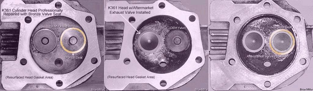
 Professionally replace loose and/or broken OEM valve seat with
a new high quality aftermarket hardened steel seat insert. $200.00 each
for labor and new seat, plus return shipping & handing.
Professionally replace loose and/or broken OEM valve seat with
a new high quality aftermarket hardened steel seat insert. $200.00 each
for labor and new seat, plus return shipping & handing.
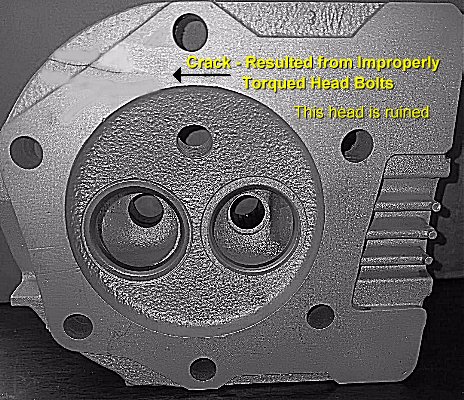
 Kohler Engine Model K361 (OHV 18hp) Cylinder Head Assembly.
Professionally rebuilt and fully assembled. No cracks. Cooling fins, spark
plug threads and bolt hole threads are all in good condition. Valve
seats and/or valve guides reground, repaired or replaced, where applicable.
Includes valves, springs, rotators, stabilizers and keepers. Cleaned and
resurfaced on a wide, flat
Kohler Engine Model K361 (OHV 18hp) Cylinder Head Assembly.
Professionally rebuilt and fully assembled. No cracks. Cooling fins, spark
plug threads and bolt hole threads are all in good condition. Valve
seats and/or valve guides reground, repaired or replaced, where applicable.
Includes valves, springs, rotators, stabilizers and keepers. Cleaned and
resurfaced on a wide, flat
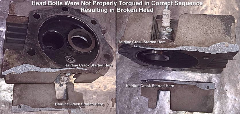


 Professional Repair or Rebuild Service for Kohler K-series
engine models K141, K160/K161, K181 and Magnum M8 cast iron block flathead
engine to OEM factory specifications at governed 3,600 RPM for general lawn
and garden use, snow removal or mild competition pulling. Only high quality
machine work is performed and replacement parts are installed! All baffle
shields (sheet metal) will need to be removed before bringing or shipping
engine to A-1 Miller's.
Professional Repair or Rebuild Service for Kohler K-series
engine models K141, K160/K161, K181 and Magnum M8 cast iron block flathead
engine to OEM factory specifications at governed 3,600 RPM for general lawn
and garden use, snow removal or mild competition pulling. Only high quality
machine work is performed and replacement parts are installed! All baffle
shields (sheet metal) will need to be removed before bringing or shipping
engine to A-1 Miller's. 
 Professional Rebuild Service
for Kohler engine model K361 OHV for general lawn and garden use, snow removal
or mild competition pulling. Only high quality machine work is performed
and replacement parts are installed! All baffle shields (sheet metal) will
need to be removed before bringing or shipping engine to A-1 Miller's.
Professional Rebuild Service
for Kohler engine model K361 OHV for general lawn and garden use, snow removal
or mild competition pulling. Only high quality machine work is performed
and replacement parts are installed! All baffle shields (sheet metal) will
need to be removed before bringing or shipping engine to A-1 Miller's.
 Do
not use a cardboard box alone and/or spray foam inside a cardboard box or
wooden crate to secure the engine! Spray foam bonds the box or crate together
and the box or crate might get destroyed when uncrating the engine. Crate
the engine well using Phillips head screws only and brace the engine with
wood so the engine and any parts included won't get damaged or lost in
shipping.
Do
not use a cardboard box alone and/or spray foam inside a cardboard box or
wooden crate to secure the engine! Spray foam bonds the box or crate together
and the box or crate might get destroyed when uncrating the engine. Crate
the engine well using Phillips head screws only and brace the engine with
wood so the engine and any parts included won't get damaged or lost in
shipping.