

 Miscellaneous Small Engine Repairs
and Garden Tractor Pulling Tips & Tricks
Miscellaneous Small Engine Repairs
and Garden Tractor Pulling Tips & Tricks(Information that don't fit in any other category.)
Miscellaneous Small Engine Repairs
and Garden Tractor Pulling Tips & TricksOptimized for 1024 x 768 screen resolution. To search for a word or phrase in any of my web sites, press CTRL and F simultaneously to open the Find dialog box in your web browser. Although every effort has been taken to check the accuracy of information contained herein, I cannot assume responsibility for errors. Scroll down this website or click the links below...
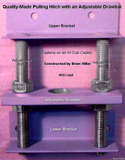
Using a Quality-Made Pulling Hitch with an Adjustable Drawbar on a Competition Cub Cadet Garden Pulling Tractor or Small Wheel Mini-Rod [Top of Page] (Updated 9/25/21 with more clarified information.)
 First
of all, when a pulling association's or club's sanctioning rules state that
"the tractor shall have no more than a 13" hitch height", this wording is
not accurate! It should read: "The tractor shall have no more than a 13"
drawbar/hitch
height." The
"drawbar" is a separate part that's supported by the framework
on the rear of the tractor. But if the drawbar is non-adjustable and is fastened,
welded to or part of the tractor/vehicle frame, then it's called the hitch,
as in
receiver hitch, to tow a trailer.
First
of all, when a pulling association's or club's sanctioning rules state that
"the tractor shall have no more than a 13" hitch height", this wording is
not accurate! It should read: "The tractor shall have no more than a 13"
drawbar/hitch
height." The
"drawbar" is a separate part that's supported by the framework
on the rear of the tractor. But if the drawbar is non-adjustable and is fastened,
welded to or part of the tractor/vehicle frame, then it's called the hitch,
as in
receiver hitch, to tow a trailer.
Anyway, if you can keep from doing so, don't use a non-adjustable, bolted-on-solid or welded-on hitch. It's not that the weld may break, but if you have to change the height height, or pull with another club that require a different hitch height, or if you were to change tire size, deflate/inflate tire pressure, change the diameter of the front tires, the hitch height can't be changed (lowered) for legality of the club's pulling rules. Therefore, with a fully adjustable drawbar, you can easily and quickly reset the drawbar height according to the club's rules. This will give your tractor a better advantage with the competition, and not be disqualified due to the hitch being too high (above 13" or whatever the club's rules allow).
To be truly competitive, always run the highest drawbar height your clubs' rules allow. But if the driver of a tractor is a large person, then lower the drawbar height to 12". Doing this will place more weight toward the front of the tractor so the driver will have better control while going down the track. And the further rearward the drawbar is located, the more weight must be placed on the front of the tractor. But if the drawbar is too close to the rear axle, it'll be hard to control the front end from rearing up and down uncontrollably at times. Therefore, the best position for the drawbar is 6-1/2" to 8" rearward from the center of the rear axle. This should allow the front of the tractor to rise gently (if the tractor is weighted correctly), which should give the driver full control of the tractor. This measurement applies to all makes and models of garden tractors and for all classes of pulling tractors, from a basic stock to a fully modified.
Information Concerning Strength and Safety of the Pulling Hitch with an Adjustable Drawbar Ê
 When certain pulling club's sanctioning rules state something like,
"the pulling point may not be more than 3/4 inches in depth," what they actually
mean is, on the drawbar, there must be no more (and no less, for strength)
than 3/4" of metal between inside rear of the hole and outside rearward edge
of the drawbar.
When certain pulling club's sanctioning rules state something like,
"the pulling point may not be more than 3/4 inches in depth," what they actually
mean is, on the drawbar, there must be no more (and no less, for strength)
than 3/4" of metal between inside rear of the hole and outside rearward edge
of the drawbar.
Also, for strength and safety, and because most rules don't bother mentioning this, the drawbar itself should be made of minimum 1/2" thickness steel, and not aluminum!
But the upper and lower angle brackets should be made of either minimum 1/8" thickness mild steel or minimum 1/4" thickness 6061 aluminum.
How to Construct a Professional Pulling Hitch with an Adjustable Drawbar Ê
 FYI:
This entire assembly is called the HITCH. The adjustable flat bar where the
hook goes is called the DRAWBAR.
FYI:
This entire assembly is called the HITCH. The adjustable flat bar where the
hook goes is called the DRAWBAR.
This type of garden tractor pulling hitch with an adjustable drawbar is the most common and strongest ever used. It's low-cost and looks nice, too. It's the design that most professional pullers use, plus it's NQS legal. It will adapt to virtually any garden tractor as long as two pieces of angled steel can be fastened on the rear.
Specifications are:
Identification and Torque Specifications for the Most
Commonly Used Grades of Bolts [Top of Page]
NOTE: Use Standard Torque Settings When Specific Values Are Not Specified.
(C) = Coarse thread, (F) = Fine thread
Hardness of Bolts
 |
No Lines = Grade 3
|
3 Lines = Grade 5
|
6 Lines = Grade 8
|
Stainless Steel or Special Alloy  |
| Bolt/Thread Size  |
Material: Low Carbon Steel. Tensile Strength: 85,000 P.S.I. (Low Strength) | Material: Medium Carbon Steel, Tempered. Tensile Strength: 120,000 P.S.I. (Medium Strength) | Material: Medium Carbon Alloy Steel, Quenched and Tempered. Tensile Strength: 150,000 P.S.I. (High Strength) | 18-8 [304] Stainless Steel |
1/4-20 (C) 1/4-28 (F) 5/16-18 (C) 5/16-24 (F) 3/8-16 (C) 3/8-24 (F) 7/16-14 (C) 7/16-20 (F) 1/2-13 (C) 1/2-20 (F) 9/16-12 (C) 9/16-18 (F) 5/8-11 (C) 5/8-18 (F) 3/4-10 (C) 3/4-16 (F) |
70 in. lb./ 6 ft. lb. 85 in. lb./ 7 ft. lb. 150 in. lb./13 ft. lb. 165 in. lb./14 ft. lb. 260 in. lb./22 ft. lb. 300 in. lb./25 ft. lb. 35 ft. lb. 45 ft. lb. 50 ft. lb. 70 ft. lb. 75 ft. lb. 100 ft. lb. 110 ft. lb. 140 ft. lb. 150 ft. lb. 200 ft. lb. |
115 in. lb./10 ft. lb. 140 in. lb./12 ft. lb. 250 in. lb./21 ft. lb. 270 in. lb./23 ft. lb. 35 ft. lb. 40 ft. lb. 55 ft. lb. 75 ft. lb. 80 ft. lb. 105 ft. lb. 125 ft. lb. 165 ft. lb. 180 ft. lb. 230 ft. lb. 245 ft. lb. 325 ft. lb. |
165 in. lb./14 ft. lb. 200 in. lb./17 ft. lb. 350 in. lb./29 ft. lb. 30 ft. lb. 50 ft. lb. 60 ft. lb. 80 ft. lb. 105 ft. lb. 115 ft. lb. 165 ft. lb. 175 ft. lb. 230 ft. lb. 260 ft. lb. 330 ft. lb. 350 ft. lb. 470 ft. lb. |
14 ft. lb. 17 ft. lb. 29 ft. lb. 35 ft. lb. 58 ft. lb. 69 ft. lb. 98 ft. lb. 110 ft. lb. 145 ft. lb. 160 ft. lb. 200 ft. lb. 220 ft. lb. 280 ft. lb. 310 ft. lb. 490 ft. lb. 530 ft. lb. |
How To Professionally Clean Out/Straighten Already Existing Threads or Cut New Threads [Top of Page]

 New threads in a drilled hole
(of the correct size) should ALWAYS be made with a (preferably new)
TAPER hand tap to prevent the possibility of breaking the
tap off in the hole! (This can be a nightmare, especially with an expensive
and/or non-replaceable part!) Taper taps are self-aligning, cut new threads
easily, much quicker and require less effort than plug taps. Then deeper
threads can be made with a PLUG or BOTTOM tap. (Care should still be taken
whenever cutting new threads, especially with smaller size taps.) Most hardware
stores do not stock taper (or bottom) hand taps. They keep mostly plug taps
in stock. Therefore, taper taps will need to be purchased online, such as
eBay or Amazon. And the only threading dies with tapered threads available
are for NPT pipe threads. These have a different pitch than any straight
bolt threads.
New threads in a drilled hole
(of the correct size) should ALWAYS be made with a (preferably new)
TAPER hand tap to prevent the possibility of breaking the
tap off in the hole! (This can be a nightmare, especially with an expensive
and/or non-replaceable part!) Taper taps are self-aligning, cut new threads
easily, much quicker and require less effort than plug taps. Then deeper
threads can be made with a PLUG or BOTTOM tap. (Care should still be taken
whenever cutting new threads, especially with smaller size taps.) Most hardware
stores do not stock taper (or bottom) hand taps. They keep mostly plug taps
in stock. Therefore, taper taps will need to be purchased online, such as
eBay or Amazon. And the only threading dies with tapered threads available
are for NPT pipe threads. These have a different pitch than any straight
bolt threads.
For best thread cutting results, use WD-40 when cutting new threads in aluminum, and when cutting new threads in cast iron or [mild] steel, use thread cutting oil, automatic transmission fluid (ATF) or power steering fluid (which is 10 weight hydraulic oil).
 about 1/2 turn to cut the threads, then
back it off counterclockwise
about 1/2 turn to cut the threads, then
back it off counterclockwise  about 1/4 turn.
This will loosen and somewhat dislodge the metal cuttings from the flutes
in the tap (open spaces between the cutting teeth). If the tap is difficult
to back off, DO NOT FORCE IT, especially a small tap! Instead, with the tap
in the hole, use (150± psi) compressed air to clear out the majority
of the metal cuttings from the hole (wear
safety glasses!), then GENTLY rotate the tap counterclockwise
until it rotates freely and comes out of
the hole. Again, use compressed air to clear out the metal cuttings from
the hole.
and 1/4 turn counterclockwise
until the new threads are cut all the way
in or through the hole.
about 1/4 turn.
This will loosen and somewhat dislodge the metal cuttings from the flutes
in the tap (open spaces between the cutting teeth). If the tap is difficult
to back off, DO NOT FORCE IT, especially a small tap! Instead, with the tap
in the hole, use (150± psi) compressed air to clear out the majority
of the metal cuttings from the hole (wear
safety glasses!), then GENTLY rotate the tap counterclockwise
until it rotates freely and comes out of
the hole. Again, use compressed air to clear out the metal cuttings from
the hole.
and 1/4 turn counterclockwise
until the new threads are cut all the way
in or through the hole.
Removing a Broken-Off Bolt from a Hole - As far as removing a broken-off bolt in an engine block or cylinder head for an exhaust flange is concerned, I have never had any luck with tapered spiral-fluted screw extractors. In my experience, all they do is thread itself deep into the drilled-out broken-off bolt and expand the bolt, making it harder, if impossible, to remove. Instead, what to do is grind flat any protruding metal of the broken-off bolt/stud, then precision center-drill into the broken-off bolt/stud with a short length drill bit or a centering bit (to prevent wobbling of the bit) as a pilot hole, then bore into the bolt/stud with the appropriate size drill bit, then re-thread the hole with a TAPER hand tap of the appropriate size, and then finish re-threading it with a PLUG tap.
Removing a Broken-Off Hand Tap from a Hole - A threading tap that has broken-off in an engine block or metal casting can be very difficult to remove. A HSS annular cutter could be used because these have a hollow center hole that can cut around the broken-off tap, Use an annular cutter with the same size center hole as the [broken-off] tap. Then the [bored] hole can be welded up, drilled and new threads made. Or Google: removing broken tap from hole, or have an experienced and reputable machine shop remove the broken-off tap. [Return To Previous Paragraph or Website]
Drill and Tap Chart for Inch Sizes
|
|
Drill and Tap Bit Chart for Inch, Special Inch and Metric Sizes
[Top of Page]
NOTE - There's three different type of drill bits - fraction, number and
letter. Actually, there's four, including metric. Use the one that's closest
to the size hole that needs to be drilled.
|
|
Drill and Tap Chart for National Pipe Tapered (NPT) Threads | NOTE - Recommended tap drill to use for 75% thread depth. [Top of Page]
| To Cut This Size Pipe Threads | Use This Size Drill Bit / Closest Fractional / Decimal Inches | Outside Diameter of Pipe |
| 1/16-27 NPT | D / 1/4" / .246" | 0.313" (5/16") |
| 1/8-27 NPT | R / 11/32" / .339" | 0.405" (13/32") |
| 1/4-18 NPT | 7/16" / .4375" | 0.540" (35/64") |
| 3/8-18 NPT | 37/64" / .5781" | 0.675" (43/64") |
| 1/2-14 NPT | 45/64" / .7031" | 0.840" (27/32") |
| 3/4-14 NPT | 59/64" / .9219" | 1.050" (1-3/64") |
| 1-11 1/2 NPT | 1-5/32" / 1.1562" | 1.315" (1-5/16") |
| 1-1/4-11 1/2 NPT | 1-1/2" / 1.500" | 1.660" (1-21/32") |
| 1-1/2-11 1/2 NPT | 1-47/64" / 1.7344" | 1.900" (1-57/64") |
| 2-11 1/2 NPT | 2-7/32" / 2.2188" | 2.375" (2-3/8") |
| Tap Size | Drill This Size Hole | Drill This Size Hole | Basic Major Millimeter Diameter | Basic Major Inch Diameter | Millimeters Per Thread |
| M1.6 x 0.35 | #55 | 1.25mm | 1.6mm | .063" | .35 |
| M2 x 0.4 | #52 | 1.6mm | 2mm | .0787" | .4 |
| M2.5 x 0.45 | #46 | 2.05mm | 2.5mm | .0984" | .45 |
| M3 x 0.5 | #39 | 2.5mm | 3mm | .1181" | .5 |
| M3.5 x 0.6 | #32 | 2.9mm | 3.5mm | .1378" | .6 |
| M4 x 0.7 | #30 | 3.3mm | 4mm | .1575" | .7 |
| M5 x 0.8 | #19 | 4.2mm | 5mm | .1969" | .8 |
| M6 x 1 | #8 | 5mm | 6mm | .2362" | 1 |
| M8 x 1.25 | H | 6.8mm | 8mm | .315" | 1.25 |
| M8 x 1 | J | 7mm | 8mm | .315" | 1 |
| M10 x 1.5 | R | 8.5mm | 10mm | .3937" | 1.5 |
| M10 x 1.25 | 11/32" | 8.8mm | 10mm | .3937" | 1.25 |
| M11 x 1.5 | 3/8" | 9.5mm | 11mm | .433" | 1.5 |
| M11 x 1.25 | U | 9.75mm | 11mm | .433" | 1.25 |
| M12 x 1.75 | 13/32" | 10.2mm | 12mm | .4724" | 1.75 |
| M12 x 1.25 | 27/64" | 10.8mm | 12mm | .4724" | 1.25 |
| M14 x 2 | 15/32" | 12mm | 14mm | .5512" | 2 |
| M14 x 1.5 | 1/2" | 12.5mm | 14mm | .5512" | 1.5 |
| M16 x 2 | 35/64" | 14mm | 16mm | .6299" | 2 |
| M16 x 1.5 | 37/64" | 14.5mm | 16mm | .6299" | 1.5 |
| M18 x 2.5 | 39/64" | 15.5mm | 18mm | .7087" | 2.5 |
| M18 x 1.5 | 21/32" | 16.5mm | 18mm | .7087" | 1.5 |
| M20 x 2.5 | 11/16" | 17.5mm | 20mm | .7874" | 2.5 |
| M20 x 1.5 | 47/64" | 18.5mm | 20mm | .7874" | 1.5 |
| M22 x 2.5 | 49/64" | 19.5mm | 22mm | .8661" | 2.5 |
| M22 x 1.5 | 13/16" | 20.5mm | 22mm | .8661" | 1.5 |
| M24 x 3 | 53/64" | 21mm | 24mm | .9449" | 3 |
| M24 x 2 | 7/8" | 22mm | 24mm | .9449" | 2 |
| M27 x 3 | 15/16" | 24mm | 27mm | 1.063" | 3 |
| M27 x 2 | 1" | 25mm | 27mm | 1.063" | 2 |
Decimals of | Decimals of | Decimals of MM an inch | MM an inch | MM an inch ------------------+----------------------+-------------------- .1 = .00394" | 1. = .03937" | 15. = .59055" .2 = .00787" | 2. = .07874" | 16. = .62992" .3 = .01181" | 3. = .11811" | 17. = .66929" .4 = .01575" | 4. = .15748" | 18. = .70866" .5 = .01968" | 5. = .19685" | 19. = .74803" .6 = .02362" | 6. = .23622" | 20. = .78740" .7 = .02756" | 7. = .27559" | 21. = .82677" .8 = .03149" | 8. = .32496" | 22. = .86614" .9 = .03543" | 9. = .35433" | 23. = .90551" 10. = .3937" | 12.7 = .500" | 24. = .94488" 11. = .43307" | 13. = .51181" | 25. = .98425" 12. = .47244" | 14. = .55118" | 25.4 = 1.000" |
Fraction/| | | Fraction/| | | Fraction/| | Number/ | Decimal | MM | Number/ | Decimal | MM | Number/ | Decimal | MM Letter | | | Letter | | | Letter | | ----------------------------+----------------------------+---------------------------- 1/64" = .0156" = .396 | #20 = .161" = 4.089 | T = .358" = 9.093 1/32" = .0312" = .795 | #19 = .166" = 4.216 | 23/64" = .3594" = 9.129 #60 = .040" = 1.016 | #18 = .1659" = 4.214 | U = .368" = 9.347 #59 = .041" = 1.041 | 11/64" = .1718" = 4.366 | 3/8" = .375" = 9.525 #58 = .042" = 1.067 | #17 = .173" = 4.394 | V = .377" = 9.576 #57 = .043" = 1.092 | #16 = .177" = 4.496 | W = .386" = 9.804 #56 = .043" = 1.092 | #15 = .180" = 4.572 | 25/64" = .3906" = 9.921 #55 = .0465" = 1.181 | #14 = .182" = 4.623 | X = .397" = 10.084 3/64" = .0468" = 1.191 | #13 = .185" = 4.699 | Y = .404" = 10.262 #55 = .052" = 1.321 | 3/16" = .1875" = 4.763 | 13/32" = .4063" = 10.320 #54 = .055" = 1.397 | #12 = .189" = 4.801 | Z = .413" = 10.49 #53 = .0595" = 1.511 | #11 = .191" = 4.851 | 27/64" = .4219" = 10.716 1/16" = .0625" = 1.588 | #10 = .1935" = 4.915 | 7/16" = .4375" = 11.113 #52 = .0635" = 1.613 | #9 = .196" = 4.978 | 29/64" = .4531" = 11.509 #51 = .067" = 1.701 | #8 = .199" = 5.055 | 15/32" = .4688" = 11.908 #50 = .070" = 1.778 | #7 = .201" = 5.105 | 31/64" = .4844" = 12.304 #49 = .073" = 1.854 | 13/64" = .2031" = 5.159 | 1/2" = .500" = 12.700 #48 = .076" = 1.930 | #6 = .204" = 5.182 | 33/64" = .5156" = 13.096 5/64" = .0781" = 1.984 | #5 = .2055" = 5.22 | 17/32" = .5312" = 13.495 #47 = .0785" = 1.994 | #4 = .209" = 5.309 | 35/64" = .5469" = 13.891 #46 = .081" = 2.06 | #3 = .213" = 5.41 | 9/16" = .5625" = 14.288 #45 = .082" = 2.083 | 7/32" = .2188" = 5.558 | 37/64" = .5781" = 14.684 #44 = .086" = 2.184 | #2 = .221" = 5.613 | 19/32" = .5938" = 15.083 #43 = .089" = 2.26 | #1 = .228" = 5.791 | 39/64" = .6094" = 15.479 #42 = .0935" = 2.375 | A = .234" = 5.943 | 5/8" = .625" = 15.875 3/32" = .0937" = 2.383 | 15/64" = .2344" = 5.954 | 41/64" = .6406" = 16.271 #41 = .096" = 2.438 | B = .238" = 6.045 | 21/32" = .6563" = 16.67 #40 = .098" = 2.489 | C = .242" = 6.147 | 43/64" = .6719" = 17.066 #39 = .0995" = 2.527 | D = .246" = 6.248 | 11/16" = .6875" = 17.463 #38 = .1015" = 2.578 | 1/4" = .250" = 6.35 | 45/64" = .7031" = 17.859 #37 = .104" = 2.642 | E = .250" = 6.35 | 23/32" = .7188" = 18.254 #36 = .1065 = 2.705 | F = .257" = 6.528 | 47/64" = .7344" = 18.654 7/64" = .1094" = 2.779 | G = .261" = 6.629 | 3/4" = .750" = 19.05 #35 = .110" = 2.794 | 17/64" = .2656" = 6.746 | 49/64" = .7656" = 19.446 #34 = .111" = 2.819 | H = .266" = 6.756 | 25/32" = .7813" = 19.845 #33 = .113" = 2.87 | I = .272" = 6.909 | 51/64" = .7969" = 20.241 #32 = .116" = 2.946 | J = .277" = 7.036 | 13/16" = .8125" = 20.638 #31 = .120" = 3.048 | K = .281" = 7.137 | 53/64" = .8282" = 21.034 1/8" = .125" = 3.175 | 9/32" = .2813" = 7.145 | 27/32" = .8438" = 21.433 #30 = .1285" = 3.195 | L = .290" = 7.366 | 55/64" = .8594" = 21.821 #29 = .136" = 3.454 | M = .295" = 7.493 | 7/8" = .875" = 22.225 #28 = .1405" = 3.569 | 19/64" = .2969" = 7.541 | 57/64" = .8906" = 22.621 9/64" = .1406" = 3.571 | N = .302" = 7.671 | 29/32" = .9063" = 23.020 #27 = .144" = 3.658 | 5/16" = .3125" = 7.938 | 59/64" = .9219" = 23.416 #26 = .147" = 3.734 | O = .316" = 8.026 | 15/16" = .9375" = 23.813 #25 = .1495" = 3.797 | P = .323" = 8.204 | 61/64" = .9532" = 24.209 #24 = .152" = 3.861 | 21/64" = .3281" = 8.334 | 31/32" = .9688" = 24.608 #23 = .154" = 3.912 | Q = .332" = 8.433 | 63/64" = .9844" = 25.004 5/32" = .1563" = 3.970 | R = .339" = 8.611 | 1" = 1.000" = 25.400 #22 = .157" = 3.988 | 11/32" = .3438" = 8.733 | #21 = .159" = 4.039 | S = .348" = 8.839 | |
| Thread Size | Maximum Diameter of Threads | Closest Drill Bit Size |
| 2-56 UNC | .086" | #44 / 3/32" / 3mm |
| 3-48 UNC | .099" | #39 / 7/64" / 3mm |
| 4-40 UNC | .112" | #33 or #34 / 3mm |
| 5-40 UNC | .125" | 1/8" / 4mm |
| 6-32 UNC | .138" | 9/64" / 4mm |
| 8-32 UNC | .164" | 11/64" / 5mm |
| 10-24 UNC | .190" | 3/16" / 5mm |
| 10-32 UNF | .190" | 3/16" / 5mm |
| 12-24 UNC | .216" | 7/32" / 6mm |
Useful Conversion Charts, etc. [Top of Page]
| Gauge | Standard Steel | Galvanized Steel | Aluminum | Gauge | Standard Steel | Galvanized Steel | Aluminum | |
| 3 | 0.2391" | - | 0.2294" | 20 | 0.0359" | 0.0396" | 0.0320" | |
| 4 | 0.2242" | - | 0.2043" | 21 | 0.0329" | 0.0366" | 0.0285" | |
| 5 | 0.2092" | - | 0.1819" | 22 | 0.0299" | 0.0336" | 0.0253" | |
| 6 | 0.1943" | - | 0.1620" | 23 | 0.0269" | 0.0306" | 0.0226" | |
| 7 | 0.1793" | - | 0.1443" | 24 | 0.0239" | 0.0276" | 0.0201" | |
| 8 | 0.1644" | - | 0.1285" | 25 | 0.0209" | 0.0247" | 0.0179" | |
| 9 | 0.1495" | 0.1532" | 0.1144" | 26 | 0.0179" | 0.0217" | 0.0159" | |
| 10 | 0.1345" | 0.1382" | 0.1019" | 27 | 0.0164" | 0.0202" | 0.0142" | |
| 11 | 0.1196" | 0.1233" | 0.0907" | 28 | 0.0149" | 0.0187" | 0.0126" | |
| 12 | 0.1046" | 0.1084" | 0.0808" | 29 | 0.0135" | 0.0172" | 0.0113" | |
| 13 | 0.0897" | 0.0934" | 0.0720" | 30 | 0.0120" | 0.0157" | 0.0100" | |
| 14 | 0.0747" | 0.0785" | 0.0641" | 31 | 0.0105" | 0.0142" | 0.0089" | |
| 15 | 0.0673" | 0.0710" | 0.0571" | 32 | 0.0097" | 0.0134" | 0.0080" | |
| 16 | 0.0598" | 0.0635" | 0.0508" | 33 | 0.0090" | - | 0.0071" | |
| 17 | 0.0538" | 0.0575" | 0.0453" | 34 | 0.0082" | - | 0.0063" | |
| 18 | 0.0478" | 0.0516" | 0.0403" | 35 | 0.0075" | - | 0.0056" | |
| 19 | 0.0418" | 0.0456" | 0.0359" | 36 | 0.0067" | - | - |
A-1 Miller's Performance Enterprises Professional Automotive Services Available in Central Missouri!
Professional Automotive Air Conditioning (A/C) Services
Professional Old School Automotive Services
Competitively Built and Nice-Appearing Small Wheel (26-12.00x12) Mini Rod Pulling Tractors
Detailed Illustrated Plans on How to Construct a Professional Garden Tractor Pulling Sleds
Quality-Built and Nice-Appearing Garden Tractor & Mini Rod Self-Propelled Tractor Pulling Sleds (Weight Transfer Machines) For Sale
Complete Narrowed Automotive Rear End/Differential for Use in Garden Tractor Pulling Sled
 To
place an order, send your item(s) for repairing, and/or for customer service
assistance, and FREE honest and accurate technical support, please contact:
A-1 Miller's Performance Enterprises, 12091 N Route B, Hallsville, MO (Missouri)
65255-9604 USA. Please call in your order or send an email with a list parts
you need and your contact information.
To
place an order, send your item(s) for repairing, and/or for customer service
assistance, and FREE honest and accurate technical support, please contact:
A-1 Miller's Performance Enterprises, 12091 N Route B, Hallsville, MO (Missouri)
65255-9604 USA. Please call in your order or send an email with a list parts
you need and your contact information.
 Phone: 1-573-881-7229 (cell;
call, text or leave voicemail) or use
Whatsapp. Please call
Monday-Friday, 9am to 5pm, Central time zone, except holidays. If no answer,
please try again later.
Phone: 1-573-881-7229 (cell;
call, text or leave voicemail) or use
Whatsapp. Please call
Monday-Friday, 9am to 5pm, Central time zone, except holidays. If no answer,
please try again later.  E-mail:
pullingtractor@aol.com.
Payment Options. A-1 Miller's shop is open
to the public Monday-Friday, 9am to 5pm, Central time zone, with an appointment
on weekends, except holidays. If you're the kind of person who don't trust
delivery/shipping companies (mis)handling your high-dollar and fragile
merchandise, you can make the long drive to A-1 Miller's new shop (click
image to the right) to personally purchase parts, or drop off and/or pick
up your carburetor, clutch assembly, engine and/or parts, etc., for repairing
and/or rebuilding. Or visit the address of our (old) shop mentioned above
to drop off your engine, transmission, transaxle, garden tractor, small motorized
vehicle, etc. We also custom build pulling tractors and other small vehicles.
Please contact me before coming so I'll be at my shop waiting for your arrival.
When you visit our shop, you will be dealing directly with the owner for
the best customer service. "The road to a [trusted] friend's house (or
shop) is never long." Don't sacrifice quality workmanship for distance.
Photos
of our new building/shop are posted here!
12091 N Route B, Hallsville, MO - Google Maps.
[Return To Previous Paragraph, Section
or Website]
E-mail:
pullingtractor@aol.com.
Payment Options. A-1 Miller's shop is open
to the public Monday-Friday, 9am to 5pm, Central time zone, with an appointment
on weekends, except holidays. If you're the kind of person who don't trust
delivery/shipping companies (mis)handling your high-dollar and fragile
merchandise, you can make the long drive to A-1 Miller's new shop (click
image to the right) to personally purchase parts, or drop off and/or pick
up your carburetor, clutch assembly, engine and/or parts, etc., for repairing
and/or rebuilding. Or visit the address of our (old) shop mentioned above
to drop off your engine, transmission, transaxle, garden tractor, small motorized
vehicle, etc. We also custom build pulling tractors and other small vehicles.
Please contact me before coming so I'll be at my shop waiting for your arrival.
When you visit our shop, you will be dealing directly with the owner for
the best customer service. "The road to a [trusted] friend's house (or
shop) is never long." Don't sacrifice quality workmanship for distance.
Photos
of our new building/shop are posted here!
12091 N Route B, Hallsville, MO - Google Maps.
[Return To Previous Paragraph, Section
or Website]
Payment Options, and We Ship to Canada and
Worldwide 
Item(s) in a package or cushioned envelope weighing less than 1 lb. is sent
by US Postal Service Airmail Letter Post for a 4-7 days delivery. Packaged
item(s) weighing over 1 lb. and up to 66 lb. is sent by US Postal Service
Airmail Parcel Post for a 4-10 days delivery. I cannot use the US Postal
Services' Flat Rate Priority Mail envelopes and boxes to ship outside U.S.
territories. Item(s) weighing over 67 lbs. or more is sent by FedEx Ground
or equivalent services. We try to keep our shipping cost to customers within
reason. Therefore, we don't ship our products in a fancy-looking package
with our company name and/or logo on it because most customers will just
toss it in the trash after they remove the contents. And being there is no
USPS tracking number outside the US, all I can do is make sure I write your
address correctly on the customs form and on your package.
My websites are not set up to process orders and accept payments. Therefore, to place an order with me, please call either number above or send an email with a list of parts you need, with your name, complete and correct postal mailing address and phone number. For payment options, I accept cash (in person), USPS Postal Money Orders, cashier's checks, business checks, MasterCard, VISA, Discover, American Express (please add 2.5% to the total amount for the credit/debit card processor's surcharge). If paying with a credit/debit card, please call me at either number above. Or to make a payment to me through PayPal, please click this link: https://www.paypal.com. Or use Cash App (username: pullingtractor) or Venmo (username: Pullingtractor) to make a payment to me. And be sure to mention a description of what the payment is for with your full name, postal address, phone number and email address. I also accept payments through Western Union Money Transfer or MoneyGram Money Transfers. If sending a money order or cashier's check, please include a note in the envelope with your name, complete mailing address, phone number, email address and a description of what the payment is for. I'll make a note of your order when I have all your information, and I may have to order some of the parts on your list, which should take a few days to come in, but I will send everything to you as soon as I have the parts in stock after I receive your payment.


Return To Previous Website | Top of Page
Copyright © 1996-Present. This website created, designed and maintained by A-1 Miller's Performance Enterprises


