
 Information About Small Engine Porting, Valves, Springs, Lifters
and Camshafts
Information About Small Engine Porting, Valves, Springs, Lifters
and Camshafts
Information About Small Engine Porting, Valves, Springs, Lifters
and Camshafts
Information About Small Engine Porting, Valves, Springs, Lifters
and Camshafts
Inspiring Small Engine, Lawn & Garden, and Garden Pulling Tractor Enthusiasts Since 1996. Where Science and Common Sense Come Together for Safety and Improved Engine/Tractor Performance | A-1 Miller's Performance Enterprises - Parts & Services Webstore
Nowadays, prices are subject to change without notice. Click
Refresh to see any
changes or updates. Optimized for 1152 x 864 computer screen resolution.
To search for a word or phrase in any of my websites, press the CTRL
 and F
and F  keys on
your keyboard simultaneously to open the Find or Search dialog box in your
web browser. Scroll down the website or click the links below.
keys on
your keyboard simultaneously to open the Find or Search dialog box in your
web browser. Scroll down the website or click the links below.
Information About the Valves in Four Stroke Engines -
FYI - I receive many phone calls and emails from people who tell A-1 Miller's that when they have a problem with how poorly their engine runs. They say they cleaned and rebuilt the carburetor, but the engine would not run well, or still run the same. So they remove the carburetor, cleaned it again, and the engine still acts the same. So they check the carburetor again! They say they checked it over and cleaned it multiple times. Then they move on to the ignition system, but it checks out okay, too. Anyway, I tell them if you checked and cleaned the carburetor that many times and everything looked okay with it, then the problem obviously ISN'T in the carburetor or with the ignition! There are other things that help make an engine run, such as the valves. I tell them to check the valve clearances, severely leaking valves, or a professional valve job (this is when the valve faces and seats are recut or reground to specs or new valve(s) are installed and the valve clearances are set to factory specs so the engine will restore full compression) may need to be performed. Performing a valve job will restore full compression, which will allow the engine to start quicker, idle smoothly, rev up with no hesitation, produce lots of power, and run for a long time without stalling or dying (when the ignition timing and carburetor adjustments are set correctly, too). Also, check for a loose valve seat (Kohler 18hp OHV). The valves are the hardest working parts in any 4-cycle engine. They need attention, too. So many people are ignorant or know nothing about the valves, how they work or their purpose. So before disassembling, inspecting, cleaning and perhaps rebuilding the carburetor, you might want to check the valve clearances to see if they don't need to be reset to factory specs. Because I found that sometimes carburetor problems are valve-related.
If a 4-cycle engine cranks over too easy and is hard to start, and when it (or if) does start, it loses power and/or dies for no apparent reason after running for a while, then chances are the problem is in the valves. Valve faces and/or seats become worn (grooved) after many hours of use, and this lessons the clearance between the valve stems and lifters or rocker arms. Metal contracts (shrinks) when cold and expands (swells) when hot. Knowing this, when an engine reaches operating temperature, the valves get hot and swell, especially the exhaust valve, and this lessons the clearance between the stems and lifters or rocker arms. The hotter a valve gets, the less clearance it will have. When there's inadequate clearance, the valves will not be able to fully close or stay closed long enough to seal in sufficient amount of compression within the combustion chamber, the engine will lose compression, making the engine suddenly die, and hard to start and when it does start, it won't produce much power. Due to fuel vapors escaping the combustion chamber, sometimes gas will blow out the carburetor when the engine is accelerated, too. And when the engine dies for no apparent reason, it'll be almost impossible to restart when hot. To fix this, a professional valve job will need to be performed. What causes valve faces and/or seats to wear is lack of an air filter element (which will wear parts within the entire combustion chamber under dusty conditions), a dirty air filter, a defective air filter, or an air filter that has not been changed in a long time. Air filtration is very important with any engine. Especially under extreme dusty conditions. And just like fuel filters, air filters can only filter out dust particles so small. The smallest pieces of dust penetrates the microscopic holes in the filter material, and wears parts within the combustion chamber.

 In most cases, the valve face will more than the seat because
the moving part always wears more than the stationary part. And main thing
that cause valve face wear on the exhaust valve is a worn
valve guide, which cause the face to scrape against
the seat upon closing, and/or carbon deposits being lodged between the valve
face and seat. The intake valve face wears from guide wear also and/or either
lack of an air filter or not frequently using a new air filter. Clogged filters
can cause microscopic dust particles to penetrate the filter and enter the
combustion chamber. Due to microscopic dust particles that pass through the
air filter (which is unpreventable), this cause the valve face and seat to
wear against each other, and as they wear, the gap closes up between the
valve stem and lifter (tappet). This is why it's necessary to check and/or
adjust the valves every 500 hours of
engine run time. This is also why
it's important to use a quality-made air filter, and change it regularly,
especially under dusty conditions. Only the valves in engines with solid
lifters (tappets) need periodic adjusting. The valves in engines with hydraulic
lifters don't need adjusting because the oil in the lifters compensate for
the valve face and seat wear. An intake valve with a worn (grooved) 45º
face angle can be reground to a 30º angle, and of course the seat will
also need to be reground to a 31º to match the valve face.
In most cases, the valve face will more than the seat because
the moving part always wears more than the stationary part. And main thing
that cause valve face wear on the exhaust valve is a worn
valve guide, which cause the face to scrape against
the seat upon closing, and/or carbon deposits being lodged between the valve
face and seat. The intake valve face wears from guide wear also and/or either
lack of an air filter or not frequently using a new air filter. Clogged filters
can cause microscopic dust particles to penetrate the filter and enter the
combustion chamber. Due to microscopic dust particles that pass through the
air filter (which is unpreventable), this cause the valve face and seat to
wear against each other, and as they wear, the gap closes up between the
valve stem and lifter (tappet). This is why it's necessary to check and/or
adjust the valves every 500 hours of
engine run time. This is also why
it's important to use a quality-made air filter, and change it regularly,
especially under dusty conditions. Only the valves in engines with solid
lifters (tappets) need periodic adjusting. The valves in engines with hydraulic
lifters don't need adjusting because the oil in the lifters compensate for
the valve face and seat wear. An intake valve with a worn (grooved) 45º
face angle can be reground to a 30º angle, and of course the seat will
also need to be reground to a 31º to match the valve face.
The valves, especially the exhaust valve, is/are the hardest working part(s) of the engine. The valve face(s) can wear more than the piston rings. This is one thing so many mechanics overlook, yet so simple to fix.
How to Test for Leaking or Burnt Valves - [Top of Page]
 The appearance of used
valves in an engine are like women,
you can't always go by looks. In other words, the appearance of valves in
an engine won't tell you if they're sealing in compression 100% or not. To
test for leaking valves on virtually any 4-cycle flathead engine, first of
all, both valve clearances should be checked and adjusted to specs, if needed,
before performing this test. Now with the carburetor, muffler or exhaust
pipe and [flathead] cylinder head removed, and with the piston positioned
exactly at TDC on the compression stroke (this is when both valves are fully
closed), apply
Liquid Wrench (spray) or
WD-40 around each valve and with a rag/shop towel wrapped
around an
air blow gun nozzle with the rag/shop towel snug against
the port to seal in the air pressure so maximum pressure will be applied
to the valves, apply 150± PSI compressed air through the exhaust and
intake ports. To perform this same test on an over head valve (OHV) engine,
the cylinder head will need to be removed and [lightly] clamped in a bench
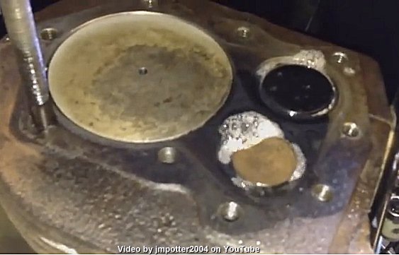
vise. Anyway, if multiple bubbles form (slight leakage) and/or if the liquid
gets "blown out" around the valves (severe leakage) when applying the air
pressure, this means the valves are leaking or burnt and a professional valve
job is required. Performing a valve job will restore full compression, which
will allow the engine to start quicker, idle smoothly, rev up with no hesitation,
produce lots of power, and run for a long time without stalling or dying
(when the ignition timing and carburetor adjustments are set correctly, too).
Do not use soapy water to perform this test because the water content will
cause the cast iron to rust if not immediately cleaned off and thoroughly
dried. The "bubbles" part of this test won't be accurate with freshly reground
valves and seats (fresh valve job) because the valves haven't worn into the
seats yet to form a perfect seal. This is known as valve wear-in or more
commonly as engine break-in. Click the photo to the right ->
è to watch how this test is performed
on
YouTube.
By the way - The video shows both valves fully closed with the piston positioned
at TDC on the compression stroke. And if you're wondering, the Automatic
Compression Release (ACR) only works with the exhaust valve. It doesn't hold
the exhaust valve open when the piston is at top dead center (TDC) on the
compression stroke. It only works when the piston is traveling about halfway
up in the cylinder just before it reaches top dead center (BTDC) on the
compression stroke.
The appearance of used
valves in an engine are like women,
you can't always go by looks. In other words, the appearance of valves in
an engine won't tell you if they're sealing in compression 100% or not. To
test for leaking valves on virtually any 4-cycle flathead engine, first of
all, both valve clearances should be checked and adjusted to specs, if needed,
before performing this test. Now with the carburetor, muffler or exhaust
pipe and [flathead] cylinder head removed, and with the piston positioned
exactly at TDC on the compression stroke (this is when both valves are fully
closed), apply
Liquid Wrench (spray) or
WD-40 around each valve and with a rag/shop towel wrapped
around an
air blow gun nozzle with the rag/shop towel snug against
the port to seal in the air pressure so maximum pressure will be applied
to the valves, apply 150± PSI compressed air through the exhaust and
intake ports. To perform this same test on an over head valve (OHV) engine,
the cylinder head will need to be removed and [lightly] clamped in a bench
vise. Anyway, if multiple bubbles form (slight leakage) and/or if the liquid
gets "blown out" around the valves (severe leakage) when applying the air
pressure, this means the valves are leaking or burnt and a professional valve
job is required. Performing a valve job will restore full compression, which
will allow the engine to start quicker, idle smoothly, rev up with no hesitation,
produce lots of power, and run for a long time without stalling or dying
(when the ignition timing and carburetor adjustments are set correctly, too).
Do not use soapy water to perform this test because the water content will
cause the cast iron to rust if not immediately cleaned off and thoroughly
dried. The "bubbles" part of this test won't be accurate with freshly reground
valves and seats (fresh valve job) because the valves haven't worn into the
seats yet to form a perfect seal. This is known as valve wear-in or more
commonly as engine break-in. Click the photo to the right ->
è to watch how this test is performed
on
YouTube.
By the way - The video shows both valves fully closed with the piston positioned
at TDC on the compression stroke. And if you're wondering, the Automatic
Compression Release (ACR) only works with the exhaust valve. It doesn't hold
the exhaust valve open when the piston is at top dead center (TDC) on the
compression stroke. It only works when the piston is traveling about halfway
up in the cylinder just before it reaches top dead center (BTDC) on the
compression stroke.
Performing a Compression Leak Down Test with a Leak Down Tester -
 With the piston is positioned
exactly at Top Dead Center (TDC) on the compression stroke, the automatic
compression release (ACR) mechanism allows the exhaust valve to fully close,
then a leak down test can be performed. The ACR effects a compression test
when performed with a
compression tester, but not a leak down test (as long as
the piston is at TDC on the compression stroke). 0º TDC is when the
piston is at its very top in the cylinder with both valves fully closed.
It is also when the T mark on the flywheel is aligned with
the raised boss on the bearing plate, and The alignment can be seen with
a flashlight through the sight hole in the bearing plate. But the best way
to determine if an engine needs to
be rebuilt is to remove the cylinder head & look at the edge of the piston.
If the carbon is washed away, this means the rings & piston are worn
and the engine needs rebuilding.
With the piston is positioned
exactly at Top Dead Center (TDC) on the compression stroke, the automatic
compression release (ACR) mechanism allows the exhaust valve to fully close,
then a leak down test can be performed. The ACR effects a compression test
when performed with a
compression tester, but not a leak down test (as long as
the piston is at TDC on the compression stroke). 0º TDC is when the
piston is at its very top in the cylinder with both valves fully closed.
It is also when the T mark on the flywheel is aligned with
the raised boss on the bearing plate, and The alignment can be seen with
a flashlight through the sight hole in the bearing plate. But the best way
to determine if an engine needs to
be rebuilt is to remove the cylinder head & look at the edge of the piston.
If the carbon is washed away, this means the rings & piston are worn
and the engine needs rebuilding.
FYI - If you have a Kohler 7-16hp ACR camshaft that was broke in two by a thrown connecting rod, save the spring off of it. It can be used on another good cam that may not have one. Or if your ACR spring places little or weak pressure against the flyweights/levers, it can be re-bent or reshape to its original condition to place sufficient tension against the flyweights/levers.

 Along with a dirty air filter, or no air filter, a worn throttle shaft
will also cause excessive wear to the valve faces and seats, especially the
intake valve and seat. These are the #1 cause of most engines wearing out
prematurely. The air filter situation is obvious, but if a carburetor has
a worn throttle shaft, this will create a vacuum leak and the engine will
idle poorly, if at all at times. Not to mention the engine will also draw
in dirty air, causing wear on the valve faces/seats and piston rings, and
engine will burn oil. More than .010" of play is considered too much for
throttle shaft wear. Plus, at operating running speeds (3,600 RPM), the extra
air will cause the engine to run lean on fuel, which will overheat the combustion
chamber and cause the cylinder head to warp (blow a head gasket) and the
piston and rings to wear prematurely, eventually resulting in severe engine
wear and excessive oil burning. Along with regular maintenance, repair of
a worn throttle shaft is required to help an engine last a long time. The
most accurate way to check for amount of wear is with a
dial indicator.
Along with a dirty air filter, or no air filter, a worn throttle shaft
will also cause excessive wear to the valve faces and seats, especially the
intake valve and seat. These are the #1 cause of most engines wearing out
prematurely. The air filter situation is obvious, but if a carburetor has
a worn throttle shaft, this will create a vacuum leak and the engine will
idle poorly, if at all at times. Not to mention the engine will also draw
in dirty air, causing wear on the valve faces/seats and piston rings, and
engine will burn oil. More than .010" of play is considered too much for
throttle shaft wear. Plus, at operating running speeds (3,600 RPM), the extra
air will cause the engine to run lean on fuel, which will overheat the combustion
chamber and cause the cylinder head to warp (blow a head gasket) and the
piston and rings to wear prematurely, eventually resulting in severe engine
wear and excessive oil burning. Along with regular maintenance, repair of
a worn throttle shaft is required to help an engine last a long time. The
most accurate way to check for amount of wear is with a
dial indicator.
The Difference Between an Amature Valve Job and Performing a Professional Valve Job -
 First of all, performing a
professional valve job is when the valve faces and seats are recut or reground
to specs or new valve(s) are installed and the valve clearances are set to
factory specs so the engine will restore full compression, which will allow
the engine to start quicker, idle smoothly, rev up with no hesitation, produce
lots of power, and run for a long time without stalling or dying (when the
ignition timing and carburetor adjustments are set correctly, too). Therefore,
when some people rebuild an engine,
they will not perform a professional valve job! Sometimes they pay no attention
whatsoever to the valves. But when they do, they just clean the valves and
lap them in with
valve grinding compound (which can be purchased online
and at virtually any auto parts store). They think this is a how valves and
seats are reground and how a valve job is performed. And many people won't
even set the valve clearances afterwards! Valves and seats become warped
(slightly bent or moved out of alignment) due to heating of cast iron (or
aluminum) the first time the engine was ran. This is how all flathead engines
and OHV cylinder heads "take shape" or bend and twist a few thousandths of
an inch. The valve faces need to be reground in a valve grinding machine
so they can be "trued-up" again, and the seats need to be recut or reground
with specialized valve seat tooling so the seat will be in perfect alignment
with the centerline of the valve guide again.
First of all, performing a
professional valve job is when the valve faces and seats are recut or reground
to specs or new valve(s) are installed and the valve clearances are set to
factory specs so the engine will restore full compression, which will allow
the engine to start quicker, idle smoothly, rev up with no hesitation, produce
lots of power, and run for a long time without stalling or dying (when the
ignition timing and carburetor adjustments are set correctly, too). Therefore,
when some people rebuild an engine,
they will not perform a professional valve job! Sometimes they pay no attention
whatsoever to the valves. But when they do, they just clean the valves and
lap them in with
valve grinding compound (which can be purchased online
and at virtually any auto parts store). They think this is a how valves and
seats are reground and how a valve job is performed. And many people won't
even set the valve clearances afterwards! Valves and seats become warped
(slightly bent or moved out of alignment) due to heating of cast iron (or
aluminum) the first time the engine was ran. This is how all flathead engines
and OHV cylinder heads "take shape" or bend and twist a few thousandths of
an inch. The valve faces need to be reground in a valve grinding machine
so they can be "trued-up" again, and the seats need to be recut or reground
with specialized valve seat tooling so the seat will be in perfect alignment
with the centerline of the valve guide again.
Just cleaning the valves, setting the clearances to specs and "lapping them in" is not performing a professional valve job. If the engine lacks power or dies frequently, then chances are, the valves (and seats) aren't burnt, they're just warped from normal engine heat. This happens on seasoned flathead engine blocks and OHV (Over Head Valve) cylinder heads for the first time. And chances are, the valve faces are worn too, due to normal wear against the seats. This is what causes insufficient or lesser valve clearance. BUT, just lapping the valves in with the seats without first regrinding either will show if the valve face is making contact with the seat 360º or not. If the valve head is warped, slightly bent or burnt, part of the valve lapping compound will NOT make 360º contact with the face, but will likely with the seat. Because seats rarely get severely "get out of alignment" with the valve.
How to Perform a Professional Valve Job -
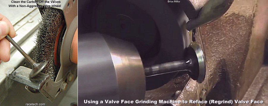
 Dotted lines or skip marks
on valve faces after lapping-in means the stone in the valve grinding machine
needs to be trued-up. The stone must be periodically trued-up, because due
to a lot of use, it will wear unevenly, resulting in erratic or unsmooth
valve face grinding.
Dotted lines or skip marks
on valve faces after lapping-in means the stone in the valve grinding machine
needs to be trued-up. The stone must be periodically trued-up, because due
to a lot of use, it will wear unevenly, resulting in erratic or unsmooth
valve face grinding.
FYI - Valve seat inserts in Kohler flathead engines, with the exception of the K361 OHV engine, are made of extremely hardened steel and rarely wear, get damaged, crack or loosen. In fact, I have never replaced a valve seat in any of the 100's of Kohler flathead engines that I've professionally rebuilt over the years. All I do to valve seats is recut or regrind the 46º [intake or exhaust factory angle] or 31º angle [intake only; to increase airflow] to put them back in perfect alignment with the centerline of the valve guide to ensure proper 360º valve sealing. And regardless to what some amateur or inexperienced engine rebuilders believe, valve seats are always recut or reground while in the block (or OHV engine). They are never removed to be recut or reground.
Before regrinding the valve faces and seats, the valve guides should be measured for excessive wear and replaced or repaired with a thin-wall bronze sleeve/liner if necessary, then the valve seats can be recut or reground with valve cutting or grinding equipment to be perpendicular with the centerline of the valve guides. This is important because the cast iron or aluminum engine block (flathead) or OHV (Over Head Valve) cylinder head can "move" or "bend and twist" just a few thousandths of an inch when it got hot for the very first time under normal operating conditions. This is called metal taking shape. Anyway, this "bending and twisting" of the metal can unseat the valve(s), and cause the engine to loose power, not idle well, and make carburetor adjustments difficult, especially at idle. I've seen this happen many times when individuals would rebuild their own engines. Valve lapping only places a rough surface on the valve face(s) and seat(s) so they'll wear-in with each other to produce a perfect seal, but the seats and faces may not be perfectly in-line with the valve stem, which can cause leaking of compression, resulting in lose of engine power. If one don't have their own valve grinder, most automotive machine shops will regrind valve faces for a few bucks. They can also regrind or recut the seats in a flathead engine block or an OHV cylinder head.
FYI - The alternative to installing new replacement OEM-type valve guide(s) is to have the old [worn] guide(s) reamed for installation of thin-wall bronze sleeves/liners (bushings), which can be installed by an experienced and reputable automotive machine shop. Thin-wall bronze valve guides are a low-cost and actually works better than replacing the OEM guide in most engines. Bronze lasts longer than cast iron guides because it is harder material and it retains more oil for better lubrication of the valve stem. Installing CLASSIC Bronze-Liners
The valve faces need to be lapped in enough to create a gray colored line that's the same width of the valve seat (1/16"-3/32" wide) midway in the valve face. Then thoroughly clean off the valve lapping compound from the valve and seat, and look to see if the valve lapping compound made contact 360º around the valve face and seat. Most valves will lap midway on the valve face. The outer and inner areas of the valve face should remain shiny from the regrinding process or from being new, and the whole area of the seat should look gray. If this is the case, then the valve should seal 100% when it wears into the seat.
Valve Head Margin -
 Most used valves can be reground and reused in an engine and
give good service for a long time if the face is not severely burnt, head
has a wide margin, and the stem is not bent. The minimum margin width for
Kohler valves is .030". If the margin is too thin, the head of the valve,
especially the exhaust valve due to extreme heat, could become concaved or
collapse in the seat. When this happens, the clearance between the lifter
and valve stem is lessened and the valve will not fully close, and the angles
of the seat valve face will not match, causing the valve to possibly leak
and/or burn. FYI - Regardless of what you've heard, running an engine
without a muffler or some kind of exhaust system will NOT cause the exhaust
valve to burn. This is an old mechanic's myth that got started many years
ago when poor quality metal was used in the manufacturing of exhaust valves.
Technology in
metallurgy and quality of exhaust valves have advanced
a lot in recent years.
Most used valves can be reground and reused in an engine and
give good service for a long time if the face is not severely burnt, head
has a wide margin, and the stem is not bent. The minimum margin width for
Kohler valves is .030". If the margin is too thin, the head of the valve,
especially the exhaust valve due to extreme heat, could become concaved or
collapse in the seat. When this happens, the clearance between the lifter
and valve stem is lessened and the valve will not fully close, and the angles
of the seat valve face will not match, causing the valve to possibly leak
and/or burn. FYI - Regardless of what you've heard, running an engine
without a muffler or some kind of exhaust system will NOT cause the exhaust
valve to burn. This is an old mechanic's myth that got started many years
ago when poor quality metal was used in the manufacturing of exhaust valves.
Technology in
metallurgy and quality of exhaust valves have advanced
a lot in recent years.
Regrinding the valve faces at a 30º or 45º angle places the valve head in perfect alignment (perpendicular) with the stem or "straightens them out" again so they'll be good as new. And regrinding or re-cutting the seats at a 31º or 46º angle ensures that the valve stems will be centered in the valve guides and the faces will seal 360º around. The reason for the 30º/31º or 45º/46º angles are so the valves and seats can wear into each other, producing a 30-½º or 45-½º angle for each, creating a perfect 100% seal. If each were reground at the same angle, carbon deposits would become lodged between them and eventually the valve face would burn. Anyway, after the valves and seats are reground, the valve clearances can be set at specs with the piston positioned exactly at top dead center on the compression stroke. Then lap them in so the faces will produce a wear pattern on the seats (the lapping process helps produce the perfect 30-½º or 45-½º angle for each). After the valves are matched perfectly with the seats after about 2 hours of normal engine operation, the engine should start quicker, produce more power and the valves should last the life of the engine.
If you want a factory stock lawn & garden or stock competition pulling engine with an intake valve that has a factory-ground 45º/46º intake valve and seat, for it to produce a few more ponies, regrind the intake valve face and seat at 30º and 31º, respectively. Doing this will allow slightly more air (and fuel) to enter the combustion chamber to create higher compression pressures. It will do absolutely no harm to the engine either. Briggs & Stratton have been doing this (plus other performance enhancements) to their flathead aluminum block engines since 1969, and it works great! Briggs even gave the cylinder head on their 3.5hp flathead lawn mower engines a specially designed combustion chamber that increases the air charge when the incoming air (and fuel) enters the combustion chamber, and scavenges the burnt gases more thoroughly when exiting the combustion chamber!
 As a matter
of fact, since 1969, ALL Briggs & Stratton flathead aluminum block engines
are built-to-the-max at 3,600 RPM at the factory to produce as power as possible,
but still last a long time. This does not lessen the longevity of the engine.
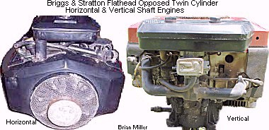
All B&S aluminum block single cylinder engines and the B&S flathead
opposed twin cylinder engines have a factory-installed performance-ground
camshaft with increased duration/overlap. This is why the opposed twin cylinder
engines produce a "lope, lope, lope" sound out the exhaust at slow idle.
This can't be heard with the single cylinder engines. There are very few-to-no
improvements or modifications that can be made to B&S engines so they
will produce more horsepower and torque at 3,600 RPM, with the exception
of the 5hp B&S flathead racing go-kart engines, which run at open RPM.
Why Kohler didn't follow B&S's method of building to the max engines,
I have no idea.
As a matter
of fact, since 1969, ALL Briggs & Stratton flathead aluminum block engines
are built-to-the-max at 3,600 RPM at the factory to produce as power as possible,
but still last a long time. This does not lessen the longevity of the engine.
All B&S aluminum block single cylinder engines and the B&S flathead
opposed twin cylinder engines have a factory-installed performance-ground
camshaft with increased duration/overlap. This is why the opposed twin cylinder
engines produce a "lope, lope, lope" sound out the exhaust at slow idle.
This can't be heard with the single cylinder engines. There are very few-to-no
improvements or modifications that can be made to B&S engines so they
will produce more horsepower and torque at 3,600 RPM, with the exception
of the 5hp B&S flathead racing go-kart engines, which run at open RPM.
Why Kohler didn't follow B&S's method of building to the max engines,
I have no idea.
On twin cylinder engines, it's important that after the valve clearances are set on the cylinder with the piston positioned at TDC on the compression stroke, the crankshaft will need to be rotated 180º so the valves on the opposing cylinder can be set with the piston positioned at TDC on the compression stroke. Failure to rotate the crankshaft 180º will give the cylinder with the piston positioned at TDC on the exhaust stroke excessive clearance and the valves will make a very loud tapping sound when the engine is running.
Seat Width -
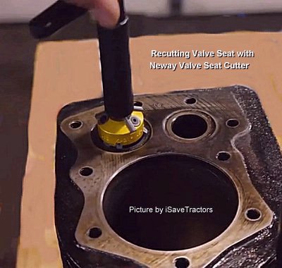
 When regrinding or recutting valve
sears, first cut or regrind the seat with a 46º
[Neway] cutter or [Sioux] grinding stone until it makes
contact 360º around the seat, then use a 31º cutter or grinding
stone to narrow the seat width to factory specs if it's too wide.
When regrinding or recutting valve
sears, first cut or regrind the seat with a 46º
[Neway] cutter or [Sioux] grinding stone until it makes
contact 360º around the seat, then use a 31º cutter or grinding
stone to narrow the seat width to factory specs if it's too wide.
Ever noticed that when looking up valve clearances for an engine, the manufacturer will always show two figures? Example: Intake valve clearance: .008" - .010"; Exhaust valve clearance: .014" - .016". The greater clearance is for a fresh valve job. Because as an engine runs, due to the 30º or 45º angle on the valve face(s) and the 31º or 46º angle on the seat(s), the valves and the seats wears together (break-in period), forming a 30-½º or 45-½º angle on each, which causes the clearances to become slightly lessened. (As the valves wears into the seats, forming a perfect seal, you may notice the engine produces slightly more power.) And for an engine (valves) that's been in use for some time, the valves should be set at the lesser clearance because the valve faces and seats are already worn into each other (broke-in).
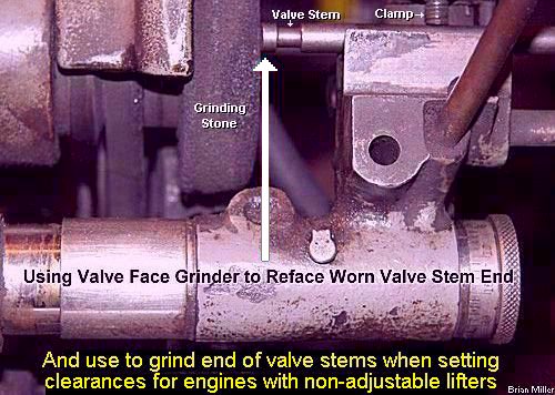 It's also important that the
end of the valve stem is perfectly flat. This will allow for correct valve
adjustment and valve action, especially in an OHV (Over Head Valve) engine
with rocker arms.
It's also important that the
end of the valve stem is perfectly flat. This will allow for correct valve
adjustment and valve action, especially in an OHV (Over Head Valve) engine
with rocker arms.
By the way - I get a lot of engines in my shop that need a valve job performed. Many other small engine repair shops will ignore the valves (or they're not trained to perform professional valve jobs) and assume the hard-starting problem is elsewhere with the engine.
If they're not burnt, then chances are, the valves and seats become warped from the block being heated under normal use after it was new and the metal "takes shape." Aluminum blocks (and heads) are worse than cast iron blocks (and heads). This happens with small engines as well as automotive engines. The block will actually deform a few thousands of an inch, moving the valves off the seats slightly, causing them to leak. Sometimes the cylinder wall(s) will deform a few thousands of an inch, too. Once the "seasoned" block or head takes shape, they won't warp any more. If the valves are leaking, then the valves and seats will need to be recut or reground so they're be in perfect alignment with each other and perpendicular with the valve guides.
Performing a Compression Test on a Stock or High Performance Small Engine with a Compression Tester -
 An accurate compression reading
can't be performed on an engine with an unaltered OEM camshaft due to the
compression release mechanism on one of the cam lobes. Depending on the make
and model of engine, the compression release is either a small hump (early
B&S, certain Tecumseh's, etc.) or mechanical lever/pin (newer B&S,
Kohler, some Tecumseh, etc.) on one of the camshaft lobes that holds either
the intake or exhaust valve open about .050" while the piston is traveling
halfway up in the cylinder on the compression stroke. On OEM camshafts with
a working compression release mechanism and if the valve clearances are adjusted
to specs, the compression release relieves about half the compression air
from the combustion chamber at cranking speed. This is so the engines with
fixed advanced ignition timing will start easier. When attempting to start
an engine with fixed advanced ignition timing, if the compression release
isn't working or if the valve (with the compression release) have too much
stem-to-lifter clearance (out of adjustment), the engine will "kick back"
every time. "Kick back" occurs when the crankshaft suddenly and violently
rebounds or rotates in the opposite direction, which is could bend or break
the starter armature shaft or the aluminum starter housing.
An accurate compression reading
can't be performed on an engine with an unaltered OEM camshaft due to the
compression release mechanism on one of the cam lobes. Depending on the make
and model of engine, the compression release is either a small hump (early
B&S, certain Tecumseh's, etc.) or mechanical lever/pin (newer B&S,
Kohler, some Tecumseh, etc.) on one of the camshaft lobes that holds either
the intake or exhaust valve open about .050" while the piston is traveling
halfway up in the cylinder on the compression stroke. On OEM camshafts with
a working compression release mechanism and if the valve clearances are adjusted
to specs, the compression release relieves about half the compression air
from the combustion chamber at cranking speed. This is so the engines with
fixed advanced ignition timing will start easier. When attempting to start
an engine with fixed advanced ignition timing, if the compression release
isn't working or if the valve (with the compression release) have too much
stem-to-lifter clearance (out of adjustment), the engine will "kick back"
every time. "Kick back" occurs when the crankshaft suddenly and violently
rebounds or rotates in the opposite direction, which is could bend or break
the starter armature shaft or the aluminum starter housing.
On certain B&S, Kohler models K90/K91, K141, K160/K161, K181, L161, L181, M8, some Tecumseh, etc. engines without adjustable lifters, but with an automatic (mechanical) compression release (ACR) on the camshaft, there is no way to perform an accurate compression test with a compression tester. All that can be done to test the compression is rotate the flywheel quickly by hand in the opposite direction of normal engine rotation. If it rebounds sharply, the engine has adequate compression. FYI - If you have a Kohler 7-16hp ACR camshaft that was broke in two by a thrown connecting rod, save the spring off of it. It can be used on another good cam that may not have one. Or if your ACR spring places little or weak pressure against the flyweights/levers, it can be re-bent or reshape to its original condition to place sufficient tension against the flyweights/levers.
There are two ways to perform an accurate compression test with a compression tester on the Kohler K-series and Magnum engine models K241, M10, K301, M12, K321, M14, K341, M16 and K361:
To obtain an accurate compression pressure reading, perform the test with a fully charged battery, a starter that's in good condition and the throttle in the wide open position. Or with pull rope engines, place the throttle in the wide open position. When performing a compression test with a gauge on an air-cooled engine, keep in mind that, depending on how the engine is built, the compression ratio or the compression pressure can vary from one engine to another. It depends on the size of the bore and stroke, the volume of the combustion chamber in the cylinder head, if the camshaft has a compression release or not and how much duration the cam lobes have. If a cam has a compression release mechanism, being approximately half the compression is released from the combustion chamber at cranking speed, the compression reading will be cut approximately in half.
When performing a compression test on an engine under compression, the K241 and M10 Kohler can be from 98 to 150 psi. On a K301 and M12, it can be from 112 to 170 psi. On a K321 and M14, it can range from 120 to 190 psi. And on a K341 and M16, it can be from 127 up to 192 psi.
And cranking speeds, a long duration cam will relieve some of the combustion chamber pressure, resulting in a lower than normal reading. The more the duration, the lower the reading. Calculate the reading with the duration of the cam in the engine against the duration of a stock OEM cam. Example: If the compression pressure is 100 psi, multiple 100 by 285 (duration of cam that's in the engine) and then divide the answer by 223 degrees (duration of a stock OEM cam), which gives 128 psi.
And Remember...
Rather if it's for general lawn and garden use, competition racing or competition pulling, the parts inside any fresh-built engine needs to fully wear into each other. This is otherwise known as engine break-in. Rings don't "seat." They wear-into the cylinder wall, and wear-in rather quickly. But the valve faces on the other hand, takes longer to wear into the seats. The valve faces are ground at either 30º or 45º angle, and the seats are ground or cut at either 31º or 46º angle (to match the valve face). As they wear into each other, they form a 30½º or 45½º angle. The harder material valves are made of, the longer it takes for them to "seat." With rotators, it takes less time for the valves to "seat" or wear-in. Some pullers (customers) tell A-1 Miller's that engines I built for them run stronger every time they pull them without making any major adjustments or changes. This is because the valves are wearing into the seats to better seal in the compression. I remember a few years ago when I performed a valve job on my 1985 Chevy 350 truck engine. The engine ran good and strong afterwards, but I noticed after about 1,000 miles or so, it produced a little more power. This is because the valve faces wore into the seats, forming a perfect seal. So just to let you know, a rebuilt engine with a fresh valve job will not produce full power the first few times it's ran, even in a dyno test.
Just cleaning
the valves and lapping them in (with a valve
lapping tool and compound), then assume the engine will run fine for
many years without problems is definitely not how a professional valve job
is performed.
Valve grinding compound, which can be purchased online
and at virtually any auto parts store, is not meant for "grinding valves".
I realize it reads on the label: "Valve Grinding Compound," but this
is wrong because it doesn't regrind valves (or seats) whatsoever. A valve
seat cutter/grinder and valve refacer grinding machine is meant to do this.
The
valve grinding compound (which can be purchased online
and at virtually any auto parts store) is actually used to create a rough
surface on the valve face and seat so they'll wear into each other as they
break in, forming a perfect seal to keep the valves from leaking out compression.
 Remember, when/if you have a
repair shop perform a valve job, be sure to ask them how it's done. In other
words, test their knowledge. If they say that the valves be removed, cleaned
up, lapped in, then set the clearance, this is not the correct way to do
it. Due to normal engine heat and "twisting" of the engine block (which is
normal and happens to all flathead engines and OHV (Over Head Valve) cylinder
heads), valve heads become warped. New engine blocks (or cylinder head on
OHV engines) rather it be cast iron or aluminum, will sometimes become
"distorted" (bend and twist) a few thousands of an inch when it gets hot
from normal use. The valves will become warped to match the warped block
(or head). Therefore, to prevent loss of valuable compression and engine
power, the valve faces will need to be reground in a valve grinding machine
and the seats recut or reground with a valve seat cutter or grinder to put
everything back in correct alignment. The head will literally move a few
thousands of an inch offcenter of the valve stem. Therefore, the valve faces
must be reground in a valve grinding machine, or if a valve is severely burnt,
it should be replaced. And again, due to normal engine heat, the valve seats
will literally move a few thousands of an inch offcenter of the
valve guide. Therefore, the seats must be reground
with a seat grinder or cutter so the valve faces will seal 360º around
the seats. (And always wear
eye protection whenever working with metal!)
Remember, when/if you have a
repair shop perform a valve job, be sure to ask them how it's done. In other
words, test their knowledge. If they say that the valves be removed, cleaned
up, lapped in, then set the clearance, this is not the correct way to do
it. Due to normal engine heat and "twisting" of the engine block (which is
normal and happens to all flathead engines and OHV (Over Head Valve) cylinder
heads), valve heads become warped. New engine blocks (or cylinder head on
OHV engines) rather it be cast iron or aluminum, will sometimes become
"distorted" (bend and twist) a few thousands of an inch when it gets hot
from normal use. The valves will become warped to match the warped block
(or head). Therefore, to prevent loss of valuable compression and engine
power, the valve faces will need to be reground in a valve grinding machine
and the seats recut or reground with a valve seat cutter or grinder to put
everything back in correct alignment. The head will literally move a few
thousands of an inch offcenter of the valve stem. Therefore, the valve faces
must be reground in a valve grinding machine, or if a valve is severely burnt,
it should be replaced. And again, due to normal engine heat, the valve seats
will literally move a few thousands of an inch offcenter of the
valve guide. Therefore, the seats must be reground
with a seat grinder or cutter so the valve faces will seal 360º around
the seats. (And always wear
eye protection whenever working with metal!)
Valves can leak! For example, if fuel sprays out of the carburetor on a opposed twin cylinder engine when it's running at fast speed, then the following causes are.
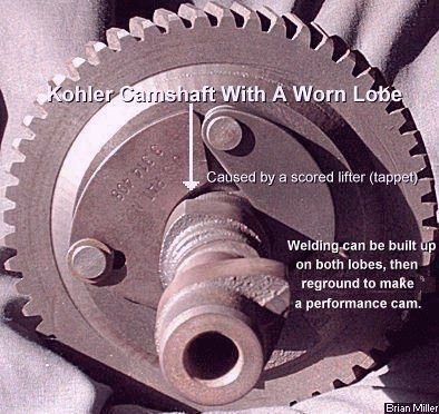 But if a valve isn't opening
or opening very little when the engine is cranked over, then chances are,
the nose or toe on a lobe on the camshaft is wore down. This happens when
water gets in the crankcase and over time, condensation attaches itself to
the base of the lifter, rusting and pitting it. While the engine is running,
the rusted and pitted lifter wears (or grinds) the lobe until it's wore down
or "rounded." This sort of thing will also prevent a single cylinder engine
from revving up.
But if a valve isn't opening
or opening very little when the engine is cranked over, then chances are,
the nose or toe on a lobe on the camshaft is wore down. This happens when
water gets in the crankcase and over time, condensation attaches itself to
the base of the lifter, rusting and pitting it. While the engine is running,
the rusted and pitted lifter wears (or grinds) the lobe until it's wore down
or "rounded." This sort of thing will also prevent a single cylinder engine
from revving up.
About Lead Content in Gasoline -
Lead in gas was actually meant for older (pre-1970) automotive engines because they had soft cast iron valve seats. The cylinder heads were made of cast iron and the seats were cut or ground directly into the head with no hardened inserts. These seats was not heat-treated and would wear when no lead is present in gas. However, the later model automobile engine valve seats (1971-present) are heat-treated and last a lot longer. The seats were still cut or ground in the [cast iron] heads, but are heat-treated. The aluminum automotive heads have heat-treated steel inserts for valve seats. And virtually ALL small engine valve seats come from the factory heat-treated. They are steel inserts, and rarely wear when no lead is present in gas.
How to Perform a Professional Valve Job - [Top of Page]
 First of all, performing a
professional valve job will restore full compression, which will allow the
engine to start quicker, idle smoothly, rev up with no hesitation, produce
lots of power, and run for a long time without stalling or dying (when the
ignition timing and carburetor adjustments are set correctly, too). So to
gain more power and torque from virtually any flathead single or opposed
twin cylinder engine, perform a professional valve job and the valve clearances
will need to be increased. Resurface the cylinder heads on a flat sanding
disc to ensure 100% head gasket sealing. Nothing else may be needed to be
done to the engine, except for perhaps a professional tune up. Many opposed
twin cylinder engines have inadequate valve clearances and this robs the
engine of proper operation and valuable power. Perform a professional valve
job, and set the clearances (between the valve stems and lifters) at .010"
for the intake and .014" for the exhaust. After increasing the valve clearances,
the engine will start quicker, idle better and produce more power at low
and high RPM.
First of all, performing a
professional valve job will restore full compression, which will allow the
engine to start quicker, idle smoothly, rev up with no hesitation, produce
lots of power, and run for a long time without stalling or dying (when the
ignition timing and carburetor adjustments are set correctly, too). So to
gain more power and torque from virtually any flathead single or opposed
twin cylinder engine, perform a professional valve job and the valve clearances
will need to be increased. Resurface the cylinder heads on a flat sanding
disc to ensure 100% head gasket sealing. Nothing else may be needed to be
done to the engine, except for perhaps a professional tune up. Many opposed
twin cylinder engines have inadequate valve clearances and this robs the
engine of proper operation and valuable power. Perform a professional valve
job, and set the clearances (between the valve stems and lifters) at .010"
for the intake and .014" for the exhaust. After increasing the valve clearances,
the engine will start quicker, idle better and produce more power at low
and high RPM.
To do a poor quality valve job, some people will remove the valves, clean them thoroughly, then use valve grinding compound (which can be purchased online and at virtually any auto parts store) to reseal them to the seats, then if they think of it, reset the valve clearances. Doing this might help an engine run better, but it's not how to perform a professional and/or performance valve job so the engine will start quicker, idle smoothly, accelerate without hesitation, and produce full power at higher RPM.
Valve clearances in the Kohler Engine Specifications and Tolerances charts are given with a lesser and greater clearance. Example: .008"-.010" intake, and .017"-.019" exhaust. The lesser clearance is for worn-in valve faces and seats, and the greater clearance is for freshly-ground valve faces and seats, or new valves with fresh-reground seats. Because as a freshly-ground valve face or new valve wear into the seat, the clearance between the valve stem and lifter is lessened.
To perform a professional valve job on a opposed twin cylinder flathead B&S or Kohler engine, the parts that will be needed are: two head gaskets, two crankcase breather gaskets, intake manifold mounting gaskets and valve stem seals (for intake valves only). New valve guides, especially for the exhaust valves, may also be needed. But that's to be determined once the valves are removed. The valve faces and valve seats angles are to be reground or recut at 45° (intake valve face for Kohler), 30° (intake valve face for B&S) and 46° (intake and exhaust seats for Kohler and exhaust seat only for B&S), 31° (intake seat for B&S), respectively. If you can't do this yourself, a local automotive machine shop can do it for you. You'll need to take the engine or tractor to the shop to have the valve seats reground or recut. Make sure they're reground or recut at the proper angle, too! And it'll be a good idea to have both cylinder heads resurfaced on a on a wide, flat belt- or disc-sander/grinder to remove any warpage and restore flatness, and to ensure 100% head gasket sealing. The head bolts can be reused. They rarely go bad.
The tools that's required to perform a professional valve job are as follows:
To perform a professional valve job correctly the first time so the engine will start quicker, idle smoothly and rev to full RPMs:
 First
rotate the crankshaft until the piston is at top dead center (TDC) on the
compression stroke. Or if the crank is out of the block (during an engine
rebuild), rotate the camshaft until both valves are fully closed. If it's
a twin- or multi-cylinder engine, do this for each cylinder.
First
rotate the crankshaft until the piston is at top dead center (TDC) on the
compression stroke. Or if the crank is out of the block (during an engine
rebuild), rotate the camshaft until both valves are fully closed. If it's
a twin- or multi-cylinder engine, do this for each cylinder.
 If a valve stem is bent,
chances are, it can be straightened and the valve can be reused. I repair
bent valves in my big metal lathe with success. Here's how to do
it:
If a valve stem is bent,
chances are, it can be straightened and the valve can be reused. I repair
bent valves in my big metal lathe with success. Here's how to do
it:

 First of all, if there's a crack
in the valve stem, it must be replaced, especially when used in an
OHV (Over Head Valve) engine. It's best to inspect the stem for a hairline
crack with a strong magnifying glass or better yet, a powerful
microscope. Do not attempt to
weld up a cracked valve stem, especially an exhaust valve and after straightening
it! It will break later!
First of all, if there's a crack
in the valve stem, it must be replaced, especially when used in an
OHV (Over Head Valve) engine. It's best to inspect the stem for a hairline
crack with a strong magnifying glass or better yet, a powerful
microscope. Do not attempt to
weld up a cracked valve stem, especially an exhaust valve and after straightening
it! It will break later!
 Use steel feeler gauges to set
the valve clearances. For the K241-K341 engines, for general lawn and garden
use, the valve clearances are: .008"-.010" for the intake and .017"-.019"
for the exhaust with the piston at TDC on the compression stroke. This is
when both valves are fully closed. For competition pulling, set the valve
clearances at .010" for the intake and .014" for the exhaust.
Use steel feeler gauges to set
the valve clearances. For the K241-K341 engines, for general lawn and garden
use, the valve clearances are: .008"-.010" for the intake and .017"-.019"
for the exhaust with the piston at TDC on the compression stroke. This is
when both valves are fully closed. For competition pulling, set the valve
clearances at .010" for the intake and .014" for the exhaust.
 When checking the valve lash
on any engine, the piston in the cylinder for the valves that you're checking
(on multiple cylinder engines) must be at top dead center (TDC) on the
compression stroke. This places the lifters on the base circle of the cam
lobes. The reason there's a valve lash is so the valves can fully close,
sealing in the compressed air/fuel mixture in the combustion chamber. Too
little lash, and some of the compression will escape through one or both
valves, and in over time, a valve may burn. Too much lash, and the valves
won't open fully, preventing the engine from producing full power.
When checking the valve lash
on any engine, the piston in the cylinder for the valves that you're checking
(on multiple cylinder engines) must be at top dead center (TDC) on the
compression stroke. This places the lifters on the base circle of the cam
lobes. The reason there's a valve lash is so the valves can fully close,
sealing in the compressed air/fuel mixture in the combustion chamber. Too
little lash, and some of the compression will escape through one or both
valves, and in over time, a valve may burn. Too much lash, and the valves
won't open fully, preventing the engine from producing full power.
 use a
valve lapping tool to lap the valves in
the seats (use this tool to rotate each valve back and forth with both hands)
until the "grinding sound" goes away. This process is important. It seals
the valves to the seats.
After lapping in the valves, remove
the valves and thoroughly clean the compound material from the valves and
seats, then inspect the valve faces to see if the compound made full contact
of 360º around each valve face and seat. If it didn't, then the valve
is warped, or the face or seat wasn't ground correctly and will need to be
re-done.
use a
valve lapping tool to lap the valves in
the seats (use this tool to rotate each valve back and forth with both hands)
until the "grinding sound" goes away. This process is important. It seals
the valves to the seats.
After lapping in the valves, remove
the valves and thoroughly clean the compound material from the valves and
seats, then inspect the valve faces to see if the compound made full contact
of 360º around each valve face and seat. If it didn't, then the valve
is warped, or the face or seat wasn't ground correctly and will need to be
re-done.
 chainsaw bar tip grease gun to make this much easier and
less messy), stick one half of a keeper to it, apply another dab of grease
inside the keeper, then carefully place the keeper on the valve stem (in
the right direction). Do it this way with each keeper half. The grease securely
holds the keepers/locks/collets to the valve stem
until the retainer can be released over them.
chainsaw bar tip grease gun to make this much easier and
less messy), stick one half of a keeper to it, apply another dab of grease
inside the keeper, then carefully place the keeper on the valve stem (in
the right direction). Do it this way with each keeper half. The grease securely
holds the keepers/locks/collets to the valve stem
until the retainer can be released over them.
What Are Valve Rotators and Why Are They Used?
 For a non-pulling engine, valve rotators help prevent valves
from burning by rotating the valve slightly as it opens to scrape away any
carbon deposits from the valve face and seat. If an engine didn't come with
valve rotators (most early Kohler engines didn't), they can be installed
instead of the stamped steel non-rotator retainers. Many automotive engines
use valve rotators, too. A rotator should be used with the exhaust valve
because that's the one where the carbon exits the combustion chamber, and
is optional for use with the intake valve. Rotators can be used in any K141-K341
Kohler engine. It's important that a rotator be used with the 1-9/16"
uncompressed height OEM valve spring to prevent coil bind at full valve lift,
which may result in cam breakage. Stamped or machined steel retainers require
a 1-3/4" uncompressed height OEM spring. If the shorter 1-9/16" spring is
used with a non-rotator retainer, the valve(s) may float, and/or the
keepers/locks/collets may become dislodged from the
valve stem at higher RPM. Although valve rotators are extremely strong,
competition pulling engines don't require them because they don't run long
enough for carbon to build up in the combustion chamber. By the way - valve
keepers usually don't wear or get damaged because they don't rotate on the
valve stem. To check yours, with a valve out of the engine, install a valve
retainer or rotator on the valve, then the keepers, and then pull back hard
on the retainer or rotator. If the retainer or rotator holds or squeezes
the keepers tight in the groove, then they can be reused.
For a non-pulling engine, valve rotators help prevent valves
from burning by rotating the valve slightly as it opens to scrape away any
carbon deposits from the valve face and seat. If an engine didn't come with
valve rotators (most early Kohler engines didn't), they can be installed
instead of the stamped steel non-rotator retainers. Many automotive engines
use valve rotators, too. A rotator should be used with the exhaust valve
because that's the one where the carbon exits the combustion chamber, and
is optional for use with the intake valve. Rotators can be used in any K141-K341
Kohler engine. It's important that a rotator be used with the 1-9/16"
uncompressed height OEM valve spring to prevent coil bind at full valve lift,
which may result in cam breakage. Stamped or machined steel retainers require
a 1-3/4" uncompressed height OEM spring. If the shorter 1-9/16" spring is
used with a non-rotator retainer, the valve(s) may float, and/or the
keepers/locks/collets may become dislodged from the
valve stem at higher RPM. Although valve rotators are extremely strong,
competition pulling engines don't require them because they don't run long
enough for carbon to build up in the combustion chamber. By the way - valve
keepers usually don't wear or get damaged because they don't rotate on the
valve stem. To check yours, with a valve out of the engine, install a valve
retainer or rotator on the valve, then the keepers, and then pull back hard
on the retainer or rotator. If the retainer or rotator holds or squeezes
the keepers tight in the groove, then they can be reused.
Most Kohler engines have the short valve spring (1-9/16") with the rotator on the exhaust valve, and the long spring (1-3/4") with the stamped retainer on the intake valve.
How to Perform a Professional Valve Job on a B&S or Kohler Opposed Twin Cylinder Engine -
| To gain more power and torque from virtually any flathead two or opposed
twin cylinder engine, perform a professional valve job and the valve clearances
will need to be increased. Resurface the cylinder heads on a flat sanding
disc to ensure proper head gasket sealing. Nothing else may be needed to
be done to the engine, except for perhaps a professional tune up. Many opposed
twin cylinder engines have inadequate valve clearances and this robs the
engine of proper operation and valuable power. Perform a professional valve
job, and set the clearances (between the valve stems and lifters) at .010"
for the intake and .014" for the exhaust. After increasing the valve clearances,
the engine will start quicker, idle better and produce more power at low
and high RPM.
To perform a professional valve job on a opposed twin cylinder flathead B&S or Kohler engine, the parts that will be needed are: two head gaskets, two crankcase breather gaskets, intake manifold mounting gaskets and valve stem seals (for intake valves only). New valve guides, especially for the exhaust valves, may also be needed. But that's to be determined once the valves are removed. A quality-made valve spring compressor tool is required to remove and reinstall the valves. The valve faces and valve seat angles are to be recut or reground at 45º (intake valve face for Kohler), 30º (intake valve face for B&S) and 46º (intake and exhaust seats for Kohler and exhaust seat only for B&S), 31º (intake seat for B&S), respectively. If you can't do this yourself, a local automotive machine shop can do it for you. You'll need to take the engine or tractor to the shop to have the valve seats recut or reground. Make sure they're recut or reground at the proper angle, too! And it'll be a good idea to have both cylinder heads resurfaced on a flat sanding disc to ensure 100% head gasket sealing. The head bolts can be reused. They rarely go bad. |
Advertisement: (Prices are subject to change without notice.) FYI - Due to new EPA rules and regulations, Kohler (and many other small engine manufacturers) are phasing out many parts for their flathead and cast iron block engines. But the parts in question may be available in aftermarket.
| Click here to contact A-1 Miller's Performance Enterprises to place an order, send your parts for repairing, and/or for FREE professional and honest technical customer service assistance and support and payment options. Please contact A-1 Miller's if you need a part or parts, or service(s) performed that's not listed or mentioned in this website. | ||
 Intake Valve. Fits
Kohler engine models KT90/KT91. Head diameter: 15/16". New Old Stock.
Discontinued Kohler part # 220008-S. $32.00 each, plus shipping &
handling. (When available.) Intake Valve. Fits
Kohler engine models KT90/KT91. Head diameter: 15/16". New Old Stock.
Discontinued Kohler part # 220008-S. $32.00 each, plus shipping &
handling. (When available.)
Exhaust Valve. Fits Kohler engine models KT90/KT91. OEM Kohler part # 220009-S. $60.55 each, plus shipping & handling. NOTE: Before lapping in valves, it's best to have the valve seats recut or reground so they'll be in correct alignment with the centerline of the valve guides. Otherwise, the valves may not make a full 360º contact with the seats, resulting in leakage and the engine will lose compression, be hard to start, lose power and possibly make a popping sound through the carburetor or out the exhaust at idle speed. And be sure to set the clearances correctly, too. And if the end of the valve stem is accidentally ground too short, it can be made long again by building up welding with a MIG or TIG welder, then ground to the correct valve clearance.
Intake Valves. Fits Kohler engine models K141, K160/K161 K181, L161, L181, M8. Dimensions: head diameter: 1-3/8"; overall length: 4.065"; stem diameter: .309"; 45º face angle.
NOTE: Before lapping in valves, it's best to have the valve seats recut or reground so they'll be in correct alignment with the centerline of the valve guides. Otherwise, the valves may not make a full 360º contact with the seats, resulting in leakage and the engine will lose compression, be hard to start, lose power and possibly make a popping sound through the carburetor or out the exhaust at idle speed. And be sure to set the clearances correctly, too. And if the end of the valve stem is accidentally ground too short, it can be made long again by building up welding with a MIG or TIG welder, then ground to the correct valve clearance.
1-3/8" Diameter Intake Valves. Fits Kohler engine models K241, M10, K301, M12, K321, M14, K341, M16, K482, K532 and K582. Dimensions - Head diameter: 1-3/8"; Length: 4.640"; Stem diameter: .3095"; Face angle: 45º.
1-3/8" Diameter Exhaust Valves for later model K321's, M14 (suffix "D" and later), K341, M16, K532 and K582 (for K582 after serial # 9165450). Dimensions - Head diameter: 1.373; Length: 4.639; Stem diameter: .3075; Face Angle: 45º.
NOTE: Before lapping in valves, it's best to have the valve seats recut or reground so they'll be in correct alignment with the centerline of the valve guides. Otherwise, the valves may not make a full 360º contact with the seats, resulting in leakage and the engine will lose compression, be hard to start, lose power and possibly make a popping sound through the carburetor or out the exhaust at idle speed. And be sure to set the clearances correctly, too. And if the end of the valve stem is accidentally ground too short, it can be made long again by building up welding with a MIG or TIG welder, then ground to the correct valve clearance.
8mm (.315") Chucking Reamer. Use to enlarge valve guides for installation of oversize or aftermarket valves with an 8mm valve stem in Kohler engine models K361, KT19, KT19 Series II, M20 and MV20, or 1.720" oversize valve in 10-16hp Kohler engines. $20.00 each, plus shipping & handling.
NOTE: Before lapping in valves, it's best to have the valve seats recut or reground so they'll be in correct alignment with the centerline of the valve guides. Otherwise, the valves may not make a full 360º contact with the seats, resulting in leakage and the engine will lose compression, be hard to start, lose power and possibly make a popping sound through the carburetor or out the exhaust at idle speed. And be sure to set the clearances correctly, too. And if the end of the valve stem is accidentally ground too short, it can be made long again by building up welding with a MIG or TIG welder, then ground to the correct valve clearance.
Intake Valves. Each valve listed below fits Kohler engine models KT17 (first design), KT17 Series II, MV16, M18 and MV18. Replaces discontinued Kohler part #'s 52 016 05-S (listed for M18, MV18), 52 017 01-S (listed for KT17), 52 017 02-S (listed for KT17), 52 017 03-S (listed for KT17), 52 017 05-S (listed for KT17), 52 017 07-S (listed for MV16, M18) and 52 017-08-S (listed for MV16, M18). Overall length: 3.641".
Exhaust Valves. Each valve listed below fits Kohler engine models KT17 (first design), KT17 Series II, MV16, M18 and MV18. Dimensions: head diameter: 1.373"; overall length: 3.641"; stem diameter: .3075".
Intake Valves. Fits Kohler engine models KT19 first design, KT19 Series II, KT21, M20 and MV20. Replaces discontinued Kohler part #'s 52 016 02-S, 52 017 03 (listed for KT19), 52 017 07-S, 52 017 08-S. Overall length: 3.926".
Exhaust Valves. Fits Kohler engine models KT19 first design, KT19 Series II, KT21, M20 and MV20. Replaces discontinued Kohler part #'s 52 016 02-S, 52 017 03, 52 017 07-S, 52 017 08-S. Overall length: 3.926".
NOTE: Before lapping in valves, it's best to have the valve seats recut or reground so they'll be in correct alignment with the centerline of the valve guides. Otherwise, the valves may not make a full 360º contact with the seats, resulting in leakage and the engine will lose compression, be hard to start, lose power and possibly make a popping sound through the carburetor or out the exhaust at idle speed. And be sure to set the clearances correctly, too. And if the end of the valve stem is accidentally ground too short, it can be made long again by building up welding with a MIG or TIG welder, then ground to the correct valve clearance.
è New valves for other makes and models of small engines are also available. |
||
| Valve Guides -
FYI - Valve guides are made of
either cast iron or bronze, and not steel. Cast iron and bronze are very
hard and porous metals. They absorb oil and lubricate the valve stems for
longer wear. NOTE: The alternative to installing
new replacement OEM-type valve guide(s) is to have the old [worn] guide(s)
reamed for installation of thin-wall bronze sleeves/liners (bushings), which
can be installed by an experienced and reputable automotive machine shop.
Thin-wall bronze valve guides are a low-cost and actually works better than
replacing the OEM guide in most engines. Bronze lasts longer than cast iron
guides because it is harder material and it retains more oil for better
lubrication of the valve stem.
Installing CLASSIC Bronze-Liners
[Return To Previous Paragraph, Section
or Website]
|
||
 A-1
Miller's Valve Guide Removal and Installation Tool for use with all Kohler
K-series and Magnum engines. IMPORTANT: The engine block could crack if
guides are removed or installed with a hydraulic press! Therefore, it's
best to use a big, heavy hammer (with this tool) to drive out the old guide
into the valve spring compartment and use the same hammer (with this tool)
to install the new guide externally from inside the valve pocket. When installing
the new guide, be sure to hammer straight down in alignment with the guide
bore hole and not at an angle. Hitting the guide at an angle could cause
it to break. Install new guides until flush with the valve pocket. This tool
can be used with either OEM Kohler and aftermarket offset valve guides. Machined
at a 90º angle where the pilot meets the shank. Dimensions: .300" pilot
x 1/2" diameter shank x 5" overall length. A-1 Miller part. $20.00
each, plus shipping & handling. [Return
To Previous Paragraph, Section or Website] A-1
Miller's Valve Guide Removal and Installation Tool for use with all Kohler
K-series and Magnum engines. IMPORTANT: The engine block could crack if
guides are removed or installed with a hydraulic press! Therefore, it's
best to use a big, heavy hammer (with this tool) to drive out the old guide
into the valve spring compartment and use the same hammer (with this tool)
to install the new guide externally from inside the valve pocket. When installing
the new guide, be sure to hammer straight down in alignment with the guide
bore hole and not at an angle. Hitting the guide at an angle could cause
it to break. Install new guides until flush with the valve pocket. This tool
can be used with either OEM Kohler and aftermarket offset valve guides. Machined
at a 90º angle where the pilot meets the shank. Dimensions: .300" pilot
x 1/2" diameter shank x 5" overall length. A-1 Miller part. $20.00
each, plus shipping & handling. [Return
To Previous Paragraph, Section or Website] |
||
 High
Quality, High Speed Steel Chucking Reamers. Precision ground to provide
correct stem-to-guide clearance. Will not allow valve stem to be too loose
or too tight in guide. When reaming guide, use an electric hand drill with
plenty of oil in guide. Before installing valve, apply motor oil on stem
for lubrication to reduce wear to guide and prevent valve from sticking.
[Return To Previous Paragraph, Section
or Website] High
Quality, High Speed Steel Chucking Reamers. Precision ground to provide
correct stem-to-guide clearance. Will not allow valve stem to be too loose
or too tight in guide. When reaming guide, use an electric hand drill with
plenty of oil in guide. Before installing valve, apply motor oil on stem
for lubrication to reduce wear to guide and prevent valve from sticking.
[Return To Previous Paragraph, Section
or Website]
|
||
 Valve
Stem Seals. Required to prevent crankcase oil from draining down into
(OHV) or being suctioned into (flatheads) the combustion chamber through
the guide. Silicone rubber w/metal clamp. NOTE: Apply clean motor oil,
gear oil or lubricating grease on valve stem before inserting valve through
seal to provide lubrication of the stem, guide and seal. Dimensions:
5/16" I.D. (stem) x .500" I.D. (guide) x .600" O.D. NOTE: Some early production
KT17 models do not use valve stem seals. Valve
Stem Seals. Required to prevent crankcase oil from draining down into
(OHV) or being suctioned into (flatheads) the combustion chamber through
the guide. Silicone rubber w/metal clamp. NOTE: Apply clean motor oil,
gear oil or lubricating grease on valve stem before inserting valve through
seal to provide lubrication of the stem, guide and seal. Dimensions:
5/16" I.D. (stem) x .500" I.D. (guide) x .600" O.D. NOTE: Some early production
KT17 models do not use valve stem seals.
|
||
| Click here to contact A-1 Miller's Performance Enterprises to place an order, send your parts for repairing, and/or for FREE professional and honest technical customer service assistance and support and payment options. | ||
How to Repair a Loose Valve Seat in an Aluminum Block Flathead Engine and OHV Aluminum Cylinder Head - [Top of Page]
 A loose [exhaust] valve seat
is a common problem with the Briggs & Stratton opposed twin cylinder
flathead engines, and certain newer OHV small engines. What cause the valve
seat to loosen in these engines is the main jet in the carburetor gets partially
clogged with built-up debris (tiny particles that passed through the fuel
filter) in the float bowl, which lean out the air/fuel mixture and the engine
had to be ran on half-choke. This overheats the combustion chambers, which
caused the seat to loosen. On the B&S opposed engines, it always happens
to the #2 cylinder, the one furthest away from the flywheel. To fix this,
first, the main jet will need to be cleared out with 150± PSI compressed
air. And then the valve seat can be peened in back in its counterbore with
a flat punch and medium size hammer. But if the seat fits loose in the
counterbore, after it's been peened in, the centerline of the seat will be
offset with the centerline of the valve guide and the valve will not fully
close and seal around the seat. If this is the case, then the engine block
will need to be precision-machined with specialized equipment for installation
of an oversize O.D. hardened valve seat, and the same [size] valve can be
reused.
A loose [exhaust] valve seat
is a common problem with the Briggs & Stratton opposed twin cylinder
flathead engines, and certain newer OHV small engines. What cause the valve
seat to loosen in these engines is the main jet in the carburetor gets partially
clogged with built-up debris (tiny particles that passed through the fuel
filter) in the float bowl, which lean out the air/fuel mixture and the engine
had to be ran on half-choke. This overheats the combustion chambers, which
caused the seat to loosen. On the B&S opposed engines, it always happens
to the #2 cylinder, the one furthest away from the flywheel. To fix this,
first, the main jet will need to be cleared out with 150± PSI compressed
air. And then the valve seat can be peened in back in its counterbore with
a flat punch and medium size hammer. But if the seat fits loose in the
counterbore, after it's been peened in, the centerline of the seat will be
offset with the centerline of the valve guide and the valve will not fully
close and seal around the seat. If this is the case, then the engine block
will need to be precision-machined with specialized equipment for installation
of an oversize O.D. hardened valve seat, and the same [size] valve can be
reused.
FYI - The correct method (and really the only true way) to install a larger O.D. valve seat is the counterbore will need to be machined-bored .005" smaller than the O.D. of the replacement seat with a special carbide cutter that's positioned in a hardened steel pilot shaft that's chucked in a special valve seat counterbore cutting machine. This guarantees the new installed seat will be in perfect alignment with the valve guide and perpendicular with the surface of the block or head. Many automotive engine machine shops should be able to perform this task. They can also get oversize bronze valve seats because certain newer cars with an aluminum cylinder head use them. If they say they can't do any of this, then they are not trying hard enough, or there's not enough money in it for them just to install one seat. Please let me know if you're interested in this service.
The below is how to peen in the valve seat in the engine block or [OHV] cylinder head.
 The valve will need to be removed
from the block or head.
The valve will need to be removed
from the block or head.
The reason a valve seat loosens in a flathead aluminum engine block or OHV cylinder head is because either the factory didn't press the metal tight enough around the seat or the aluminum expanded just enough with engine heat causing the seat to loosen. After the seat is securely tightened back in place, it shouldn't give any more trouble.
NOTE: Sometimes the seat can loosen so much, the counterbore where the seat rests will become enlarged. In fact, it can be too large to peen the seat back in place. When this happens, the counterbore will need to be bored for an oversized outside diameter seat. It takes a reputable machine shop/business to perform this type of repair.
On the Briggs & Stratton OHV engines, if one of the pushrods for the valves become bent, it can be successfully straightened (gently, by hand), and reused. This is a common thing with these engines. Anyway, to check the straightness of the pushrod, place it on a perfectly flat, smooth surface and rotate it across the surface by hand. Continue to straighten it (again, gently by hand) until it rotates across the flat surface freely. What causes the pushrod to bend is due to insufficient clearance between the valve stem and guide. When the engine reaches operating temperature, due to normal heat and friction, the stem will swell up a few thousandths of an inch, and seize or "bind up" in the guide. Sometimes when this happens, due to the OEM low pressure valve spring, the valve will remain in the open position. To prevent this from ever happening again, remove both valves from the head, and chuck each valve in a metal lathe or drill press, and then use fine emery cloth to "wear down" the stems a few thousandths (.001"-.0015") of an inch. Use a micrometer or dial or digital caliper to accurately measure the diameter of each stem before and after the machining. And while valves are out of the head, it'll be a good idea to peen in the valve seats (with a flat punch and medium size hammer) to prevent them from possibly loosening and falling out in the future. (This is another common problem with these engines.) "Peening" is when the aluminum is "pounded" 360º around the seat so it will remain tight. Be sure to stagger the punches to begin with so the seat will be centered and won't sit crooked in the head. [Top of Page] |
Advertisement: Prices are subject to change without notice.
| Click here to contact A-1 Miller's Performance Enterprises to place an order, send your parts for repairing, and/or for FREE professional and honest technical customer service assistance and support and payment options. Please contact A-1 Miller's if you need a part or parts, or service(s) performed that's not listed or mentioned in this website. [Top of Page] | |
| A-1 Miller's Professional Valve
Repair Service for Kohler Engine Model K361 Cylinder Head. This service
is for an engine that does not blow blue smoke out the exhaust and burn/consume
oil. Performing a professional valve job restores full compression, which
allows the engine to start quicker, idle smoothly (without stalling), and
(if the carburetor adjustments and ignition timing are set correctly, too),
it will rev quicker and produce full power at top governed speed.
Click or tap here for cylinder
head bolt torque specs. And if you've ever wondered how the K361 rocker
arms receive plenty of oil to keep them lubricated, when the engine is running
at full governed speed, internal air pressure from the downward stroke of
the piston force crankcase oil through the pushrod tubes into the rocker
arm chamber. Prices are subject to change without notice.
|
|
 Crankcase Breather
Assembly/Cover Gaskets. Fits Kohler engine models K90/K91. Crankcase Breather
Assembly/Cover Gaskets. Fits Kohler engine models K90/K91.
|
|
 Crankcase Breather and Air
Cleaner Neoprene Rubber Seal. Fits Kohler engine models K90/K91, K241, K301,
K321, K341, K361, K582, M10, M12, M14, M16, MV16, M18, MV18, M20, MV20, CH640,
CH730, CH740, CV670, CV680, CV730 and CV740. Dimensions: 1/4" I.D. x 1/2"
O.D. x 9/16" length. FYI - A reinforced rubber fuel hose of the same size
can be substituted for this part. OEM Kohler part #'s 220369-S and 231032-S.
$5.65 each, plus shipping & handling. Crankcase Breather and Air
Cleaner Neoprene Rubber Seal. Fits Kohler engine models K90/K91, K241, K301,
K321, K341, K361, K582, M10, M12, M14, M16, MV16, M18, MV18, M20, MV20, CH640,
CH730, CH740, CV670, CV680, CV730 and CV740. Dimensions: 1/4" I.D. x 1/2"
O.D. x 9/16" length. FYI - A reinforced rubber fuel hose of the same size
can be substituted for this part. OEM Kohler part #'s 220369-S and 231032-S.
$5.65 each, plus shipping & handling. |
 Crankcase Breather and Air
Cleaner Neoprene Rubber Seal. Fits Kohler engine models K141, K160/K161,
K181, KV161,
L160/L161, L181, M8, MV18
MV20, CH18, CH20, CH22, CH25, CH730 and CV15. Dimensions: 1/4" I.D. x 1/2"
O.D. x 7/8" length. FYI - A reinforced rubber fuel hose of the same size
can be substituted for this part. OEM Kohler part #'s 230046-S.
$4.90 each, plus shipping & handling. Crankcase Breather and Air
Cleaner Neoprene Rubber Seal. Fits Kohler engine models K141, K160/K161,
K181, KV161,
L160/L161, L181, M8, MV18
MV20, CH18, CH20, CH22, CH25, CH730 and CV15. Dimensions: 1/4" I.D. x 1/2"
O.D. x 7/8" length. FYI - A reinforced rubber fuel hose of the same size
can be substituted for this part. OEM Kohler part #'s 230046-S.
$4.90 each, plus shipping & handling. |
 Small
Size Crankcase Breather Fibrous Filter (Oil Trap). Fits Kohler engine
models K91, K141, K160/K161,
KV161,
L160/L161, L181, K181, M8,
and opposed (flathead) twin cylinder engine models KT17 (first design), KT17
Series II, KT19 (first design), KT19 Series II, KT21, M18 and M20. (Kohler
engine models MV16, MV18 and MV20 requires no part of this kind.) Replace
deteriorated and crumbly filter to prevent loss of oil. NOTE: This "filter"
is actually an oil trap. It traps and suspends oil droplets and prevents
oil vapors from exiting the crankcase at higher RPM, then allows the oil
to drain back down into the crankcase when the engine is at idle or turned
off. (It's too coarse to be a filter of any kind, but Kohler calls it a
filter.) Dimensions: Approximately (±) 1-1/4" x 1-1/4" square. OEM
Kohler part only; not included in aftermarket
engine gasket set. Small
Size Crankcase Breather Fibrous Filter (Oil Trap). Fits Kohler engine
models K91, K141, K160/K161,
KV161,
L160/L161, L181, K181, M8,
and opposed (flathead) twin cylinder engine models KT17 (first design), KT17
Series II, KT19 (first design), KT19 Series II, KT21, M18 and M20. (Kohler
engine models MV16, MV18 and MV20 requires no part of this kind.) Replace
deteriorated and crumbly filter to prevent loss of oil. NOTE: This "filter"
is actually an oil trap. It traps and suspends oil droplets and prevents
oil vapors from exiting the crankcase at higher RPM, then allows the oil
to drain back down into the crankcase when the engine is at idle or turned
off. (It's too coarse to be a filter of any kind, but Kohler calls it a
filter.) Dimensions: Approximately (±) 1-1/4" x 1-1/4" square. OEM
Kohler part only; not included in aftermarket
engine gasket set.
  Medium Size Crankcase Breather Fibrous Filter (Oil Trap). Fits
Kohler engine models K241, K301, K330/K331, K321, K341 with the
round shape metal air cleaner/filter
assembly, and various Kohler Magnum models M12, M14 and M16. Replace
deteriorated and crumbly filter to prevent loss of oil. NOTE: This "filter"
is actually an oil trap. It traps and suspends oil droplets and prevents
oil vapors from exiting the crankcase at higher RPM, then allows the oil
to drain back down into the crankcase when the engine is at idle or turned
off. (It's too coarse to be a filter of any kind, but Kohler calls it a
filter.) Fills about 1/3 center area of breather plate. To be used with
crankcase breather cover with open atmospheric vent and external oil control
baffle shield part # 235117-S (listed below). Dimensions: Approximately (±)
1-1/2" wide x 2" tall. OEM Kohler part only; not included in
aftermarket engine gasket set. Medium Size Crankcase Breather Fibrous Filter (Oil Trap). Fits
Kohler engine models K241, K301, K330/K331, K321, K341 with the
round shape metal air cleaner/filter
assembly, and various Kohler Magnum models M12, M14 and M16. Replace
deteriorated and crumbly filter to prevent loss of oil. NOTE: This "filter"
is actually an oil trap. It traps and suspends oil droplets and prevents
oil vapors from exiting the crankcase at higher RPM, then allows the oil
to drain back down into the crankcase when the engine is at idle or turned
off. (It's too coarse to be a filter of any kind, but Kohler calls it a
filter.) Fills about 1/3 center area of breather plate. To be used with
crankcase breather cover with open atmospheric vent and external oil control
baffle shield part # 235117-S (listed below). Dimensions: Approximately (±)
1-1/2" wide x 2" tall. OEM Kohler part only; not included in
aftermarket engine gasket set.
  Large Size Crankcase Breather Fibrous Filter (Oil Trap). Fits
Kohler AQS "Quiet Line" engine models K241, K301, K321, K341, K361 with the
oblong shape metal air cleaner/filter
assembly, and various Kohler Magnum engine models M10, M12, M14 and M16.
Replace deteriorated and crumbly filter to prevent loss of oil. NOTE:
This "filter" is actually an oil trap. It traps and suspends oil droplets
and prevents oil vapors from exiting the crankcase at higher RPM, then allows
the oil to drain back down into the crankcase when the engine is at idle
or turned off. (It's too coarse to be a filter of any kind, but Kohler calls
it a filter.) Fills entire area of breather plate. To be used with crankcase
breather cover with PCV breather vent hose/tube and external oil control
baffle shield and reed stop part # 270146-S (listed below). Dimensions:
Approximately (±) 3" wide x 2" tall. OEM Kohler part only; not included
in aftermarket engine gasket set. Large Size Crankcase Breather Fibrous Filter (Oil Trap). Fits
Kohler AQS "Quiet Line" engine models K241, K301, K321, K341, K361 with the
oblong shape metal air cleaner/filter
assembly, and various Kohler Magnum engine models M10, M12, M14 and M16.
Replace deteriorated and crumbly filter to prevent loss of oil. NOTE:
This "filter" is actually an oil trap. It traps and suspends oil droplets
and prevents oil vapors from exiting the crankcase at higher RPM, then allows
the oil to drain back down into the crankcase when the engine is at idle
or turned off. (It's too coarse to be a filter of any kind, but Kohler calls
it a filter.) Fills entire area of breather plate. To be used with crankcase
breather cover with PCV breather vent hose/tube and external oil control
baffle shield and reed stop part # 270146-S (listed below). Dimensions:
Approximately (±) 3" wide x 2" tall. OEM Kohler part only; not included
in aftermarket engine gasket set.
|
|
 Crankcase Breather
Reed Valve. Fits Kohler engine model K91. Replace damaged or rusted reed
valve to prevent loss of oil through breather vent hole, prevent outside
dust and dirt from being drawn into crankcase and maintain crankcase vacuum
and proper ventilation so engine will produce more power and last longer. Crankcase Breather
Reed Valve. Fits Kohler engine model K91. Replace damaged or rusted reed
valve to prevent loss of oil through breather vent hole, prevent outside
dust and dirt from being drawn into crankcase and maintain crankcase vacuum
and proper ventilation so engine will produce more power and last longer.
Crankcase Breather Plate and Reed Valve Assembly. Fits Kohler engine models
K141, K160/K161, K181,
KV161,
L160/L161, L181 and M8. Replace
damaged or rusted breather plate/reed valve assembly to prevent loss of oil
through breather vent hole, prevent outside dust and dirt from being drawn
into crankcase and maintain crankcase vacuum and proper ventilation so engine
will produce more power and last longer.
|
|
 Crankcase Breather Cover.
Fits Kohler engine models K241, M10, K301, M12, K330/K331, K321, M14, K341
and M16 with the round shape
metal air cleaner/filter assembly. Replace bent, damaged or rusted cover
to prevent leaking oil. Vent open to atmosphere. Crankcase Breather Cover.
Fits Kohler engine models K241, M10, K301, M12, K330/K331, K321, M14, K341
and M16 with the round shape
metal air cleaner/filter assembly. Replace bent, damaged or rusted cover
to prevent leaking oil. Vent open to atmosphere.
|
 Crankcase Breather Cover.
Fits Kohler AQS "Quiet Line" engine models K241, M10, K301, M12, K321, M14,
K341, M16 and K361 with the oblong
shape metal air cleaner/filter assembly. Replace bent, damaged or rusted
cover to prevent leaking oil. Vent hole accepts PCV neoprene rubber breather
hose/tube(s) listed below. OEM Kohler part # 47 096 01-S. Crankcase Breather Cover.
Fits Kohler AQS "Quiet Line" engine models K241, M10, K301, M12, K321, M14,
K341, M16 and K361 with the oblong
shape metal air cleaner/filter assembly. Replace bent, damaged or rusted
cover to prevent leaking oil. Vent hole accepts PCV neoprene rubber breather
hose/tube(s) listed below. OEM Kohler part # 47 096 01-S.
|
 Neoprene
Rubber Crankcase Breather Vent Hose/Tube. Approximately 4" unextended length.
Fits Kohler AQS "Quiet Line" engine model K181 with specification numbers
301000-301058, and Magnum M8 with specification numbers 301500-301656. Replace
cracked, dry-rotted or missing breather hose/tube to prevent dirty/dusty
outside air from entering combustion chamber, which will cause excessive
engine wear. Fastens between base of metal air cleaner/filter assembly and
crankcase breather cover. Part of positive crankcase ventilation (PCV) system;
vents back-pressure from inside crankcase into air intake to help oil stay
clean longer. Neoprene
Rubber Crankcase Breather Vent Hose/Tube. Approximately 4" unextended length.
Fits Kohler AQS "Quiet Line" engine model K181 with specification numbers
301000-301058, and Magnum M8 with specification numbers 301500-301656. Replace
cracked, dry-rotted or missing breather hose/tube to prevent dirty/dusty
outside air from entering combustion chamber, which will cause excessive
engine wear. Fastens between base of metal air cleaner/filter assembly and
crankcase breather cover. Part of positive crankcase ventilation (PCV) system;
vents back-pressure from inside crankcase into air intake to help oil stay
clean longer.
 Neoprene
Rubber Crankcase Breather Vent Hose/Tube. 3-29/32" overall length. Fits various
Kohler Magnum engine models M10, M12, M14 and M16. Replace cracked, dry-rotted
or missing breather hose/tube to prevent dirty/dusty outside air from entering
combustion chamber, which will cause excessive engine wear. Fastens between
base of air cleaner/filter assembly and crankcase breather cover. Part of
positive crankcase ventilation (PCV) system; vents back-pressure from inside
crankcase into air intake to help oil stay clean longer. Neoprene
Rubber Crankcase Breather Vent Hose/Tube. 3-29/32" overall length. Fits various
Kohler Magnum engine models M10, M12, M14 and M16. Replace cracked, dry-rotted
or missing breather hose/tube to prevent dirty/dusty outside air from entering
combustion chamber, which will cause excessive engine wear. Fastens between
base of air cleaner/filter assembly and crankcase breather cover. Part of
positive crankcase ventilation (PCV) system; vents back-pressure from inside
crankcase into air intake to help oil stay clean longer.
  Neoprene
Rubber Crankcase Breather Vent Hoses/Tubes. Fits various opposed twin cylinder
Kohler engine models KT17 (first design), KT17 Series II, KT19 (first design),
KT19 Series II, KT21, M18, M20, CV18, CV20, CV22, CV23, CV25, CV620, CV624,
CV640, CV670, CV675, CV680, CV724, CV730, CV740, CV745 and CV750, according
to specification number. Replace cracked, dry-rotted or missing breather
hose/tube to prevent dirty/dusty outside air from entering combustion chamber,
which will cause excessive engine wear. Fastens between base of air
cleaner/filter assembly and crankcase breather cover. Part of positive crankcase
ventilation (PCV) system; vents back-pressure from inside crankcase into
air intake to help oil stay clean longer. Neoprene
Rubber Crankcase Breather Vent Hoses/Tubes. Fits various opposed twin cylinder
Kohler engine models KT17 (first design), KT17 Series II, KT19 (first design),
KT19 Series II, KT21, M18, M20, CV18, CV20, CV22, CV23, CV25, CV620, CV624,
CV640, CV670, CV675, CV680, CV724, CV730, CV740, CV745 and CV750, according
to specification number. Replace cracked, dry-rotted or missing breather
hose/tube to prevent dirty/dusty outside air from entering combustion chamber,
which will cause excessive engine wear. Fastens between base of air
cleaner/filter assembly and crankcase breather cover. Part of positive crankcase
ventilation (PCV) system; vents back-pressure from inside crankcase into
air intake to help oil stay clean longer.
    The items listed
below can be used to convert Kohler AQS "Quiet Line" engine models K241,
K301, K321, K341, K361, or Magnum engine models M10, M12, M14, M16 with the
positive crankcase ventilation (PCV) crankcase breather cover to open atmospheric
vent. Makes for a nice, distinctive appearance. Use with 1/2" metal hole
plug (listed below) in air cleaner base. The items listed
below can be used to convert Kohler AQS "Quiet Line" engine models K241,
K301, K321, K341, K361, or Magnum engine models M10, M12, M14, M16 with the
positive crankcase ventilation (PCV) crankcase breather cover to open atmospheric
vent. Makes for a nice, distinctive appearance. Use with 1/2" metal hole
plug (listed below) in air cleaner base.
|
|
 FYI: The
governor assembly to crankcase vent breather hoses/tubes (Kohler part #'s
277392-S and X-484-1-S) for Kohler engine models K482, K532 and K582 are
no longer available from Kohler. Use a neoprene rubber or vinyl hose or tubing
of the appropriate size as a replacement. FYI: The
governor assembly to crankcase vent breather hoses/tubes (Kohler part #'s
277392-S and X-484-1-S) for Kohler engine models K482, K532 and K582 are
no longer available from Kohler. Use a neoprene rubber or vinyl hose or tubing
of the appropriate size as a replacement. |
|
 Cylinder head gasket. Fits
Kohler engine models K90/K91. Approximately .050" compressed thickness; included
in complete engine rebuild gasket set. Kohler part # 220124-S. Cylinder head gasket. Fits
Kohler engine models K90/K91. Approximately .050" compressed thickness; included
in complete engine rebuild gasket set. Kohler part # 220124-S.
|
 Cylinder head gasket. Fits
Kohler engine models K141, K160/K161 K181, M8. Approximately .050" compressed
thickness; included in complete engine rebuild gasket set. Kohler part #
41 041 10-S. Cylinder head gasket. Fits
Kohler engine models K141, K160/K161 K181, M8. Approximately .050" compressed
thickness; included in complete engine rebuild gasket set. Kohler part #
41 041 10-S.
|
 Cylinder head gasket. Fits
Kohler engine models K241, M10, K301, M12, K321 and M14. Approximately .050"
compressed thickness; included in complete engine rebuild gasket set. Kohler
part # 47 041 15-S. Cylinder head gasket. Fits
Kohler engine models K241, M10, K301, M12, K321 and M14. Approximately .050"
compressed thickness; included in complete engine rebuild gasket set. Kohler
part # 47 041 15-S.
|
 Cylinder head gasket. Fits
Kohler engine models K341 and M16. Approximately .050" compressed thickness;
included in complete engine rebuild gasket set. Kohler part # 45 041 17-S. Cylinder head gasket. Fits
Kohler engine models K341 and M16. Approximately .050" compressed thickness;
included in complete engine rebuild gasket set. Kohler part # 45 041 17-S.
|
About Installing Bigger/Oversize Valves in the K361 Engine Cylinder Head -
On the K361's cylinder head, the stock valve head diameters are: intake - 1.438"; exhaust - 1.400". The exhaust valve is already plenty big enough, even for high RPM. But there's not that much room in the combustion chamber to install a bigger intake valve because a bigger seat would need to be installed first. The outside diameter of the seat is always larger than the diameter of the valve head. The biggest intake valve that can be installed would be about 1.5", which really wouldn't give the engine that much more performance. For more noticeable performance, the intake valve needs to be about 25-30% bigger than the exhaust valve, which would make it 1.68". And this is way too big for the K361 head.
A Stock (Factory) Cam with Bigger/Oversize Valves Versus a Big (Long Duration) Cam with Stock Size Valves?
Using a stock factory camshaft with oversize valves versus a high performance camshaft with stock-size valves would make a big difference in engine performance. Because the short duration (and stock lift) on a factory cam would limit the amount of air that enters and exits the combustion chamber at high RPM or at open RPM. On the other hand, big valves would allow more airflow in and out of the combustion chamber, but the amount of airflow would be limited by the size of the intake port and carburetor's venturi or throttle bore. Plus, the cylinder head would need to be machined for the bigger/oversize valves for clearance. So despite the valve size, the cam would definitely make a world of difference in how well an engine performs, especially at the RPM range the cam profile/lobes are designed.
With all high-performance cams that have lift of around .400" or more, the lifter bores (part of the engine block) needs to be ground down so the cam lobes can move the lifters up further so they'll clear the block. Also, large base lifters are required for cams with a lift above .400". And extreme big tool steel lifters are required for cams with a lift above .572".
Installing Bigger/Oversize Valves in a Flathead Engine for Improved Performance -
In order for an engine to build up more compression and to gain more power
and higher RPM, an engine needs to flow more air (and fuel) in and out of
the combustion chamber. Therefore, the valves (and ports) needs to be
approximately 22-40% bigger than the originals. For more higher RPM or at
open RPM, the intake valve needs to be
 25-30% bigger than the exhaust
valve. In the K241 and K301 Kohler engines, the original OEM intake valve
can be used in the exhaust hole. If you use your tractor ONLY for competition
pulling, an intake valve will hold up just fine in the exhaust hole. Don't
worry about it burning. Most pulling tractors don't run long enough to burn
valves. (In my personal experience, I've ran an intake valve in my 30ci since
1990 and it has held up just fine.) But if you plan to mow grass and do general
lawn and garden use too, it'll be best to use a K341 exhaust valve in the
exhaust hole. Most K-series intake valves are made of mild steel, and all
Magnum intake (and exhaust) valves are made of extremely hardened steel
(Stellite).
Exhaust valves are heat treated, to withstand prolong extreme exhaust heat.
25-30% bigger than the exhaust
valve. In the K241 and K301 Kohler engines, the original OEM intake valve
can be used in the exhaust hole. If you use your tractor ONLY for competition
pulling, an intake valve will hold up just fine in the exhaust hole. Don't
worry about it burning. Most pulling tractors don't run long enough to burn
valves. (In my personal experience, I've ran an intake valve in my 30ci since
1990 and it has held up just fine.) But if you plan to mow grass and do general
lawn and garden use too, it'll be best to use a K341 exhaust valve in the
exhaust hole. Most K-series intake valves are made of mild steel, and all
Magnum intake (and exhaust) valves are made of extremely hardened steel
(Stellite).
Exhaust valves are heat treated, to withstand prolong extreme exhaust heat.
On the K341 or M16 engines, a special made or larger automotive valve must be used for both the intake and exhaust, as long as the stem diameter is the same or slightly larger. The valve guide will need to be reamed out to match the larger stem, too. The overall valve length for OEM stock Kohler valves is 4.635". If you have a longer valve that you want to install, the valve stem will need to be shortened and the keeper groove recut in a metal lathe. If using a valve with a larger diameter stem, it's best to narrow the stem diameter in the area that's under the valve head and above the valve guide (port area), which, depending on cam lift and duration, will give about 22% - 40% increase in air flow.
On the intake valve side, for every 1/8" increase in diameter, about 1 horsepower is added for a 4,000 RPM limit engine and 2-3hp is added for a non-governed/high-performance open RPM engine. Of course, according to the diameter of the intake valve, the exhaust valve will need to be increased by 25%, to quickly rid the combustion chamber of the burnt gases. And the reason the intake valve is bigger than the exhaust is because air (and fuel) enters the combustion chamber under vacuum and exits under pressure. So there is no need to make the exhaust valve the same size as the intake valve.
The approximate oversize valves have been found to work well in the following most popular Kohler engines. These are for engines that run at open RPM. Stock engines that run at around 4,000 RPM can use smaller size valves.
The sizes listed above È flows best according to the cubic inch displacement and when using a 1.200" carburetor venturi. By the way - the K241 and K301 intake valve can be used in the exhaust hole, with the seat removed. And remember this when installing larger valves: The larger the valve head diameter (and higher the lift the cam has), the larger the valve cavity (part of combustion chamber) will need to be (for clearance around and above the valve). A larger combustion chamber will have less compression which means less horsepower. But, more power and compression will be regained if the valve job, use of the right cam and precise valve timing are all matched correctly.
And when installing offset valve guides, take into consideration that if the block has valve seat inserts, with the insert(s) removed, if the face of the oversize valve will make contact with the part of the seat that's farthest from the piston.
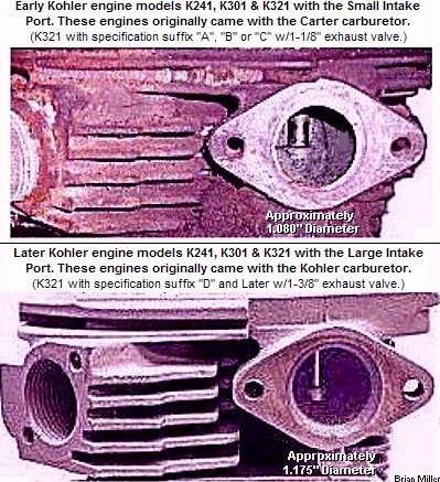 Remember, when enlarging the
ports, especially the intake port, make it the same size as the venturi in
the carburetor or an air restriction (bottle neck) will occur, and the engine
will not breath sufficiently at higher RPM. The exhaust port runner needs
to be about 22% smaller than the intake port.
Remember, when enlarging the
ports, especially the intake port, make it the same size as the venturi in
the carburetor or an air restriction (bottle neck) will occur, and the engine
will not breath sufficiently at higher RPM. The exhaust port runner needs
to be about 22% smaller than the intake port.
FYI - Regardless of what you've heard, running an engine without a muffler or some kind of exhaust system will NOT cause the exhaust valve to burn. This is an old mechanic's myth that got started many years ago when poor quality metal was used in the manufacturing of exhaust valves. Technology in metallurgy and quality of exhaust valves have advanced a lot in recent years.
Information About Valve Springs - [Top of Page]
The Reason Low-Pressure Valve Springs are Used in Most Small Engines Opposed to Much Stiffer Springs That's Used in Automotive Engines-
Most 4-cycle flathead and OHV (Over Head Valve) lawn and garden equipment small engines have a governor that controls and limits the engine's top speed and allows the engine to rev to around 3,200-3,600 RPM. The valve springs don't need to be very stiff at 3,200-3,600 RPM because the engine doesn't rev fast enough for. 1) the valves to float, and 2) the keepers/locks/collets to become dislodged, causing a valve to disconnect from the retainer. In an OHV engine, this is known as "dropping a valve." Which will likely destroy the engine. For most automotive engines on the other hand, they don't use a governor to limit the engine's RPM. Therefore, they require much stiffer valve springs, especially the OHV engines, so the engine will rev up faster, and to lessen the chance of "dropping a valve."
 NEVER Install Rusted Valve
Springs in an Engine!
NEVER Install Rusted Valve
Springs in an Engine!
Used valve springs rarely lose adequate pressure to open and close the valves at the RPM they are designed for. They can be reused as long as they're not rusted. Because the rust-pitted areas is a weak spot and when in operation and under pressure, the spring could break. Sometimes when out of an engine, and in storage [on the shelf], condensation will rust valve springs. When storing valve springs for a long period of time, submerge them in a container of lightweight oil or kerosene to prevent from rusting. YouTube link: Valve spring 8500 rpm.
Pulling Engines That Turn at High RPM or at open RPM -
If an engine is going to turn above 4,000 RPM, stiffer valve springs will need to be installed along with heavy-duty retainers. (And definitely make sure the flywheel is precision balanced or better yet, install a steel flywheel. along with a quality connecting rod that has an inserted bearing.) Stiffer valve springs reduce the chance of "valve float," which occurs at high RPM. ("For every action, there's an equal and opposite reaction." - Newton's third law of motion.) Valve float allows the engine to momentarily lose compression, cause fuel to spray out the carburetor and the engine will make a "hunt, hunt" sound. As a result, the engine will lose power, and as the weight of the sled is coming up on the tractor, the engine may not be able to recover.
If one is lucky enough to find some, they could use the inner spring of a high-performance automotive valve spring kit in a single cylinder engine. Stock keepers/locks/collets should work fine, too. By the way - valve keepers usually don't wear or get damaged because they don't rotate on the valve stem. To check yours, with a valve out of the engine, install a valve retainer or rotator on the valve, then the keepers, and then pull back hard on the retainer or rotator. If the retainer or rotator holds or squeezes the keepers tight in the groove, then they can be reused. Anyway, to reduce the chance of valve float, use dual springs along with stainless steel valves, hardened retainers and keepers when using a steel cam that has a lot of lift (more than .460" of lift). If using ordinary long lasting valves with dual springs, the head of the valve(s) (especially the exhaust valve) might become concaved over time because of the extreme pressure. And make sure that "coil bind" doesn't occur (when the spring become totally collapsed and the coils actually touch each other) when the valve is at full lift. Coil bind could break a good cast camshaft or even bend a steel one.
Using the Small Block Chevy Valves in a Kohler Engine -
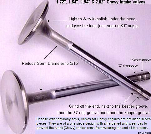 Small block Chevrolet V8 and certain Chevy V6 stock intake
valves will work in a K241-K341 Kohler engine with excellent results, even
with offset valve guides. The 1.72", 1.84", 1.92"
or 2.02" diameter intake valve can be used for the intake in a K241-K341
[pulling] engines. The 1.94" and 2.02" Chevy valves will work for the intake
in a 16hp/50.5 c.i. [pulling] engine. And despite what anybody says, valves
for Chevy engines are not made in two pieces. They are of a one piece design
with a hardened anti-wear cap to prevent the stock [Chevy] rocker arms from
wearing the end of the stems.
Small block Chevrolet V8 and certain Chevy V6 stock intake
valves will work in a K241-K341 Kohler engine with excellent results, even
with offset valve guides. The 1.72", 1.84", 1.92"
or 2.02" diameter intake valve can be used for the intake in a K241-K341
[pulling] engines. The 1.94" and 2.02" Chevy valves will work for the intake
in a 16hp/50.5 c.i. [pulling] engine. And despite what anybody says, valves
for Chevy engines are not made in two pieces. They are of a one piece design
with a hardened anti-wear cap to prevent the stock [Chevy] rocker arms from
wearing the end of the stems.
Stock intake valves works great as an exhaust valve in a pulling engine because the engine doesn't run long enough for the valve to burn or warp.
The valve stem will need to be shortened next to the keeper groove (make the overall length the same as Kohler valves, which is 4.635".), and the oil seal groove becomes the keeper groove. Being the Chevy valve stem is 11/32" in diameter, the valve guide(s) will need to be enlarged with an 11/32" reamer so the valve stems will have correct clearance.
The Chevy valve head will also need to be lightened and the face (and seat) should be ground at a 30º angle for the intake (for maximum air flow), and 45º for the exhaust. And either the Chevy retainers can be used or stock Kohler retainers can be used with the Chevy valve. But the Chevy keepers/locks must be used because of the larger diameter valve stem. The Chevy retainer will need to be turned down in a metal lathe to fit the smaller aftermarket valve springs that's made for Kohler pulling engines. Don't try use Chevy valve springs in a Kohler engine! They're way too stiff and much too difficult to install in a Kohler engine. Actually, they're almost impossible to compress for installation in a Kohler engine.
Remember to do this when installing bigger/oversize valves -
 When
installing larger valves, the tapered area on the engine block around each
valve must be ground away for full airflow into and out of the combustion
chamber. The area just outside of the valve seats next to the piston area
(the area where the valves are angled down into the block) needs to be ground
away also so the engine can have full air flow in and out of the cylinder.
This is very important because if it isn't opened up there, it'll starve
the engine for air/fuel. To check this area for adequate clearance, with
the head removed, rotate the engine so each valve is fully opened, then insert
a wooden dowel or soft aluminum rod (to keep from scratching the valve face
and seat) that has the same diameter of the lift of the cam to use as a plug
gauge. Grind the tapered area around the valves enough so with the valves
installed, you can fit a soft metal (aluminum rod) between the valve face
and seat with the valves at full lift. This is how you get full airflow into
and out of the combustion chamber. With the metal ground away, the rod should
fit snug under the valve head and seat all the way around each valve. If
the plug gauge doesn't fit, the metal on the block just outside each valve
seat needs to be ground away, especially toward the piston. Be extremely
careful not to let the grounding stone touch the finished seats though! (And
always wear
eye protection whenever working with metal!)
When
installing larger valves, the tapered area on the engine block around each
valve must be ground away for full airflow into and out of the combustion
chamber. The area just outside of the valve seats next to the piston area
(the area where the valves are angled down into the block) needs to be ground
away also so the engine can have full air flow in and out of the cylinder.
This is very important because if it isn't opened up there, it'll starve
the engine for air/fuel. To check this area for adequate clearance, with
the head removed, rotate the engine so each valve is fully opened, then insert
a wooden dowel or soft aluminum rod (to keep from scratching the valve face
and seat) that has the same diameter of the lift of the cam to use as a plug
gauge. Grind the tapered area around the valves enough so with the valves
installed, you can fit a soft metal (aluminum rod) between the valve face
and seat with the valves at full lift. This is how you get full airflow into
and out of the combustion chamber. With the metal ground away, the rod should
fit snug under the valve head and seat all the way around each valve. If
the plug gauge doesn't fit, the metal on the block just outside each valve
seat needs to be ground away, especially toward the piston. Be extremely
careful not to let the grounding stone touch the finished seats though! (And
always wear
eye protection whenever working with metal!)
If you're concerned about doing the above È will decrease the compression ratio, well, it will somewhat. But, by doing so, it'll allow the engine to draw in much more air, producing more compression. In return, it'll produce more power and RPM. I know, we've done this many times with excellent results.
And the only way I found to grind this area of the block is to use a 1/4" capacity pneumatic die grinder with a 1" diameter rounded end stone. To keep the stone from touching the valve seat, I rest the side of my right hand on the top of the block (I'm right handed) and slowly and very carefully grind away the metal.
Information About Valve Guides - [Top of Page]
What Causes a Small Engine to Make an Erratic "Pop" Sound Out the Exhaust at Idle Speed? (Added 3/22/21)
An engine misfire at idle speed may be caused by an excessively worn valve guide, especially the exhaust, because carbon deposits can sometimes wear away at inside of the guide. A worn guide will cause the valve to "dance around" upon closing and not fully close or not make full contact with the seat at times. When the fuel ignites the moment the valve is not fully closing, this will momentarily send the combustion out through a "wedge" between the valve and seat instead of containing it within the combustion chamber, which will make an erratic popping sound out the exhaust. An excessively worn intake valve guide may make a popping sound out through the carburetor at idle speed. To check for excessive worn or looseness of the valve guides, remove the cylinder head, and with each valve at its highest lift, use your hand & try to wiggle them around. But then again, a slight misfire, especially at higher RPM, can be caused by a faulty ignition condenser.
Replacing or Installing New Valve Guides -
It requires special tooling to install replacement valve guides for precision and accuracy. To accurately bore out a valve guide, a special-made 60º tapered pilot needs to be placed inside the valve seat to guide the cutting tool straight through the guide. Otherwise, it will be bored crooked. If an integrated valve guide hole is drilled crooked due to a worn guide, the block may be ruined. And although Briggs & Stratton offers valve guides that can be installed in virtually small engine block, it's actually better, more accurate and probably cost less to have a reputable automotive machine shop install universal thin-wall bronze sleeve valve guides in your block. The thin-wall bronze sleeve valve guides can be installed in existing OEM pressed-in valve guides, too. Thin-wall bronze sleeve valve guides come in various sizes and this is the same type of guides that most automotive machine shops install in automotive OHV cylinder heads and flathead engines nowadays. Because the pressed-in replacement valve guides is old school technology. If you decide to have universal thin-wall bronze sleeve valve guides installed in your flathead or OHV small engine, you will need take the valves with the block or head so the person who installs the guides can measure the valve stems so the guides will have the correct clearance. I've had this done on my own personal engines, and to many of my customer's engine rebuilds and it works great.
FYI: The alternative to installing new replacement OEM-type valve guide(s) is to have the old [worn] guide(s) reamed for installation of thin-wall bronze sleeves/liners (bushings), which can be installed by an experienced and reputable automotive machine shop. Thin-wall bronze valve guides are a low-cost and actually works better than replacing the OEM guide in most engines. Bronze lasts longer than cast iron guides because it is harder material and it retains more oil for better lubrication of the valve stem. Installing CLASSIC Bronze-Liners
There are two ways to measure the amount of wear in valve guides. One way is with a dial indicator. The other way is with an "go/no go gauge" and a micrometer. It's best to have a local machine shop do the measuring because they have the right tools and they're experienced with such things.
How to Remove and Install Pressed-In Cast Iron Valve Guides in a Cast Iron Block Kohler Engine:
Acquire a 1/2" diameter x 5"
long grade 8 bolt. Machine the threads down to .300" so it will become a
pilot to fit inside the valve guide. This will
be the driver tool.
FYI: The alternative to installing new replacement OEM-type valve guide(s) is to have the old [worn] guide(s) reamed for installation of thin-wall bronze sleeves/liners (bushings), which can be installed by an experienced and reputable automotive machine shop. Thin-wall bronze valve guides are a low-cost and actually works better than replacing the OEM guide in most engines. Bronze lasts longer than cast iron guides because it is harder material and it retains more oil for better lubrication of the valve stem. Installing CLASSIC Bronze-Liners
Installing Offset Valve Guides -

 The
best way to gain more power and torque from any engine is to have a smaller
combustion chamber to increase the compression ratio. On a flathead (valves
in block) engine, the way to do this is by moving the valves closer to each
other and closer to the piston with the use of offset valve guides. Machining
for oversized valves must be installed in order to do this. Stock valves
cannot be used with offset guides because the offset guides will move a portion
of the valve head off the seat (it'll have a crescent moon shape). Valve
guides for Kohler engines can be made with the hole offset at any distance
from center, but the most common offset is .085".
The
best way to gain more power and torque from any engine is to have a smaller
combustion chamber to increase the compression ratio. On a flathead (valves
in block) engine, the way to do this is by moving the valves closer to each
other and closer to the piston with the use of offset valve guides. Machining
for oversized valves must be installed in order to do this. Stock valves
cannot be used with offset guides because the offset guides will move a portion
of the valve head off the seat (it'll have a crescent moon shape). Valve
guides for Kohler engines can be made with the hole offset at any distance
from center, but the most common offset is .085".
For the K241, K301 and early model K321 Kohler engines with the OEM centered valve guide and valve seat removed, a 1.375" [OEM intake] valve can be used in the exhaust hole. But with the seat removed and a .085" offset guide installed, a minimum 1.545" oversized valve will need to be used, with a maximum 1.420" inside diameter seat machined into the block. (1.250" [diameter of counterbore] + .170" [.085" x 2] = 1.420" [seat inside diameter] + .125" [added for overall valve head diameter] = 1.545".) For the intake valve with a .085" offset guide with no valve seat insert (seat machined directly in the block), a maximum of 1.700" oversized valve can be used.
And for the later K321 or all K341 Kohler engines with the original 1.375" diameter exhaust valve and the OEM centered valve guide with the valve seat removed, a 1.600" oversize valve can be used in the exhaust (or intake) hole. But with the seat removed and a .085" offset guide installed, a minimum 1.795" oversized valve will need to be used, with a maximum 1.670" inside diameter seat machined into the block. (1.500" [diameter of counterbore] + .170" [.085" x 2] = 1.670" [seat inside diameter] + .125" [added for overall valve head diameter] = 1.795".) But for the intake valve with a .085" offset guide, a maximum of 2.000" oversized valve can be used.
About Titanium Valves -
Titanium valves with too large of a head and too long of stem can be machined smaller for use in a Kohler engine, but titanium is extremely hard material and almost impossible to machine in a metal lathe even with carbon bits, which is the hardest available. I've tried to machine titanium valves before with no luck. They need to be ground (machined) with a metal grinder instead.
Installation of new valve guides usually doesn't require new valves. Although the valves will need to be reground so they will seat better. And to remove the guides, first remove the valves. Then use a long 5/16" grade 8 bolt with a nut threaded on it and a heavy hammer to drive the guides out and into the valve spring compartment. Install new guides by driving them in with a hammer until they are flush with the port. The offset guides may need to be enlarged with a 5/16" reamer so the valve stems will have correct clearance. There are 3 ways to install new valve guides:
Bronze is hard material and it retains oil because it's porous. Go here to learn more about bronze valve guides: K-line Interrupted Spiral Guide-Liners. To help the guides and valve stems last longer, drill a small (1/8") hole crossways through the lower part of each guide in the valve spring compartment so the crankcase oil will help keep the valve stems and guide well lubricated and cool. This will reduce stem-to-guide friction (wear) and it'll help promote smooth valve action, which will help increase horsepower slightly and longevity of the guide.
To remove the valve guides from the K241-K341 Kohler engines, drive them out into the valve spring compartment with a 5/16" diameter grade 8 bolt with a nut threaded on the bolt and a big hammer. Also, after many years of use, some guides can be very stubborn to remove, especially the exhaust one. So instead of removing the old guides from an engine with stock valves, have them reamed to accept a thin-wall bronze sleeve/liner. Besides, all new OEM guides needs to be reamed for the valve stem to fit anyway. So why not have a bronze liner installed instead? FYI: The alternative to installing new replacement OEM-type valve guide(s) is to have the old [worn] guide(s) reamed for installation of thin-wall bronze sleeves/liners (bushings), which can be installed by an experienced and reputable automotive machine shop. Thin-wall bronze valve guides are a low-cost and actually works better than replacing the OEM guide in most engines. Bronze lasts longer than cast iron guides because it is harder material and it retains more oil for better lubrication of the valve stem. Installing CLASSIC Bronze-Liners
When thin-wall bronze valve guide sleeves/liners are installed, first, the valve guide is reamed the same outside diameter as the liner. Then the liner is inserted in the guide, and an air-operated valve guide driver is used to expand the liner in the guide so it'll have the correct clearance for the valve stem.
To bore the offset center hole in a guide, drill the hole in the guide approximately .085" offcenter with the guide firmly clamped in a super spacer (with a self-centering 3-jaw chuck) that's fastened on the table of a vertical milling machine. When drilling bronze, use a non-oily lubricant, such as brake cleaner.
 How
to locate where to machine the cylinder head for the valves.
How
to locate where to machine the cylinder head for the valves.
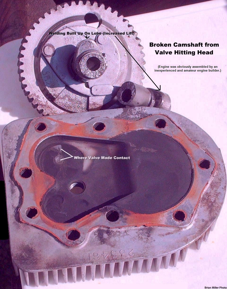
How to check for correct valve clearance between the valves and cylinder head.
 If the crankshaft rotates freely
after 360º, remove the head and use the depth gauge on a dial or digital
vernier
caliper to determine the thickness of the clay. The clay should have
a minimum thickness of about .070".
If the crankshaft rotates freely
after 360º, remove the head and use the depth gauge on a dial or digital
vernier
caliper to determine the thickness of the clay. The clay should have
a minimum thickness of about .070".
How to make your own modeling clay (Play-Doh):
Directions: Thoroughly mix flour, salt and cream of tartar or alum. Boil liquids together. Pour in dry ingredients and stir together. Knead and add flour as needed. [Return To Previous Paragraph, Section or Website]
FYI - One valve I found is an exhaust valve made for a Wisconsin engine. It's a Perfect Circle part #211-1832. It has a 1.590" diameter head and 5/16" diameter stem. Overall length is 4.865". But Kohler valves are 4.635" in overall length. This means the stem will need to be shortened .230" and a new keeper groove will need to be machined. Check at a local auto parts supply store for this valve. They can usually get any size or type of valve you want.

 If one is extremely careful, bigger/oversize valves
can be installed using a pneumatic (air-operated) 1/4" capacity
pneumatic die grinder with an ordinary grinding stone and
an electric valve seat grinder. There's no need to install valve seat inserts
either. Just cut or grind the new seats directly into the cast iron block.
For best flow and compression, the high point of the seat needs to be even
with the deck of the block. If the seat is made too deep, valuable flow and
compression will be lost! Most blocks can be decked to regain the compression,
though. (If rules allow it.) (And always wear
eye protection whenever working with metal!)
If one is extremely careful, bigger/oversize valves
can be installed using a pneumatic (air-operated) 1/4" capacity
pneumatic die grinder with an ordinary grinding stone and
an electric valve seat grinder. There's no need to install valve seat inserts
either. Just cut or grind the new seats directly into the cast iron block.
For best flow and compression, the high point of the seat needs to be even
with the deck of the block. If the seat is made too deep, valuable flow and
compression will be lost! Most blocks can be decked to regain the compression,
though. (If rules allow it.) (And always wear
eye protection whenever working with metal!)
For best valve flow, cut or grind the intake valve face and seat at a 30º angle, and the exhaust valve face and seat at a 45º angle. Give the intake seat about a .030" width, and the exhaust seat about a .060" width. Make the valve face mating surface near the edge of the valve, too.
What is Port and Polish (or Porting and Polishing) of an Engine? - [Top of Page]
 "Porting" is when the intake and exhaust port runners in a
flathead engine block or OHV (Over Head Valve) cylinder head are made larger
in volume so more air/fuel can enter the combustion chamber and the exhaust
gases can exit quicker so the engine will produce higher compression pressures
which results in more power and torque at higher RPM.
"Porting" is when the intake and exhaust port runners in a
flathead engine block or OHV (Over Head Valve) cylinder head are made larger
in volume so more air/fuel can enter the combustion chamber and the exhaust
gases can exit quicker so the engine will produce higher compression pressures
which results in more power and torque at higher RPM.
"Polishing" is when the ports are made smooth. Many years ago, most high-performance engine builders thought that by making the intake port and intake manifold (or carburetor extension, spacer, intake tube, stand-off, or whatever they may be called by garden tractor pullers), smooth and polished, this would help the engine to produce more power and torque. Which in theory makes sense. But in reality and in recent dyno tests, the intake passageway shouldn't be smooth or polished. If enlarged (for more airflow), but made with a rough surface, this will create turbulence in the port. The turbulence will cause the incoming air to atomize with the fuel vapors more thoroughly, which will help the engine produce much more horsepower and torque at high RPM or at open RPM. The exhaust port runner and header pipe on the other hand, should be smooth and polished, so the spent exhaust gases can exit the combustion chamber quickly and smoothly.
An Easy and Sure Way to Determine the Port Size and Flowing the Ports -
When enlarging the intake and exhaust port runners to move more air in and out of the combustion chamber so the engine can produce more power, and to determine the correct size of each port, for the intake port, make a couple of "plug gauges" from a 1.000" diameter fender washer, which can be mounted on a long bolt for use as a handle, for a carburetor with a maximum 1" venturi (for a Stock-Altered pulling engine), or a 1.200" diameter fender washer to match a 1.200" carburetor (for a 16hp Missouri Hot-Stock and 16hp Missouri Super-Stock pulling engines). And use a 1.000" washer for the exhaust port in a 10-14hp Kohler engine.
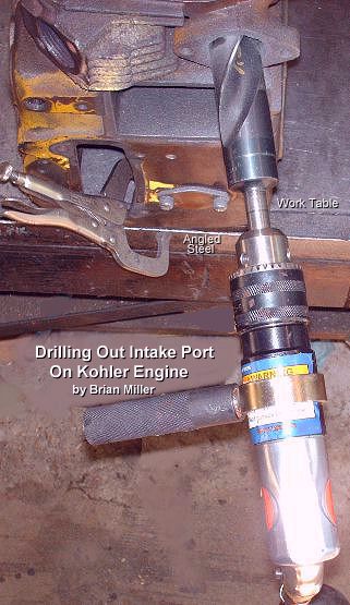
 For best engine
performance, the intake port runner should be enlarged to match the diameter
of the carburetor's bore or venturi. To enlarge the ports or "port out" in
a flathead engine block or OHV cylinder head, a
pneumatic die grinder with a large, long pointed stone
could be used, but this method is VERY time consuming and tiresome. It takes
about 5-6 hours of labor with a quality-made air die grinder, quality-made
grinding stone and a high capacity air compressor/tank.
For best engine
performance, the intake port runner should be enlarged to match the diameter
of the carburetor's bore or venturi. To enlarge the ports or "port out" in
a flathead engine block or OHV cylinder head, a
pneumatic die grinder with a large, long pointed stone
could be used, but this method is VERY time consuming and tiresome. It takes
about 5-6 hours of labor with a quality-made air die grinder, quality-made
grinding stone and a high capacity air compressor/tank.
 But instead of using the die
grinder, a 1/2" capacity
pneumatic air drill with a large high speed steel drill
bit and high capacity air compressor can be used for much faster and accurate
results to enlarge the port(s). NOTE: Pneumatic air drills draw a lot
of air volume when in use. So an air compressor with a minimum 60 gallon
storage tank and good size pump will need to be used to supply adequate air
to keep up with the demand of the air drill.
But instead of using the die
grinder, a 1/2" capacity
pneumatic air drill with a large high speed steel drill
bit and high capacity air compressor can be used for much faster and accurate
results to enlarge the port(s). NOTE: Pneumatic air drills draw a lot
of air volume when in use. So an air compressor with a minimum 60 gallon
storage tank and good size pump will need to be used to supply adequate air
to keep up with the demand of the air drill.
For the K241, K301 and early model K321 blocks (with the 1-1/8" exhaust valve), use the pneumatic air drill with a [high quality and sharpened] 1-1/16" or 27mm (which is close to 1.07") drill bit to enlarge the intake port to match the #26 carburetor with a 1.07" throttle bore that have the venturi bored-out. This should take about 30 minutes to complete. Because there's more material (metal) to remove. And for a later model K321 (with the 1-3/8" exhaust valve), M14, K341 and M16 blocks, use a 1-3/16" or 30mm (which is close to 1.2") drill bit to match the #30 carburetor with a 1.2" throttle bore that have the venturi bored-out. This process should take about 10 minutes to complete. Because there's less material (metal) to remove. Apply WD-40 frequently inside the port to aid in quicker cutting of the drilling process. (And always wear eye protection whenever working with metal!) The intake port doesn't need to be bigger than the carburetor's straight-through throttle bore (with the venturi bored-out) that's going to be used on the engine.
Fabricate a plug gauge made with a flat washer of the appropriate diameter fastened on a long bolt with two jam nuts to serve as a handle. After the port is "drilled out" or enlarged, if there's any high spots, use a 1/4" capacity pneumatic die grinder with a 1" diameter pointed stone for a smooth final finish. When grinding the port, feel inside the port with your finger for smoothness.
When facing the intake port, position the air drill so the shank of the drill bit is aimed slightly downward and slightly angled to the right in relation to the engine block. This will make for the best air flow through the port and into the combustion chamber. Afterwards, the drilling process should leave the port straight and smooth to the touch. If there are a few rough spots, they can be smoothed with a die grinder/stone. Don't use an electric drill, even a heavy duty one, to drill out the ports in an engine! A very large drill bit will likely to "catch" or get "hung up" abruptly in the cast iron during the drilling process and this could cause the reduction gears in the drill to strip out and break. Pneumatic drills have no gears, just an air turbine. Therefore, if/when the bit catches in the port, there's nothing break in the drill.
Degree of the Intake Center Line -
The intake centerline angles that I use when I port a K241-K341 Kohler engine are 4º down and 4º to the right when standing to the side of the block. If an engine has hardened exhaust valve seat(s), unleaded gasoline has no effect on the wear of the seat(s). In fact, all engines built nowadays or since unleaded gas was first introduced have hardened exhaust valve seats. Valves are unaffected by unleaded gas. Also, unleaded gas helps to keep the combustion chamber free of carbon deposit buildup.
Information about Valve Lifters (Tappets) - [Top of Page]
About a Worn Lifter Adjuster Head and Face -
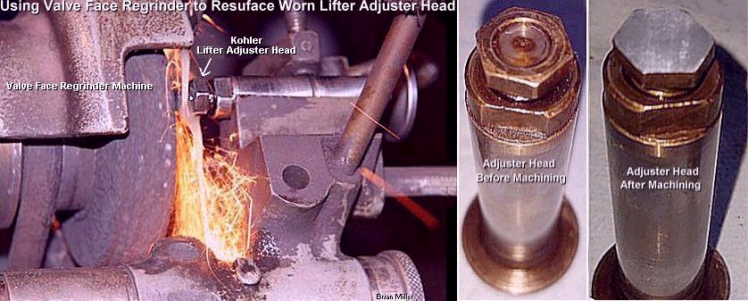
 When adjustable Kohler lifters wear,
sometimes the center of the adjuster head will wear or become concaved, which
will affect valve adjustment if not made perfectly flat again. The head will
need to reground on a valve grinding machine until it's perfectly flat again.
(And always wear
eye protection whenever working with metal!)
When adjustable Kohler lifters wear,
sometimes the center of the adjuster head will wear or become concaved, which
will affect valve adjustment if not made perfectly flat again. The head will
need to reground on a valve grinding machine until it's perfectly flat again.
(And always wear
eye protection whenever working with metal!)
When new flat tappets or lifters are manufactured, the center of the lifter face (the part that makes contact with the lobe on the cam) is slightly raised (approximately .001"). The lifter sits slightly off-center of the cam lobe so when the valve opens, the lobe rotates the lifter slightly to prevent wear to either part. Otherwise, if the lobe is centered with the lifter, the lobe will scrape the lifter when the valve opens, causing excessive wear to both the lifter and lobe in a short time. If you need to replace a worn lifter (and undoubtedly the camshaft, too), the best thing to do is acquire a good used lifter (I have a bunch of good used OEM Kohler lifters in stock) or purchase a new one. It is almost impossible to "reface" a lifter because they're made of extremely hardened steel. A good used lifter can be successfully reused with a new or used camshaft without wearing the cam lobe. What needs to be done to prevent wear to the lobe is roughen the face of the lifter with 600 grit sandpaper until all the shiny surface is gone. This will provide a new wear pattern for the lifter and lobe. For break-in of the lifter and lobe, use SAE 30 weight conventional (petroleum-based) motor oil with high zinc content to provide a protective film as the parts wear into each other, producing a hardened surface wear pattern. If a lifter face is pitted with rust, it will need to be replaced with either a good used lifter or a new one. And if the cam lobe(s) are worn, then either replace it with another good used camshaft, or for a K241-K341 Kohler camshaft, the lobes can be welded up and professionally reground to turn it into a performance camshaft.
Reusing Flat Base Lifters/Tappets - (Added 6/7/24)
 The
base or face (the part that makes contact with the cam lobe) on all new lifters
(or tappets, as they're sometimes called) have marks for a cross-hatch pattern.
Therefore, if the base/face on a used lifter isn't worn, it can be reused
by rubbing the base/face (by hand) on 400 grit sandpaper on a hard, flat
surface to give it new marks for a cross-hatch pattern. Be sure to retain
the 1º
convex (curved) shape to match the 1º angle on the
nose or toe of the cam lobe. Making new cross-hatch marks will allow the
lifter to "grip" the cam lobe upon every lift so the lifter will rotate slightly
(prevent scraping), creating a new wear pattern and prevent wear to both
the lifter and lobe.
The
base or face (the part that makes contact with the cam lobe) on all new lifters
(or tappets, as they're sometimes called) have marks for a cross-hatch pattern.
Therefore, if the base/face on a used lifter isn't worn, it can be reused
by rubbing the base/face (by hand) on 400 grit sandpaper on a hard, flat
surface to give it new marks for a cross-hatch pattern. Be sure to retain
the 1º
convex (curved) shape to match the 1º angle on the
nose or toe of the cam lobe. Making new cross-hatch marks will allow the
lifter to "grip" the cam lobe upon every lift so the lifter will rotate slightly
(prevent scraping), creating a new wear pattern and prevent wear to both
the lifter and lobe.
How to Use Ordinary Hydraulic Lifters in a High-Performance/Open RPM Engine -
 When pulling (or racing) virtually
any open RPM competition garden pulling tractor engine (such as Kohler Command)
or automotive engine with hydraulic flat bottom or roller lifters, to prevent
from using
anti-pump up lifters, ordinary stock lifters can be used
instead. To prevent ordinary stock lifters from "pumping up" with oil at
open RPM, which may cause the valves to momentarily not fully close, simply
set the valve clearances at zero lash with no preload in the lifter. By doing
this, the lifters will always be pumped up, allowing the valves to fully
close at open RPM, and preventing an erratic or momentary misfire and backfire
(through the intake or out the exhaust).
When pulling (or racing) virtually
any open RPM competition garden pulling tractor engine (such as Kohler Command)
or automotive engine with hydraulic flat bottom or roller lifters, to prevent
from using
anti-pump up lifters, ordinary stock lifters can be used
instead. To prevent ordinary stock lifters from "pumping up" with oil at
open RPM, which may cause the valves to momentarily not fully close, simply
set the valve clearances at zero lash with no preload in the lifter. By doing
this, the lifters will always be pumped up, allowing the valves to fully
close at open RPM, and preventing an erratic or momentary misfire and backfire
(through the intake or out the exhaust).
Information about the Camshaft and How to Degree in a Steel Cam - [Top of Page]
 The most important part of any
high-performance engine is the camshaft. It's the heart of the engine. Simply
put, the cam tells the valves what to do, when to do it and for how long.
To be truly competitive on the track, a high-performance engine really needs
the latest and updated cam that's available. Installation of a special camshaft
is important if increased performance is to be obtained. Performance camshafts
lift the valves higher and hold them open longer in relation to piston travel
than stock cams. The increased lift is known as "valve lift" and when the
valves stay open longer, this is known as "duration." Cams with much more
lift and especially more duration than a factory stock cam is considered
a "performance cam."
The most important part of any
high-performance engine is the camshaft. It's the heart of the engine. Simply
put, the cam tells the valves what to do, when to do it and for how long.
To be truly competitive on the track, a high-performance engine really needs
the latest and updated cam that's available. Installation of a special camshaft
is important if increased performance is to be obtained. Performance camshafts
lift the valves higher and hold them open longer in relation to piston travel
than stock cams. The increased lift is known as "valve lift" and when the
valves stay open longer, this is known as "duration." Cams with much more
lift and especially more duration than a factory stock cam is considered
a "performance cam."
The rule of thumb for any high performance engine is, the higher the rpm, the more valve lift and duration the cam lobes needs to have so the engine will produce more power. The increased lift allows for more air to enter and exit the combustion chamber at higher rpm, and the increased duration traps more air in the combustion chamber at higher rpm to build up the compression. On the engine dyno, with a factory stock cam, the engine will make power up to around 3,600 rpm, then "flat line" or fail to produce more power after that.
How a high-performance cam with increased lift and duration help the engine produce more power -
High performance cam technology is always advancing! What works for one engine won't necessarily work for another. Therefore, if you're wondering which cam profile will work best for your particular engine, it really depends on how many RPM the engine is going to turn. If it's going be governed at 4,000 RPM, then perhaps an K361 cam will work fine. But if it's going to turn faster, then a cam that's designed for a Stock-Altered or Super-Stock engine should be used. It's best to talk to a professional cam grinder person to determine which cam would benefit your engine best so it'll produce maximum RPM, power and torque.
Air is very flexible. It can be compressed as well as it can be expanded. When an engine has a long duration cam, with the cylinder head off, as the crankshaft is slowly rotated by hand, you may notice that before the piston reaches TDC (Top Dead Center) or BDC (Bottom Dead Center), the valves stay open longer and doesn't fully close until the piston is a good ways up or down in the cylinder. This is called "duration." With an OEM stock cam or short duration cam, the valves will become fully closed when the piston is at or close to TDC or BDC. Anyway, with a long duration cam, when an engine revs at high RPM or at open RPM, air doesn't have time to exit out through the valves, so it "compresses" and becomes trapped within the combustion chamber. In this way, the piston can draw more air (and fuel mixture) into the combustion chamber through the intake valve. The engine is able to build up more compression at higher RPM with a long duration cam so it will produce more power. In addition, a larger portion of the burned gases will be expelled from the combustion chamber through the exhaust valve. This is why most high-performance automotive engines with a long duration cam idle "radically" or with a low tone, loping/thumping sound, and single cylinder pulling engines with a long duration cam and an open header pipe have a bellowing "BOOM, BOOM" sound out the exhaust. That's air the piston is pushing out past the exhaust valve before the valve can fully close. The reason it makes the BOOM, BOOM sound is because air is moving faster than the speed of sound, which breaks the sound barrier.
 Measuring the Overall Length
of a Kohler Camshaft -
Measuring the Overall Length
of a Kohler Camshaft -
Use the depth gauge on a dial or digital vernier caliper to accurately determine the exact overall length of a K241, M10-K341, M16 and K361 camshaft. The length should measure between 5.801" - 5.806". When installed in the engine and for the correct amount of end-play/clearance, most cams require a .005" and .010" shim to allow for the .005" to .010" factory-specified end-play/clearance. If a cam measures too short, then it is worn narrow on the flywheel end, or the inside of the block is worn wide (on the flywheel end) so the cam will have excessive amount of end-play/clearance. If a cam is worn short, or if the block is worn wide, being the cam has angled gear teeth that push it forward in the block when in operation, add the shims/thrust washers/spacers on the flywheel end of the cam. This should place the cam in perfect timing with the crankshaft. If excessive shims/thrust washers/spacers are added to the PTO end of the block, this will advance the valve timing so much that the cam will not be in perfect timing with the crankshaft, and the engine will not produce full power and it will run sluggish.
 Also,
cylinder head clearance, improved
carburetion, larger valves and stiffer valve springs
are a must in order to take full advantage of a bigger cam. And always
use the 1.280" diameter wide base lifters with a cam that has at least .400"
of lift despite the duration. Use of the right cam and precise valve timing
can help an engine come to life and scream down the track!
Also,
cylinder head clearance, improved
carburetion, larger valves and stiffer valve springs
are a must in order to take full advantage of a bigger cam. And always
use the 1.280" diameter wide base lifters with a cam that has at least .400"
of lift despite the duration. Use of the right cam and precise valve timing
can help an engine come to life and scream down the track!
 When using a billet steel camshaft
with minimum .575" of lift and dual valve springs, it's best to use a billet
steel cam gear also. Because if a cast iron gear is used, the gear teeth
could break when the cam comes around right when lift occurs, which will
likely break the gear teeth on the crankshaft, too. Also, the "shrapnel"
of loose broken gear teeth flying around in the crankcase could become lodged
between other moving parts, destroying them as well.
When using a billet steel camshaft
with minimum .575" of lift and dual valve springs, it's best to use a billet
steel cam gear also. Because if a cast iron gear is used, the gear teeth
could break when the cam comes around right when lift occurs, which will
likely break the gear teeth on the crankshaft, too. Also, the "shrapnel"
of loose broken gear teeth flying around in the crankcase could become lodged
between other moving parts, destroying them as well.
The correct installation of the camshaft is very important for full power and torque. The camshaft is the heart of your engine and if it isn�t installed properly, the whole engine will run sluggish. Camshaft degreeing is the one most important thing that can be done to an engine. If the camshaft isn't degreed in, odds are it will usually be too far advanced or retarded. I highly recommend that you properly degree your camshaft. Step-by-step method of how to degree your camshaft is listed below. If your camshaft can move back and forth in your engine, you are losing power. When your camshaft moves forward, your ignition timing becomes retarded, which makes your engine run sluggish.
BE AWARE! Lifts up to .432"
can safely be put on the Kohler cast cam. A Kohler cast iron camshaft with
more lift than .432" lift that has both lobes welded-up and reground for
more lift and duration is not expected to live long with stiffer-than-stock
valve springs. The more lift a cast cam has, the more likely it is to break.
It's only a matter of time. They break next to the gear. The reason they
break is because the support pin flexes under load (valve lift), and cast
iron doesn't. That's why if a cast cam is used, it's best to use a support
pin made of hardened steel.
When rebuilding a Kohler
engine or installing another [cast] camshaft, check the cam pin for wear.
If it's worn, this will allow the cam to "wobble around" at high engine RPM
resulting in erratic valve action, and it'll cause the ignition timing to
be very erratic, which will cause the engine to run erratic and lose power.
A cam running on a worn pin will even make the engine "pop" and backfire
out the exhaust at high RPM.
The OEM cast iron camshaft in the K90-K361 Kohler engines is held in place by a single long pin that goes in from the flywheel end of the block, through the cam and is wedged in the PTO side of the block. To remove it, use a long, hardened 3/8" diameter (for the K141, K160/K161 K181, L161, L181, M8 engines), 7/16" diameter (for the K241-K361 engines) bolt or steel rod and a medium size hammer, and drive it out from the PTO side of the block. It comes out on the flywheel side. Replacement is in the reverse order of removal. Be sure to reset the valve clearances after the new pin is installed. As the cam pin is driven out, be sure that the shim(s) (very flat washers) that's on the end of the cam towards the flywheel end don't fall out of place.
When using a cast cam in an engine that runs at open RPM, be sure to install heavier-than-stock valve springs to prevent valve float at high RPM. And make sure to use high zinc oil, not a multi-weight for newer engines. Without the zinc, it will wear the lobes. High zinc examples are: Delvac, Cen-Pe-Co, Amsoil Dominator, Red Line, Brad Penn, Rotella, Joe Gibbs, and others. Just check it out before you buy.
How a Long Duration Camshaft Works -
An engine that has a stock camshaft and when it is at an idle speed, about 95% of the air that enters the engine becomes trapped within the combustion chamber. This does not change as engine speed increases. But with a long duration cam that has "humped-up" lobes, at idle speed, some of the air that enters the combustion chamber, and being the valves stay open longer, exits through the intake and exhaust valves. This is why engines with a high-performance camshaft have a rough idle. The more duration a cam has, the rougher or more radical the engine will idle. Anyway, as engine speed increases, and being air can be compressed as well as it can be expanded, air will become trapped within the combustion chamber and can't be pushed back out into the carburetor and out the exhaust. The "trapping of air" builds up air pressure within the combustion chamber, which increases the compression pressure, resulting in a higher compression engine. Thus, allowing the engine to produce more power at higher RPM. The faster an engine revs up, the more air will become trapped in the combustion chamber. This is also why engines with a high-performance/long duration camshaft runs smooth as engine speed increases.
Have you ever noticed that when the piston is on the exhaust stroke, how each valve is slightly open? Well, that's called valve overlap. It's normal on all camshafts. It scavenges the exhaust gases from the combustion chamber and creates more vacuum for the incoming air/fuel. It happens only when the piston is on the exhaust stroke. And both valves are fully closed on the compression stroke. The more overlap a cam has, the rougher or "lopier" the engine will idle. This is why race cars idle so rough, and the Briggs & Stratton flathead opposed twin cylinder engines have a "lopey" idle.
Sometimes when using a high performance/long duration camshaft, regardless if the engine has a stock or modified carburetor, if the engine idles for a long period of time, it may run rich on fuel at a slow idle speed. What causes this is with a long duration cam, intake vacuum is low and with a single cylinder engine, being the valves stay open longer, excess fuel builds up in the carburetor and/or intake tube. All engines with a long duration camshaft have lower than normal vacuum at slow idle. The longer the duration a cam has, the lower the vacuum. What causes excess fuel to build up in the intake is the long duration of the cam lobes holds the [intake] valve open longer, and at slow idle, pressure of the piston moving upward in the cylinder blows some of the air/fuel back into the carburetor and/or intake tube. And as the engine is accelerated, raw unburned fuel (methanol) black smoke (gas) will blow out the exhaust pipe until the fuel is cleared out of the carburetor and/or intake tube. With the engine running well above idle, air becomes trapped within the combustion chamber and the piston don't have time to push any air/fuel back into the carburetor and/or intake tube. This happens with gasoline, E85 or methanol fuels, and there's nothing that can be done about it. It's the nature of the long duration camshaft. Some might think when this happens that there's something wrong with the carburetor, and nothing can be done to the idle fuel passageway to prevent this. Just make a simple adjustment with the idle air/fuel mixture screw, set the engine at a fast idle and don't allow the engine to idle for a long period of time. [Return To Previous Paragraph, Section or Website]
How to Install a High Performance Billet Steel Camshaft That Require Two Separate Support Pins in a Kohler 10-16hp Engine - [Top of Page]
This information is for stroker competition pulling engines (engines with a longer than stock stroke) with the OEM Kohler bearing plate. A maximum of 3.500" stroker crankshaft can be used with the pin-through type of cam. For a longer stroke, the two-pin billet steel cam that's ground thin between the lobes must be used. The parts required are: two 1/4-20 UNC x 1/4" length Allen set screws, one 1/4-20 UNC x 1/2" length grade 8 bolt, one 1/4' I.D. split lock washer, a wide, flat steel washer with a 1/2" center hole, and one OEM Kohler camshaft pin (in good condition, of course).
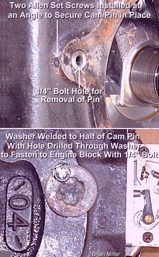
 Enlarge the
[tapered] camshaft pin hole in the PTO end of the block exactly to .500".
Enlarge the
[tapered] camshaft pin hole in the PTO end of the block exactly to .500".
Installing Needle Bearings in a Kohler Block for a High Performance Camshaft -
 To install needle bearings in a K241-K341
Kohler block for a high performance camshaft that will accept them, the holes
for the cam pin will need to be precision bored (enlarged) exactly dead center
to .6875" (11/16") on the table of a milling machine. The exact dead center
of the holes are found by using a
centering indicator. If the holes are bored off-center
just a few thousands of an inch, the cam and crank gear teeth won't mesh
correctly and the lifters will wear the cam lobes prematurely. By the way
- the needle bearings in Kohler's balance gears will work perfect for a camshaft
that require them because they have the correct dimensions.
[Return To Previous Paragraph, Section or Website]
To install needle bearings in a K241-K341
Kohler block for a high performance camshaft that will accept them, the holes
for the cam pin will need to be precision bored (enlarged) exactly dead center
to .6875" (11/16") on the table of a milling machine. The exact dead center
of the holes are found by using a
centering indicator. If the holes are bored off-center
just a few thousands of an inch, the cam and crank gear teeth won't mesh
correctly and the lifters will wear the cam lobes prematurely. By the way
- the needle bearings in Kohler's balance gears will work perfect for a camshaft
that require them because they have the correct dimensions.
[Return To Previous Paragraph, Section or Website]
Always degree in a high-performance steel cam to get maximum power from it. Why is this so important? Timing of the valves in relationship to piston travel plays a huge role in how well an engine performs. The key to accurate cam timing is to find exact Top Dead Center (TDC). The best method to find TDC is to use a degree wheel, dial indicator with a magnetic base, and a flat bar type of piston stop tool.
Degree Wheel, Dial Indicator and Piston Stop - The Correct Tools Required to Precisely Degree In a High Performance Camshaft - FYI - These tools are also used to accurately set the ignition timing.
The degree wheel is a round disc (usually made of aluminum) with the facing edge marked off in degrees, similar to the markings on a protractor. It's actually two 180º protractors put together to form a 360º circle. When used in conjunction with a dial indicator, it's installed on the crankshaft during the engine build to degree the cam in and check for correct valve timing events. It can also be used to check for accurate ignition timing. When in use, a degree wheel is fastened to the front of the crankshaft (automotive engines) or flywheel end (small engines). If it's fastened to the PTO end, it will need to face the engine block and be read from that position. |
Dial Indicator and Magnetic Base A dial indicator is necessary to check for correct valve timing to tell precisely when a valve starts to open and the moment it closes. This opening and closing is very critical for high performance engines and cannot be done by feel or by sight. A dial indicator can also be used to set accurate ignition timing in relation to piston travel. Each mark on the face of a dial indicator represents one thousandth of an inch (.001") graduations. The marks with a number (10, 20, 30, etc.) represents every ten thousandths of an inch (.010", .020", .030", etc.). A dial indicator always mounts on top of the engine block with a sturdy bolt-on bracket or a magnetic base. Dial indicators are very precision and delicate instruments. Care must be used in handling one. |
Piston Stop Tool
As far as I am aware of, a deck-mounted, flat bar piston stop cannot be purchased
from any source. One will need to be made from scratch. To use a very simple
piston stop for a flathead engine, if the spark plug is perpendicular (at
a 90º angle) with the head, a long-reach (long threaded) spark plug
can be used in the head to serve as the bump-stop. Adjustment of the spark
plug is used to "stop" the piston. Simply position and fasten the head on
the block with a couple of bolts with the plug over the piston. The spark
plug can be adjusted up or down to find true top dead center of the piston
in relationship with the degree wheel.
For a universal deck-mounted, flat bar type of piston stop, the bar should be made of minimum 1/4" thick x 1" wide flat steel or aluminum, drilled with a couple of holes so that it can be fastened to the top of the block with a couple of head bolts, directly over the piston. A minimum 1/4" bolt with a thin jam nut, is threaded in the bar to serve as the bump-stop. Adjustment of the bolt is used to "stop" the piston. If a piston pops out of the cylinder at TDC, then install flat washers as needed so the bar will clear the piston at TDC.
|
|
Advancing or Retarding a Steel Camshaft with an Adjustable Gear: (The paragraph below was copied and pasted from Vogel Manufacturing.)
Adjust at the gear (loosen the (4) four clamping bolts) by moving approximately 5º in either direction. To return to position as ground, line up the ¼" dowel hole in gear with the ¼" dowel hole in cam face and insert ¼" dowel. As a reference point, .020" movement at the cam flange outside diameter is 1º cam movement or 2º crank movement. Remember, degree in a camshaft with no lash and no installed springs.
Failure to accurately degree in the camshaft can effect how an engine performs. Precise valve timing quickly becomes a crap shoot without a degree wheel. Published valve timing is only a suggested starting point based on dyno testing and track experience. There are variables that may call for different valve timing in your specific combination. If you don't know where your valve timing is then the cam grinder or engine builder cannot recommend changes to help you get the most out of your engine.
Now is a good time to mention that while your cam grinder or engine builder should be able to supply you with a cam appropriate for your application, it will be necessary in most cases to change jetting and fine tune the cam timing and lash settings to the operator's preference and ability. The cam grinder or engine builder cannot know about the RPM ranges in your application without good accurate information on which to base his recommendations.
There are two easy ways to change the characteristics of your cam. Advancing and retarding the cam can move the power band up or down a few hundred RPM. Advance for more bottom end and retard for more top end. It usually takes about a 4º change to feel it. The second way is to change the valve lash. Tightening the lash will increase the top end power while loosening it will increase bottom end power. You won't hurt anything by tightening the lash but check with your cam grinder as to the maximum lash you can use before running off the ramp and damaging the valves. When making these changes, increases at one end mean decreases at the other end.
Valve opening and closing times are measured by the number of degrees of crankshaft rotation that takes place before or after what is called the piston's Top Dead Center (TDC) or Bottom Dead Center (BDC) positions. A piston is at TDC when it is at its highest point in the cylinder and at BDC when at its lowest point. The intake valve opens before the piston reaches TDC (which is BTDC) on the exhaust stroke and closes after the piston passes BDC (which is After Top Dead Center or ABDC) on the intake stroke. While the exhaust valve opens before the piston reaches BDC (BBDC) on the power stroke, it closes after the piston passes TDC (ATDC) on the exhaust stroke. To find how much lift any particular cam has, using a micrometer or dial or digital vernier caliper, measure across the base circle of one lobe and then measure from the bottom of the base circle to the toe of the lobe, and then subtract the difference. The answer will be the exact amount of lift each lobe has. To find the valve lift, simply subtract the valve-to-lifter clearances from the lift of each lobe. |
Names of Different Areas of the Cam Lobes
|
How to Dial In (or Degree In) a Steel Billet Cam for a Kohler Engine -
By the way, I wish the people who custom grind and sell high-performance adjustable steel cams would include detailed instructions in their packages on how to set the cam timing. It's not right for A-1 Miller's to have to try to explain it to everyone. Because I'm not making any money off any of my pulling tips.
See this website for additional information for degreeing in a single cylinder engine camshaft: http://www.compgoparts.com/Support/Tutorials/CamshaftDegreeing.asp
Kohler's Old Style Two-Piece Camshaft -
 If you've ever seen a Kohler camshaft that's made in two pieces
(not broken in two) with two flyweights on the gear, these were original
equipment from the factory and came in all K141 engines and the very early
K241 engines up till 1964. The early K241 blocks have no indention for the
upper-mount gear starter. These two-piece cams were made before the automatic
compression release (ACR) came into existence. (Kohler revealed their Automatic
Compression Release (ACR) in 1965.) Instead, theses cams have an ignition
timing retard mechanism. At cranking speed, the ignition timing is positioned
at 0º TDC so the engine won't "kick back" under full compression. With
these type of cams, the engine would start under full compression with the
ignition timing set at 0º TDC, as soon as it starts, the spring-loaded
flyweights on the cam will automatically rotate the "ignition cam" slightly
so the timing will advance to 20º BTDC, allowing the engine to produce
more power. (Just like the flyweights on the ignition distributor of an
automotive engine.) If the timing is initially set at 20º BTDC with
these type of cams, being the engine is under full compression at the time,
the flywheel/crankshaft would "kick back" and the engine will not start.
"Kick back" occurs when the flywheel/crankshaft suddenly and violently rebounds
or momentarily rotate in the opposite direction, which could bend or break
a gear starter armature shaft or the aluminum starter housing. These old
cams makes it hard on the starter/generator, and if it don't start right
away, the battery would soon drain. These old cams have the same lift and
duration as the newer, one-piece camshafts with the automatic compression
release mechanism.
If you've ever seen a Kohler camshaft that's made in two pieces
(not broken in two) with two flyweights on the gear, these were original
equipment from the factory and came in all K141 engines and the very early
K241 engines up till 1964. The early K241 blocks have no indention for the
upper-mount gear starter. These two-piece cams were made before the automatic
compression release (ACR) came into existence. (Kohler revealed their Automatic
Compression Release (ACR) in 1965.) Instead, theses cams have an ignition
timing retard mechanism. At cranking speed, the ignition timing is positioned
at 0º TDC so the engine won't "kick back" under full compression. With
these type of cams, the engine would start under full compression with the
ignition timing set at 0º TDC, as soon as it starts, the spring-loaded
flyweights on the cam will automatically rotate the "ignition cam" slightly
so the timing will advance to 20º BTDC, allowing the engine to produce
more power. (Just like the flyweights on the ignition distributor of an
automotive engine.) If the timing is initially set at 20º BTDC with
these type of cams, being the engine is under full compression at the time,
the flywheel/crankshaft would "kick back" and the engine will not start.
"Kick back" occurs when the flywheel/crankshaft suddenly and violently rebounds
or momentarily rotate in the opposite direction, which could bend or break
a gear starter armature shaft or the aluminum starter housing. These old
cams makes it hard on the starter/generator, and if it don't start right
away, the battery would soon drain. These old cams have the same lift and
duration as the newer, one-piece camshafts with the automatic compression
release mechanism.
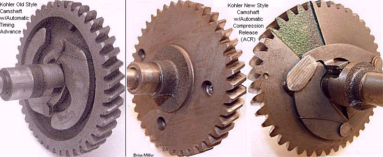 If you choose to reuse this camshaft to keep the engine "all original," when
reinstalling the cam in the engine block, make sure the punch marks on both
the cam gear and ignition cam (points lobe) are aligned. If this isn't done,
the ignition timing will be 180º off and the engine will not start.
Also, make sure the springs that's on the flyweights are properly positioned
on the ignition cam (points lobe) so there's pressure on each spring and
so the flyweights can move freely inward and outward when the engine is shut
down, and started up.
If you choose to reuse this camshaft to keep the engine "all original," when
reinstalling the cam in the engine block, make sure the punch marks on both
the cam gear and ignition cam (points lobe) are aligned. If this isn't done,
the ignition timing will be 180º off and the engine will not start.
Also, make sure the springs that's on the flyweights are properly positioned
on the ignition cam (points lobe) so there's pressure on each spring and
so the flyweights can move freely inward and outward when the engine is shut
down, and started up.
NEVER
INSTALL THE CAMSHAFT DRY! To prevent seizing of the cam on the pin when the
engine is ran for the first time, apply plenty of clean motor oil inside
the cam before installing it in the engine. This will provide vital lubrication
of the cam until crankcase oil reaches
it.
When setting the ignition timing
on the engine with this type of cam, set the points so they just begin to
open with the piston positioned on the compression stroke at 0º TDC
(T mark on the flywheel). When the engine starts, the points lobe automatically
rotates slightly, advancing the timing to 20º BTDC. Don't set the timing
at 20º BTDC (S mark on the flywheel) with this type of cam! Because
setting it at 20º BTDC will cause the engine to "kick back" when attempting
to start it. "Kick back" occurs when the flywheel/crankshaft suddenly and
violently rebounds or momentarily rotates in the opposite direction, which
is could bend or break the starter armature shaft or the aluminum starter
housing. And if it does start, the timing will automatically be advanced
to 40º BTDC, which will cause the engine to run too hot and prematurely
wear out. [Return To Previous Paragraph,
Section or Website]
Removing the Camshaft -
 Kohler's cast iron camshaft
is held in place by a 1/2" diameter steel pin that goes all the way through
the cam and engine block. The camshaft is removed by first removing the flywheel,
aluminum bearing plate, piston/rod assembly and crankshaft. Then use a long
steel rod that's slightly smaller than 1/2" in diameter and a medium size
hammer to drive out the pin from the PTO end of the block.
(See the photo to the right ->.) And when reinstalling the pin,
drive it in from the flywheel side until it's flush with the
block. The hole in the PTO end of the block is tapered to secure the pin
in place.
Kohler's cast iron camshaft
is held in place by a 1/2" diameter steel pin that goes all the way through
the cam and engine block. The camshaft is removed by first removing the flywheel,
aluminum bearing plate, piston/rod assembly and crankshaft. Then use a long
steel rod that's slightly smaller than 1/2" in diameter and a medium size
hammer to drive out the pin from the PTO end of the block.
(See the photo to the right ->.) And when reinstalling the pin,
drive it in from the flywheel side until it's flush with the
block. The hole in the PTO end of the block is tapered to secure the pin
in place.
NEVER
INSTALL A CAMSHAFT DRY! Always lubricate the pin and inside the camshaft
with plenty of motor oil or grease before reinstalling the cam in the block!
Failure to do so, just after starting the engine, friction from dry running
will cause the cam to seize on the pin. Severe damage to the pin, cam and
engine block will result!
To
prevent damaging or cracking the engine block, drive out the camshaft pin
from the PTO end towards the flywheel end. Do not drive out the pin from
the flywheel end! Doing this could also crack or break the camshaft!
The hole on the PTO end of the block for the cam pin is tapered. This is
what secures the pin in place.

 The 7" length camshaft pin
is no longer available from Kohler for their K241-K361 K-series engines.
It's replaced with a 6-3/4" length [Magnum] pin and a 1/2" diameter steel
expansion cup plug. When a 6-3/4" pin is installed in a K-series or Magnum
engine, it needs to be driven in 1/4" below the surface of the block (through
the flywheel end). Then the 1/2" cup plug needs to be installed to block
the hole, prevent an oil leak and keep the pin tight in the tapered hole
in the PTO end of the block. Failure to do this could cause the pin to loosen
in the tapered hole, and possibly spin with the cam, wearing the holes in
the block. And unlike the older K-series engines, being the Magnum bearing
plate/gasket doesn't cover the cam pin hole, a 1/2" steel expansion cup plug
(with a 6-3/4" pin) or
clear RTV silicone adhesive sealant (with a 7" pin) is
to be installed in front of the pin to prevent an oil leak. On the older
K-series engines, the bearing plate/gasket covers the pin, which seals in
the oil.
The 7" length camshaft pin
is no longer available from Kohler for their K241-K361 K-series engines.
It's replaced with a 6-3/4" length [Magnum] pin and a 1/2" diameter steel
expansion cup plug. When a 6-3/4" pin is installed in a K-series or Magnum
engine, it needs to be driven in 1/4" below the surface of the block (through
the flywheel end). Then the 1/2" cup plug needs to be installed to block
the hole, prevent an oil leak and keep the pin tight in the tapered hole
in the PTO end of the block. Failure to do this could cause the pin to loosen
in the tapered hole, and possibly spin with the cam, wearing the holes in
the block. And unlike the older K-series engines, being the Magnum bearing
plate/gasket doesn't cover the cam pin hole, a 1/2" steel expansion cup plug
(with a 6-3/4" pin) or
clear RTV silicone adhesive sealant (with a 7" pin) is
to be installed in front of the pin to prevent an oil leak. On the older
K-series engines, the bearing plate/gasket covers the pin, which seals in
the oil.
Advertisement: (Prices are subject to change without notice.)
| Click here to contact A-1 Miller's Performance Enterprises to place an order, send your parts for repairing, and/or for FREE professional and honest technical customer service assistance and support and payment options. Please contact A-1 Miller's if you need a part or parts, or service(s) performed that's not listed or mentioned in this website. | |||||
 Nylon
Governor Gears for general lawn and garden use. Also suitable for use in
a 4,000± RPM pulling engine. OEM Kohler part # A-235743-S. Nylon
Governor Gears for general lawn and garden use. Also suitable for use in
a 4,000± RPM pulling engine. OEM Kohler part # A-235743-S.
|
 Cast
Iron Governor Gear. Recommended for very high RPM or
open
RPM pulling engines. Will not explode like the nylon governor gears sometimes
do. (Kohler never made a steel governor gear.) Discontinued OEM Kohler part
# A-237031. Cast
Iron Governor Gear. Recommended for very high RPM or
open
RPM pulling engines. Will not explode like the nylon governor gears sometimes
do. (Kohler never made a steel governor gear.) Discontinued OEM Kohler part
# A-237031.
|
||||
  Governor Gear Stub Shafts. Fits Kohler engine models K141,
K160/K161, K181, L161,
L181 and M8. Dimensions: 3/8" diameter x .625" length. Each is press-fit
into block. Kohler part # 230125-S. Governor Gear Stub Shafts. Fits Kohler engine models K141,
K160/K161, K181, L161,
L181 and M8. Dimensions: 3/8" diameter x .625" length. Each is press-fit
into block. Kohler part # 230125-S.
Governor Gear Stub Shafts. Fits Kohler engine models K241, M10, K301, M12, K321, M14, K341, M16, K361 and all KT-series and Magnum opposed twin cylinder flathead engines. Dimensions: 3/8" diameter x .815" length. Each is press-fit into block. Kohler part # 235125-S.
|
|||||
 Thrust
Washers for Governor Gears. A thrust washer is required to prevent the
governor gear from wearing against the engine block when the governor is
under full pressure from the engine running at higher rpms. Many people are
not aware of this small, thin washer and it usually falls out and gets lost
while cleaning inside the block. Lubricate the governor stub shaft and thrust
washer with motor oil or automotive chassis lube before reinstalling to prevent
the governor gear from wearing until the crankcase oil reaches these areas.
Each measures 3/8" I.D. x 5/8" O.D.
Thrust
Washers for Governor Gears. A thrust washer is required to prevent the
governor gear from wearing against the engine block when the governor is
under full pressure from the engine running at higher rpms. Many people are
not aware of this small, thin washer and it usually falls out and gets lost
while cleaning inside the block. Lubricate the governor stub shaft and thrust
washer with motor oil or automotive chassis lube before reinstalling to prevent
the governor gear from wearing until the crankcase oil reaches these areas.
Each measures 3/8" I.D. x 5/8" O.D.
|
|||||
 Automatic
Compression Release (ACR) Spring. This tiny [hair-like] spring is hard
to find part nowadays. Fits Kohler engine models K141, K161, K181, M8, K241,
M10, K301, M12, K321, M14, K341, M16 and K361. Fits later one-piece camshafts
with the automatic compression release (opens exhaust valve slightly upon
the compression stroke) and not the early two-piece camshafts with the automatic
spark advance. FYI - If you have a Kohler 7-16hp ACR camshaft that was
broke in two by a thrown connecting rod, save the spring off of it. It can
be used on another good cam that may not have one. Or if your ACR spring
places little or weak pressure against the flyweights/levers, it can be re-bent
or reshape to its original condition to place sufficient tension against
the flyweights/levers. Automatic
Compression Release (ACR) Spring. This tiny [hair-like] spring is hard
to find part nowadays. Fits Kohler engine models K141, K161, K181, M8, K241,
M10, K301, M12, K321, M14, K341, M16 and K361. Fits later one-piece camshafts
with the automatic compression release (opens exhaust valve slightly upon
the compression stroke) and not the early two-piece camshafts with the automatic
spark advance. FYI - If you have a Kohler 7-16hp ACR camshaft that was
broke in two by a thrown connecting rod, save the spring off of it. It can
be used on another good cam that may not have one. Or if your ACR spring
places little or weak pressure against the flyweights/levers, it can be re-bent
or reshape to its original condition to place sufficient tension against
the flyweights/levers.
|
|||||
New-Style, One-Piece, OEM Kohler
Camshafts with Automatic Compression Release (ACR). NOTE:
May or may not come with the tiny (hair-like) automatic compression release
(ACR) spring (see above). If required, reuse the spring off of your camshaft.
IMPORTANT: Apply ample amount of clean motor
oil inside cam before installing to prevent seizing of cam on pin! This will
provide vital initial lubrication until crankcase oil reaches the cam/pin
when the engine is first ran. And when reusing lifters,
roughen lifter faces with 600 grit sandpaper to produce a new wear pattern
so the lifters will better grip the lobes and rotate slightly with every
lift to prevent wear to the lifters and lobes.
[Top of Page]
|
|||||
Professionally Reground 4,000± RPM Performance Torque Cast Camshaft for Kohler General-Use or Competition Pulling EnginesFYI - In order to gain the full benefit of a performance camshaft, just installing this type of cam will not greatly increase the power output of a Kohler engine. Along with the performance cam, the carburetor will need to be bored-out and reworked, the cylinder head will need to be milled .050" to raise the compression ratio, the valves/seats will need to be reworked, and installing an open/unrestricted exhaust header pipe will help, too. All of these things must work together so more air will enter the combustion chamber (and exit the chamber), which will build up more compression to allow the engine to produce more horsepower and torque.
FYI: When the cam lobes are reground, metal is removed from the base circle which reduce the diameter of the base circle in order retain maximum lift at the point on the lobe. The ramps on the lobes are also "rounded" to give the cam more duration. The cam grinding machine's grinding stones are about 1" wide, and after the cam grinding process, I have to manually grind metal away from the sides of the base circles so the edge of the lifters won't "ride up" on the ungrounded areas and hold the valves slightly open when they're supposed to be fully closed. I have to do this to every reground cam I have in stock. Some cam grinders apply a phosphate conversion coating (which resembles flat or matte black paint) to the entire camshaft, especially the lobes. This coating is to prevent galling (wear) during the break-in period and it also covers the secondary grinding areas on each side of the base circles of the lobes so they can't be readily easily seen or noticed. Motor oil with high zinc phosphate content will also protect the cam lobes and other internal moving engine parts from wear during break-in. Otherwise, if everything else is set up correctly with your engine, this cam should work fine. There's no need to be concerned when you receive the cam and see the metal ground away. Also, some of the cams I have, the points lobe is slightly worn. (It's hard to find a good used, 100% unworn cam nowadays.) I include a stainless steel points pushrod with a flared-end to make contact with the unworn areas of the lobe. The pushrod will need to be installed from inside the block before the cam is installed. IMPORTANT: To prevent seizing of camshaft on pin when engine is ran for the first time, apply plenty of motor oil on cam pin and inside cam before installing cam in engine. This will better protect the parts until crankcase oil reaches them. |
|||||
High Performance Cast Camshaft for Hot-Stock and Stock-Altered Kohler Competition Pulling Engines
|
|||||
 Medium Performance
(Blue) Single Valve Spring Set for Kohler engine
models K241, M10, K301, M12, K321, M14, K341, M16 and K361. Can also be used
in Kohler opposed twin cylinder engine models KT17 Series II, KT19 Series
II, M18, M20, K482, K532 and K582 for increased performance or competition
pulling and with the OEM Kohler stamped steel valve retainers listed below.
These springs are more aggressive than OEM Kohler valve springs, but less
aggressive than the red valve springs listed below. Suitable for competition
pulling engines only; not recommended for general yard or garden use. Best
to use the extreme duty
valve
spring compressor tool. Designed for the OEM Kohler stock cam or
our reground 4,000± RPM torque cam with stock lift in pulling engines
running up to 5,000 RPM for quicker valve closing to prevent valve float.
(Newton's third law of motion.) Valve float allows the engine
to momentarily lose compression, cause fuel to spray out the carburetor and
the engine will make a "hunt, hunt" sound at high RPM. As a result, the engine
will lose power, and as the weight box on the sled moves forward upon on
the tractor, the engine may not be able to recover. These springs can be
used with stock size valves, OEM Kohler stamped steel/non-rotator retainers
and keepers/locks/collets. Do not use with OEM
Kohler valve rotators with these springs! Rotators are thicker, and being
these performance springs are much longer (and slightly stiffer) than stock
springs (that require rotators), coil bind may result at full valve lift,
which could break the cam. Sold as a matched set. One spring is no stiffer
than the other. Same diameter as OEM Kohler springs. YouTube link:
Valve spring 8500 rpm. Dimensions: .697" I.D.; .953" O.D.;
2" uncompressed height. specifications: Seat load: 27 lbs. @ 1.650"; Open
load: 70 lbs. @ 1.200"; Coil bind: .920"; Spring rate (lbs/inch): 96. Made
by Comp Cams. Medium Performance
(Blue) Single Valve Spring Set for Kohler engine
models K241, M10, K301, M12, K321, M14, K341, M16 and K361. Can also be used
in Kohler opposed twin cylinder engine models KT17 Series II, KT19 Series
II, M18, M20, K482, K532 and K582 for increased performance or competition
pulling and with the OEM Kohler stamped steel valve retainers listed below.
These springs are more aggressive than OEM Kohler valve springs, but less
aggressive than the red valve springs listed below. Suitable for competition
pulling engines only; not recommended for general yard or garden use. Best
to use the extreme duty
valve
spring compressor tool. Designed for the OEM Kohler stock cam or
our reground 4,000± RPM torque cam with stock lift in pulling engines
running up to 5,000 RPM for quicker valve closing to prevent valve float.
(Newton's third law of motion.) Valve float allows the engine
to momentarily lose compression, cause fuel to spray out the carburetor and
the engine will make a "hunt, hunt" sound at high RPM. As a result, the engine
will lose power, and as the weight box on the sled moves forward upon on
the tractor, the engine may not be able to recover. These springs can be
used with stock size valves, OEM Kohler stamped steel/non-rotator retainers
and keepers/locks/collets. Do not use with OEM
Kohler valve rotators with these springs! Rotators are thicker, and being
these performance springs are much longer (and slightly stiffer) than stock
springs (that require rotators), coil bind may result at full valve lift,
which could break the cam. Sold as a matched set. One spring is no stiffer
than the other. Same diameter as OEM Kohler springs. YouTube link:
Valve spring 8500 rpm. Dimensions: .697" I.D.; .953" O.D.;
2" uncompressed height. specifications: Seat load: 27 lbs. @ 1.650"; Open
load: 70 lbs. @ 1.200"; Coil bind: .920"; Spring rate (lbs/inch): 96. Made
by Comp Cams.
|
 High Performance
(Red) Single Valve Spring Set for Kohler engine
models K241, M10, K301, M12, K321, M14, K341, M16 and K361. These are more
aggressive than the blue valve springs listed above
È. Suitable for competition pulling
engines that run at very high RPM or open RPM. Best to use the extreme duty
valve
spring compressor tool. Designed for cast or steel cams with up to
.400" lift in Hot-Stock or Stock-Altered competition pulling engines that
run at open RPM for quicker valve closing to prevent valve float.
(Newton's third law of motion.) Valve float allows the engine
to momentarily lose compression, cause fuel to spray out the carburetor and
the engine will make a "hunt, hunt" sound at high RPM. As a result, the engine
will lose power, and as the weight box on the sled moves forward upon on
the tractor, the engine may not be able to recover. These springs can be
used with stock size or oversize valves, OEM Kohler stamped steel/non-rotator
retainers and keepers/locks/collets. Do not use
with OEM Kohler valve rotators with these springs! Rotators are thicker,
and being these performance springs are much longer (and much stiffer) than
stock springs that require rotators, coil bind may result at full valve lift,
which could break the cam. Sold as a matched set. One spring is no stiffer
than the other. Same diameter as OEM Kohler springs. YouTube link:
Valve spring 8500 rpm. Dimensions: .697" I.D.; .953" O.D.;
2" uncompressed height. specifications: Seat load: 55 @ 1.500"; Open load:
127 @ 1.000"; Coil bind: .950"; Spring rate (lbs/inch): 144. Made by Comp
Cams. High Performance
(Red) Single Valve Spring Set for Kohler engine
models K241, M10, K301, M12, K321, M14, K341, M16 and K361. These are more
aggressive than the blue valve springs listed above
È. Suitable for competition pulling
engines that run at very high RPM or open RPM. Best to use the extreme duty
valve
spring compressor tool. Designed for cast or steel cams with up to
.400" lift in Hot-Stock or Stock-Altered competition pulling engines that
run at open RPM for quicker valve closing to prevent valve float.
(Newton's third law of motion.) Valve float allows the engine
to momentarily lose compression, cause fuel to spray out the carburetor and
the engine will make a "hunt, hunt" sound at high RPM. As a result, the engine
will lose power, and as the weight box on the sled moves forward upon on
the tractor, the engine may not be able to recover. These springs can be
used with stock size or oversize valves, OEM Kohler stamped steel/non-rotator
retainers and keepers/locks/collets. Do not use
with OEM Kohler valve rotators with these springs! Rotators are thicker,
and being these performance springs are much longer (and much stiffer) than
stock springs that require rotators, coil bind may result at full valve lift,
which could break the cam. Sold as a matched set. One spring is no stiffer
than the other. Same diameter as OEM Kohler springs. YouTube link:
Valve spring 8500 rpm. Dimensions: .697" I.D.; .953" O.D.;
2" uncompressed height. specifications: Seat load: 55 @ 1.500"; Open load:
127 @ 1.000"; Coil bind: .950"; Spring rate (lbs/inch): 144. Made by Comp
Cams.
|
||||
 OEM Kohler Stamped
Steel Valve Spring Isolator. Prevents engine operating heat from collapsing
or weakening valve springs. For general yard and garden engines. Not required
for competition pulling engines. Fits Kohler K-series and Magnum engine models
K141, K160/K161, K181, L161,
L181, M8, K241, M10, K301, M12, K321, M14, K341, M16, K361, KT17 (first
design), KT17 Series II, KT19 (first design), KT19 Series II, KT21, MV16,
M18, MV18, M20, MV20, K482, K532 and K582. For 5/8" O.D. valve guides. OEM
Kohler part # 235011-S. OEM Kohler Stamped
Steel Valve Spring Isolator. Prevents engine operating heat from collapsing
or weakening valve springs. For general yard and garden engines. Not required
for competition pulling engines. Fits Kohler K-series and Magnum engine models
K141, K160/K161, K181, L161,
L181, M8, K241, M10, K301, M12, K321, M14, K341, M16, K361, KT17 (first
design), KT17 Series II, KT19 (first design), KT19 Series II, KT21, MV16,
M18, MV18, M20, MV20, K482, K532 and K582. For 5/8" O.D. valve guides. OEM
Kohler part # 235011-S.
|
|||||
| FYI: The
OEM valve springs in various models of Kohler cast iron block engines are
not the same. They are not like the OEM springs that's used in a stock small
block Chevy V8's, which are the same. For some reason, Kohler installed a
specific valve spring in a certain model engine to match the cam profile
(lobe lift and duration) so the engine will perform best. And used valve
springs rarely lose adequate pressure. They can be reused as long as they're
not rusted or have been overheated. The rust-pitted areas is a weak spot
and when in operation and under pressure, the spring could
break.
|
|||||
OEM Kohler Stamped
Steel Valve Retainers. Used mainly for intake valve. Not recommended for
exhaust valve in general yard and garden equipment engines due to its inability
to rotate valve, which would allow carbon deposits to become lodged between
face and seat, causing a warped or burnt valve, resulting in loss of compression.
Fits Kohler K-series and Magnum K141, K160/K161, K181,
L161, L181, M8, K241,
M10, K301, M12, K321, M14, K341, M16, K361, KT17 (first design), KT17 Series
II, KT19 (first design), KT19 Series II, KT21, MV16, M18, MV18, M20, MV20,
K482, K532 and K582. Use only with longer (1-3/4" uncompressed length) OEM
Kohler or high-performance valve springs listed above
È. If used with the shorter (1-9/16"
uncompressed length) OEM Kohler valve spring, may cause lifter chatter at
higher RPM, valve float and/or engine misfire, and could possibly wear the
locking tang inside the keepers. For 5/16" diameter valve stems. Accepts
7º keepers/locks/collets listed below
Ê. .998" outside diameter. Made of
lightweight, heat-treated, hardened stamped steel. OEM Kohler part # 230011-S.
OEM Kohler Valve Rotators. Used
mainly for exhaust valve in general yard and garden equipment engines. Rotates
valve slightly as it opens to scrape away any carbon deposits from the face
and seat to prevent a warped or burnt valve, which would result in loss of
compression. Not needed for intake valve. Fits Kohler K-series and Magnum
K141, K160/K161, K181, L161,
L181, M8, K241, M10, K301, M12, K321, M14, K341, M16, K361, KT17 (first
design), KT17 Series II, KT19 (first design), KT19 Series II, KT21, MV16,
M18, MV18, M20, MV20, K482, K532 and K582. Also fits 6hp-18hp single and
opposed twin cylinder Briggs & Stratton engines. Use only with shorter
(1-9/16" uncompressed length) valve spring listed above
È. If used with longer 1-3/4" OEM Kohler
or high performance valve spring, coil bind may occur, resulting in possible
cam breakage. For 5/16" diameter valve stems. Accepts 7º
keepers/locks/collets listed below
Ê. OEM Kohler part # 52 413 01-S. Replaces
Briggs & Stratton part # 691939.
 High Performance Valve Spring
Retainers. Fits Kohler engine models K141, K160/K161, K181,
L161, L181, M8, K241,
M10, K301, M12, K321, M14, K341, M16, K361, KT17 (first design), KT17 Series
II, KT19 (first design), KT19 Series II, KT21, MV16, M18, MV18, M20, MV20,
K482, K532 and K582. To be used with our
BLUE medium performance valve springs
or our RED high performance valve springs,
or when used with OEM Kohler valve springs, the [longer] 1-11/16" or 1-3/4"
uncompressed height spring must be used. NOTE: The OEM Kohler stamped
steel retainers will work just as well with the blue or red springs.
Made of lightweight, hardened 4140 chrome-moly thick steel. Not made of stamped
steel. Accepts 7º keepers/locks/collets listed
below Ê. Replaces OEM Kohler part # 230011-S. High Performance Valve Spring
Retainers. Fits Kohler engine models K141, K160/K161, K181,
L161, L181, M8, K241,
M10, K301, M12, K321, M14, K341, M16, K361, KT17 (first design), KT17 Series
II, KT19 (first design), KT19 Series II, KT21, MV16, M18, MV18, M20, MV20,
K482, K532 and K582. To be used with our
BLUE medium performance valve springs
or our RED high performance valve springs,
or when used with OEM Kohler valve springs, the [longer] 1-11/16" or 1-3/4"
uncompressed height spring must be used. NOTE: The OEM Kohler stamped
steel retainers will work just as well with the blue or red springs.
Made of lightweight, hardened 4140 chrome-moly thick steel. Not made of stamped
steel. Accepts 7º keepers/locks/collets listed
below Ê. Replaces OEM Kohler part # 230011-S.
|
|||||
 5/16" Valve Keepers/Locks/Collets for all Kohler K-series
and Magnum K141-K361 cast iron engines, and KT series and Magnum opposed
twin cylinder flathead engines, including K482, K532 and K582. Also fits
6hp-18hp single- and opposed twin-cylinder Briggs & Stratton exhaust
valves. Can be used with 8mm valve stems and high performance valve springs
listed above È. NOTE: Valve keepers
usually don't wear or get damaged because they don't rotate on the valve
stem. To check yours, with a valve out of the engine, install a valve retainer
or rotator on the valve, then the keepers, and then pull back hard on the
retainer or rotator. If the retainer or rotator holds or squeezes the keepers
tight in the groove, then they can be reused. Replaces Briggs & Stratton
part # 494553.
5/16" Valve Keepers/Locks/Collets for all Kohler K-series
and Magnum K141-K361 cast iron engines, and KT series and Magnum opposed
twin cylinder flathead engines, including K482, K532 and K582. Also fits
6hp-18hp single- and opposed twin-cylinder Briggs & Stratton exhaust
valves. Can be used with 8mm valve stems and high performance valve springs
listed above È. NOTE: Valve keepers
usually don't wear or get damaged because they don't rotate on the valve
stem. To check yours, with a valve out of the engine, install a valve retainer
or rotator on the valve, then the keepers, and then pull back hard on the
retainer or rotator. If the retainer or rotator holds or squeezes the keepers
tight in the groove, then they can be reused. Replaces Briggs & Stratton
part # 494553.
|
|||||
Heavy Duty Scissors-Type Valve Spring Compressor Tool. Use to remove and reinstall OEM and heavy single valve springs in all flathead (valves in block) small engines. New. $40.00 each, plus shipping & handling. |
Heavy Duty C-Shaped Valve Spring Compressor Tool. Use to remove and reinstall OEM and heavy aftermarket single valve springs in all flathead (valves in block) and OHV small engines. New. $40.00 each, plus shipping & handling. |
Extreme Duty Clamp-Type Valve Spring Compressor Tool. Made of heat-treated steel. Highly recommended to remove and reinstall high pressure aftermarket single- and double-valve springs in virtually all flathead (valves in block) competition pulling engines. New. $25.00 each, plus shipping & handling. |
|||
 Valve Lifters/Tappets.
Replace worn lifter(s) to prevent erratic valve action and/or premature cam
lobe wear. Non-adjustable; grind end of valve stems with piston positioned
at TDC on compression stroke to set valve clearances. Valve Lifters/Tappets.
Replace worn lifter(s) to prevent erratic valve action and/or premature cam
lobe wear. Non-adjustable; grind end of valve stems with piston positioned
at TDC on compression stroke to set valve clearances.
Wide Base Adjustable Valve Lifters/Tappets. Fits Kohler engine models K241, M10, K301, M12, K321, M14, K341 and M16. Dimensions: 1.280" base diameter x .6225" stem diameter x 2.750"-3.000" overall (adjustable) length. For competition pulling engines with a high-performance cam with .400"-.575" lift. Set valve clearances with piston positioned at TDC on compression stroke. May need to reuse 7/16" adjusters from OEM Kohler lifters with these wide base lifters. (These are NOT Jeep lifters! Jeep lifters are too long and will not fit Kohler engines.)
|
|||||
 Camshaft
Pin. Fits Kohler K-series and Magnum engine models K241, M10, K301, M12,
K321, M14, K341, M16 and K361. Made of 1144 Stress Proof Steel Pin. 1/2"
diameter x 7" length. A-1 Miller's part. Replaces discontinued Kohler part
# 235053-S (K-series; 7" length) and discontinued 47 380 09-S (Magnum; 6-3/4"
length). $12.00 each, plus shipping & handling. Camshaft
Pin. Fits Kohler K-series and Magnum engine models K241, M10, K301, M12,
K321, M14, K341, M16 and K361. Made of 1144 Stress Proof Steel Pin. 1/2"
diameter x 7" length. A-1 Miller's part. Replaces discontinued Kohler part
# 235053-S (K-series; 7" length) and discontinued 47 380 09-S (Magnum; 6-3/4"
length). $12.00 each, plus shipping & handling. |
|||||
|
|||||
And if you're wondering, all of Kohler's stock camshafts are removed by driving out the steel pin that it rides on from the PTO end of the block (opposite flywheel end) with a hammer and long steel pin that's slightly smaller than 1/2" in diameter. Also, there should be one or two shims on the pin. Be sure not to loose them. You'll need them when you reinstall the cam.
NOTE: Use stock OEM valve springs with a stock OEM or K361 cam if an engine is going to turn 4,000 RPM or below. And use Stock-Altered (single) valve springs for above 4,000 RPM. Because cast iron is brittle, do not use double (Super-Stock) valve springs with the K361 or any [welded up] OEM camshaft! Also, with double springs, the compression release lever on the cam could break off. And be gentle when handling a cast iron camshaft! If the cam is mishandled, the lightweight spring that controls the compression release mechanism could come off the levers when installed in the engine. If this happens, the engine would crank over under full compression, making it very hard or impossible to start.
When
having a camshaft reground, trust only places that use a specialized precision
cam grinding machine. Because if the lobes are "hand ground" or if ground
any other method, the cam may not work as well.
The cast iron camshaft that originally came in the Kohler model K361 engine is no longer available from Kohler. If you're lucky, you might find a new cam from old stock. The part number for this cam is 45 010 05S. They fit the K241-K341 flathead engines, too. Good for up to 4,000 RPM.) They work great in a stock engine!
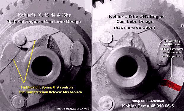 NOTE:
The K361 cam works great for more power in a K241 and K301 engines, but it
won't do quite as much as the cubic inches increases. Although it will work
great in the K321 and K341 engines, but it creates less noticeable power
increase in the K321 and especially the K341 engine. However, it does help
in the power increase in a K341, it's just less noticeable because of the
bigger cubic inch displacement. A "mild-performance" cam, such as the K361
cam, works better in engines with smaller cubic inches. A somewhat bigger
cam is required as the cubic inches are increased. Because bigger engines
needs to draw in and expel more air (at 4,000 RPM with stock valves), and
the K361 cam has it's limits when used in the bigger engines. And because
of it's short lift and duration, it makes it's most power up to around 4,000
RPM.
NOTE:
The K361 cam works great for more power in a K241 and K301 engines, but it
won't do quite as much as the cubic inches increases. Although it will work
great in the K321 and K341 engines, but it creates less noticeable power
increase in the K321 and especially the K341 engine. However, it does help
in the power increase in a K341, it's just less noticeable because of the
bigger cubic inch displacement. A "mild-performance" cam, such as the K361
cam, works better in engines with smaller cubic inches. A somewhat bigger
cam is required as the cubic inches are increased. Because bigger engines
needs to draw in and expel more air (at 4,000 RPM with stock valves), and
the K361 cam has it's limits when used in the bigger engines. And because
of it's short lift and duration, it makes it's most power up to around 4,000
RPM.
FYI - If you have a Kohler 7-16hp ACR camshaft that was broke in two by a thrown connecting rod, save the spring off of it. It can be used on another good cam that may not have one. Or if your ACR spring places little or weak pressure against the flyweights/levers, it can be re-bent or reshape to its original condition to place sufficient tension against the flyweights/levers.
Setting the Valve Timing For Cast Iron Kohler Cams Without a Machined Adjustable Gear -
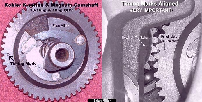 If you're planning to use a
factory stock cast iron cam (such as a reground Kohler cam or the K361 Kohler
cam), or if the cam grinder person ground your high-performance cast cam
"right on the specifications," it shouldn't need to be degreed in. Just install
it in the engine, usually along with a thin and thick shim (.005" and .010",
respectively) toward the flywheel end, and it should be set pretty close
to specs, if not right on it. But steel cams with an adjustable gear will
probably need to be degreed in according to the provided specs sheet. Install
shim(s) with a steel cam only to prevent wear on both the camshaft and engine
block. To accurately set the valve timing on a Kohler or virtually any 4-cycle
engine, simply align the punch [timing] mark on the camshaft gear, which
is located between two gear teeth, with the groove or [timing] mark on or
next to the crankshaft gear, which is located at one gear tooth.
If you're planning to use a
factory stock cast iron cam (such as a reground Kohler cam or the K361 Kohler
cam), or if the cam grinder person ground your high-performance cast cam
"right on the specifications," it shouldn't need to be degreed in. Just install
it in the engine, usually along with a thin and thick shim (.005" and .010",
respectively) toward the flywheel end, and it should be set pretty close
to specs, if not right on it. But steel cams with an adjustable gear will
probably need to be degreed in according to the provided specs sheet. Install
shim(s) with a steel cam only to prevent wear on both the camshaft and engine
block. To accurately set the valve timing on a Kohler or virtually any 4-cycle
engine, simply align the punch [timing] mark on the camshaft gear, which
is located between two gear teeth, with the groove or [timing] mark on or
next to the crankshaft gear, which is located at one gear tooth.
If there's no timing marks on the crank or cam gears or if there's multiple marks on either gear (these can be confusing), or if the crankshaft gear is pressed-on, (most crankshafts have a pin or key that keeps the gear from moving), to set the correct crank to cam timing on virtually any engine, automotive or small, with the crankshaft installed in the block, position the piston at true Top Dead Center (TDC). (True TDC is when the piston is at the very top of the cylinder.) If it's a multi-cylinder engine, use the #1 cylinder only for the piston and valves described in this paragraph. Install the camshaft and valves (or lifters if the engine is OHV), and then check for correct crank to cam gear teeth alignment by rotating the crankshaft so the piston is at true TDC on the exhaust stroke. Now slightly rotate the crankshaft back and forth by hand. When one valve opens (or lifter raises) slightly and the other valve closes (or lifter lowers) slightly, and vice-versa, and when the piston is either slightly before or after TDC while rocking the crankshaft, this is when the valve timing is set correctly. On the exhaust stroke, neither valve (or lifter) should be fully closed (or lifter resting on the base circle of the cam lobe) when the piston is at the TDC position. (This is called valve overlap.) With a pressed-on gear having no pin or key to secure it in place, after the timing is correctly set, place a small bead of weld on the gear and crankshaft or braze the gear to the crankshaft to prevent it from moving again.
On a multiple cylinder engine, align the cam and crank gears with the piston in the #1 cylinder positioned at TDC on the compression stroke. On a V-twin or opposed twin cylinder engine, the #1 cylinder is the one closest to the flywheel. On an automotive engine, the #1 cylinder is the one closest to the front of the engine, or harmonic balancer. Align the cam gear tooth with the crank gear, and to check for correct cam to crankshaft alignment, rotate the crankshaft 180º so the #1 piston is at true TDC on the exhaust stroke. Then slightly rock the crankshaft back and forth by hand. One valve on the #1 cylinder should slightly open and the other valve on the same cylinder should slightly close. The piston should be either slightly after or before TDC while rocking the crankshaft, this is when the valve timing is set correctly.
Why Engines Need the Automatic Compression Release (ACR) Mechanism -
The reason automatic compression release (ACR) is installed on small engines nowadays is because the engine has fixed (non-adjustable) advanced ignition timing. If it didn't have an ACR, under full compression, with fixed advanced timing, and at cranking speed, the engine would "kick back" when attempting to start it. "Kick back" occurs when the flywheel/crankshaft suddenly and violently rebounds or momentarily rotates in the opposite direction, which is could bend or break the starter armature shaft or the aluminum starter housing. By relieving about half the compression pressure in the combustion chamber, this allows the engine to crank over easier and start much quicker. A smaller starter motor and battery can be used.
FYI - If you have a Kohler 7-16hp ACR camshaft that was broke in two by a thrown connecting rod, save the spring off of it. It can be used on another good cam that may not have one. Or if your ACR spring places little or weak pressure against the flyweights/levers, it can be re-bent or reshape to its original condition to place sufficient tension against the flyweights/levers.
When advancing the ignition timing past
24º± BTDC, and if the camshaft has a working automatic compression
release mechanism, the compression release will need to be disabled (tied
down) with a nylon zip tie or baling wire, or removed entirely. The reason
being, with the excessive advanced timing, the compression release will open
the exhaust valve when spark occurs, and the engine will pop out the exhaust,
not be able to start, or be hard to start. Without a compression release,
to make the engine easier to crank over and start under full compression,
a high torque starter motor with separate starter and ignition switches will
need to be used to prevent engine "kick back." If the engine
"kicks back" too many times when attempting to start it, this could bend
or break the starter motor armature shaft, or break the aluminum
casing!
On certain older Kohler K-series engines and virtually older automotive engines with the ignition distributor, at cranking speed, the ignition timing is positioned at or close to 0º TDC, and with a mechanically-controlled flyweight timing advance built into the distributor, the engine starts easily under full compression, and when the engine starts, centrifugal force automatically advances the timing to where it needs to be so the engine will produce full power. These engines require a high-torque starter motor and bigger battery.
An Easy Way to Start an Engine under Full Compression and with Advanced Ignition Timing with No Automatic Compression Release to Prevent "Kick Back":
With the timing permanently set in the advanced position, two separate electric switches will need to be used - one being a push button to crank the engine (with a gear starter), and the other being an ordinary OFF/ON toggle switch to power the ignition. To make this work, first crank the engine to get it spinning over (if the starter motor is strong enough), choke it, and then flip the ignition (toggle) switch to "put the spark to it." Doing this will allow the engine to start easily every time. Because the energy stored in the spinning weight of the heavy flywheel makes it impossible for the engine to momentarily "kick back" under full compression with no [advanced] spark. This starting method is also recommended for pulling engines (with points or crank trigger ignition) having a high-performance camshaft and no compression release.
How the Mechanical Automatic Compression Release (ACR) Operates -
 The ACR mechanism consist
of two flyweights and a small [hair-like] spring attached to the gear on
the camshaft. When the engine is rotating at low cranking speeds (600 RPM
or lower), the flyweights are held inward by the small spring in the position
shown in the 1st drawing to the right ->, resulting in an effective
compression ratio loss of about 2:1 during cranking.
The ACR mechanism consist
of two flyweights and a small [hair-like] spring attached to the gear on
the camshaft. When the engine is rotating at low cranking speeds (600 RPM
or lower), the flyweights are held inward by the small spring in the position
shown in the 1st drawing to the right ->, resulting in an effective
compression ratio loss of about 2:1 during cranking.
After the engine speed increases above 600 RPM (engine starts and runs), centrifugal force automatically moves the flyweights outward (in the position shown in the 2nd drawing to the right ->). In this position, the tab on the larger flyweight drops into a recess in the exhaust cam lobe. When in the recess, the tab has no effect on the exhaust valve and the engine operates at full compression to produce full power. Kohler revealed their Automatic Compression Release (ACR) in 1965.
If an engine fails to crank over past the compression stroke, and the battery is fully charged and in good condition, and the starter motor is also in good condition, then chances are, the ACR spring on the camshaft is placing insufficient pressure on the flyweights to retain or hold them inward. To fix this, remove the spring and carefully bend it inward by hand until it forms a closer V-shape to about a 60º angle, and then reinstall the spring on the cam. Then hand test the flyweights to make sure they return and stay inward. Sometimes I have to do this on some of the engines that I rebuild so my customers will not have any problems when starting the engine. It's another small detail to pay attention to when rebuilding an older Kohler engine.
FYI - If you have a Kohler 7-16hp ACR camshaft that was broke in two by a thrown connecting rod, save the spring off of it. It can be used on another good cam that may not have one. Or if your ACR spring places little or weak pressure against the flyweights/levers, it can be re-bent or reshaped to its original condition to place sufficient tension against the flyweights/levers.
Performing a Compression Test on an Air-Cooled Gas Engine -
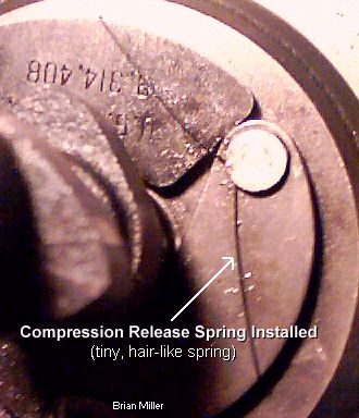 The compression relief is a
mechanical swing arm on the cam. At cranking speeds, it holds the exhaust
valve open about .050" to relief about half the compression so the engine
will start easier. Because no engine can start under full compression with
advanced ignition timing. When the engine starts, the increased RPM or
centrifugal weight opens the swing arm so the exhaust valve will have 100%
contact with the seat, allowing the engine to run under full compression.
The compression relief is a
mechanical swing arm on the cam. At cranking speeds, it holds the exhaust
valve open about .050" to relief about half the compression so the engine
will start easier. Because no engine can start under full compression with
advanced ignition timing. When the engine starts, the increased RPM or
centrifugal weight opens the swing arm so the exhaust valve will have 100%
contact with the seat, allowing the engine to run under full compression.
The compression relief mechanism on the camshaft relieves about half of the compression pressure in the combustion chamber at cranking speeds. When the engine starts, the compression builds up to 100%. On OEM camshafts with a working compression relief mechanism and if the valves are adjusted to specs, the compression relief relieves about half the compression from the combustion chamber at cranking speeds. So when performing a compression test (with a gauge) on an air-cooled engine, keep in mind that, depending on how the engine is built, the compression ratio or the compression pressure can vary a lot from one engine to another. It depends on the size of the bore and stroke, if the head is milled flat or milled out for high lift valve clearance, if the camshaft has a compression relief or not, how much duration the cam has and the valve head diameters. When performing a compression test on a K241 Kohler engine, it can range anywhere from 98 to 150 psi. On a K301, it can be from 112 to 170 psi. On a K321, it can range from 120 to 190 psi. And on a K341, it can be from 127 up to 192 psi. But as an engine wears, the compression will become less.
And cranking speeds, a long duration cam will relieve some of the combustion chamber pressure, resulting in a lower than normal reading. The more the duration, the lower the reading. To obtain an accurate compression pressure reading, perform the test with a fully charged battery and the throttle in the wide open position. Now perform the test. Then calculate the reading with the duration of the cam in the engine against the duration of a stock OEM cam. Example: If the compression pressure is 100 psi, I multiple 100 by 285 (duration of cam that's in the engine) and then I divide the answer by 223º (duration of a stock OEM cam), which gives A-1 Miller's 128 psi. And if a cam has a compression relief mechanism, the compression reading will be cut in half.
Available Soon - Detailed Illustrated Plans on How to Construct a Professional Pull-Back and Self-Propelled Garden Tractor/Small Wheel Mini Rod Pulling Sleds (Weight Transfer Machines) - [Top of Page]
 FYI - I'm getting closer to
completing my sled plans. But being I have lots of work to do in my shop,
I work on designing my sled plans in my spare time. As soon as my plans with
an inventory list of parts to use and with illustrations are perfected, I'll
post the announcement in my websites. And as for prices of the pull-back
sled and self-propelled sled plans, I'm not sure yet. Make me an offer and
I'll consider it. And remember - Perfection takes time. If it's worth having,
it's worth waiting for. It'll be money well spent. Contact
information below.
FYI - I'm getting closer to
completing my sled plans. But being I have lots of work to do in my shop,
I work on designing my sled plans in my spare time. As soon as my plans with
an inventory list of parts to use and with illustrations are perfected, I'll
post the announcement in my websites. And as for prices of the pull-back
sled and self-propelled sled plans, I'm not sure yet. Make me an offer and
I'll consider it. And remember - Perfection takes time. If it's worth having,
it's worth waiting for. It'll be money well spent. Contact
information below.
Complete Narrowed Automotive Rear End/Differential for Use in Garden Tractor Pulling Sled - [Top of Page]
Details Include -
 When connected to an automotive
3- or 4-speed manual transmission, this narrowed rear end controls the movement
of the weight box in a garden tractor pulling sled (weight transfer machine).
When connected to an automotive
3- or 4-speed manual transmission, this narrowed rear end controls the movement
of the weight box in a garden tractor pulling sled (weight transfer machine).
 To place an order, send your item(s) for repairing, and/or
for customer service assistance, and FREE honest and accurate technical support,
please contact: A-1 Miller's Performance Enterprises, 12091 N Route B,
Hallsville, MO (Missouri) 65255-9604 USA. Please call in your order or send
an email with a list parts you need and your contact information.
To place an order, send your item(s) for repairing, and/or
for customer service assistance, and FREE honest and accurate technical support,
please contact: A-1 Miller's Performance Enterprises, 12091 N Route B,
Hallsville, MO (Missouri) 65255-9604 USA. Please call in your order or send
an email with a list parts you need and your contact information.
 Phone: 1-573-881-7229 (cell;
call, text or leave voicemail). Please call Monday-Friday, 9am to 5pm, Central
time zone, except holidays. If no answer, please try again later.
Phone: 1-573-881-7229 (cell;
call, text or leave voicemail). Please call Monday-Friday, 9am to 5pm, Central
time zone, except holidays. If no answer, please try again later.
 E-mail:
pullingtractor@aol.com. A-1 Miller's
shop is open to the public Monday-Friday, 9am to 5pm, Central time zone,
with an appointment on weekends, except holidays. If you're the kind of person
who don't trust delivery/shipping companies (mis)handling your high-dollar
and fragile merchandise, you can make the long drive to A-1 Miller's new
shop (click image to the right) to personally purchase parts, or drop off
and/or pick up your carburetor, clutch assembly, and/or other parts for repairing
and/or rebuilding. Or visit our new shop to drop off your parts. Please contact
us before coming so we'll be at our shop waiting for your arrival. When you
visit our shop, you will be dealing directly with the owner for the best
customer service. "The road to a [trusted] friend's house (or shop) is
never long." Don't sacrifice quality workmanship for distance.
Payment Options below.
Photos
of our new building/shop are posted here!
12091 N Route B, Hallsville, MO - Google Maps.
[Return To Previous Paragraph, Section
or Website]
E-mail:
pullingtractor@aol.com. A-1 Miller's
shop is open to the public Monday-Friday, 9am to 5pm, Central time zone,
with an appointment on weekends, except holidays. If you're the kind of person
who don't trust delivery/shipping companies (mis)handling your high-dollar
and fragile merchandise, you can make the long drive to A-1 Miller's new
shop (click image to the right) to personally purchase parts, or drop off
and/or pick up your carburetor, clutch assembly, and/or other parts for repairing
and/or rebuilding. Or visit our new shop to drop off your parts. Please contact
us before coming so we'll be at our shop waiting for your arrival. When you
visit our shop, you will be dealing directly with the owner for the best
customer service. "The road to a [trusted] friend's house (or shop) is
never long." Don't sacrifice quality workmanship for distance.
Payment Options below.
Photos
of our new building/shop are posted here!
12091 N Route B, Hallsville, MO - Google Maps.
[Return To Previous Paragraph, Section
or Website]
Payment Options, and We Ship to Canada and
Worldwide 
Item(s) in a package or cushioned envelope weighing less than 1 lb. is sent
by US Postal Service Airmail Letter Post for a 4-7 days delivery. Packaged
item(s) weighing over 1 lb. and up to 66 lb. is sent by US Postal Service
Airmail Parcel Post for a 4-10 days delivery. I cannot use the US Postal
Services' Flat Rate Priority Mail envelopes and boxes to ship outside U.S.
territories. Item(s) weighing over 67 lbs. or more is sent by FedEx Ground
or equivalent services. We try to keep our shipping cost to customers within
reason. Therefore, we don't ship our products in a fancy-looking package
with our company name and/or logo on it because most customers will just
toss it in the trash after they remove the contents. And being there is no
USPS tracking number outside the US, all I can do is make sure I write your
address correctly on the customs form and on your package.
My websites are not set up to process orders and accept payments. Therefore, to place an order with me, please call either number above or send an email with a list of parts you need, with your name, complete and correct postal mailing address and phone number. For payment options, I accept cash (in person), USPS Postal Money Orders, cashier's checks, business checks, MasterCard, VISA, Discover, American Express (please add 2.5% to the total amount for the credit/debit card processor's surcharge). If paying with a credit/debit card, please call me at either number above. Or to make a payment to me through PayPal, please click this link: https://www.paypal.com. Or use Cash App (username: pullingtractor) or Venmo (username: Pullingtractor) to make a payment to me. And be sure to mention a description of what the payment is for with your full name, postal address, phone number and email address. If sending a money order or cashier's check, please include a note in the envelope with your name, complete mailing address, phone number, email address and a description of what the payment is for. I'll make a note of your order when I have all your information, and I may have to order some of the parts on your list, which should take a few days to come in, but I will send everything to you as soon as I have the parts in stock after I receive your payment.


Return To Previous Website | Top of Page | Copyright © 1996-Present. This website created, designed and maintained by A-1 Miller's Performance Enterprises

 Exhaust Valves. Fits Kohler engine
models K141, K160/K161 K181,
Exhaust Valves. Fits Kohler engine
models K141, K160/K161 K181,
 Kohler Engine Model K361
Intake and Exhaust Valves -
Kohler Engine Model K361
Intake and Exhaust Valves -
 A-1 Miller's High Quality
Aftermarket Intake Valve. Fits Kohler engine models KT17 (first design),
KT17 Series II, MV16, M18 and MV18. 45º face angle, 8mm diameter stem;
requires 8mm
A-1 Miller's High Quality
Aftermarket Intake Valve. Fits Kohler engine models KT17 (first design),
KT17 Series II, MV16, M18 and MV18. 45º face angle, 8mm diameter stem;
requires 8mm  A-1 Miller's High Quality
Aftermarket Intake Valve. Fits Kohler engine models KT19 first design, KT19
Series II, and early M20 and MV20. 45º face angle. This valve can be
used for the intake or exhaust to match a 46º seat, if desired. Has
an 8mm diameter stem; requires 8mm
A-1 Miller's High Quality
Aftermarket Intake Valve. Fits Kohler engine models KT19 first design, KT19
Series II, and early M20 and MV20. 45º face angle. This valve can be
used for the intake or exhaust to match a 46º seat, if desired. Has
an 8mm diameter stem; requires 8mm 
 Oversize Valves
for High RPM Kohler Pulling Engines. Each can be used as intake valve for
Kohler 10-16hp pulling engines, or as exhaust valve (with a 20%± bigger
intake valve). Each have a 45º face angle for a 46º seat, but can
be reground to 30º to match a 31º seat. OEM Kohler valve
Oversize Valves
for High RPM Kohler Pulling Engines. Each can be used as intake valve for
Kohler 10-16hp pulling engines, or as exhaust valve (with a 20%± bigger
intake valve). Each have a 45º face angle for a 46º seat, but can
be reground to 30º to match a 31º seat. OEM Kohler valve
 Antique Engine Valve. Fabricate
a new replacement valve for your antique engine. NOTE: You will need to
send the original valve to A-1 Miller's so it can replicated from new
material(s).
Antique Engine Valve. Fabricate
a new replacement valve for your antique engine. NOTE: You will need to
send the original valve to A-1 Miller's so it can replicated from new
material(s).
 Stock (centered) Cast Iron
Valve Guides. Fits Kohler engine models K141, K160/K161,
Stock (centered) Cast Iron
Valve Guides. Fits Kohler engine models K141, K160/K161,
 Stock (centered) Cast Iron
Valve Guides. Fits Kohler engine models K241, M10, K301, M12, K321, M14,
K341, M16, K482, K532 and K582. Dimensions: .310" I.D. x .629" O.D. x 2.135"
overall length. NOTE: Use my
Stock (centered) Cast Iron
Valve Guides. Fits Kohler engine models K241, M10, K301, M12, K321, M14,
K341, M16, K482, K532 and K582. Dimensions: .310" I.D. x .629" O.D. x 2.135"
overall length. NOTE: Use my 
 Cast Iron Valve Guides.
Fits Kohler engine model K361 cylinder head.
Cast Iron Valve Guides.
Fits Kohler engine model K361 cylinder head.
 Stock (centered) Cast Iron
Valve Guides. Fits Kohler engine models MV16, KT17, KT17 Series II, KT19,
KT19 Series II, M18, MV18, M20 and MV20. NOTE: Use my
Stock (centered) Cast Iron
Valve Guides. Fits Kohler engine models MV16, KT17, KT17 Series II, KT19,
KT19 Series II, M18, MV18, M20 and MV20. NOTE: Use my
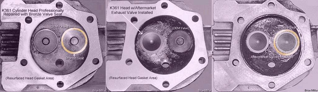
 Professionally replace loose and/or broken OEM valve seat with
a new high quality aftermarket hardened steel seat insert. $200.00 each
for labor and new seat, plus return shipping & handing.
Professionally replace loose and/or broken OEM valve seat with
a new high quality aftermarket hardened steel seat insert. $200.00 each
for labor and new seat, plus return shipping & handing.
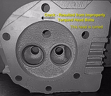
 Kohler Engine Model K361 (OHV 18hp) Cylinder Head Assembly.
Professionally rebuilt and fully assembled. No cracks. Cooling fins, spark
plug threads and bolt hole threads are all in good condition. Valve
seats and/or valve guides reground, repaired or replaced, where applicable.
Includes valves, springs, rotators, stabilizers and keepers. Cleaned and
resurfaced on a wide, flat
Kohler Engine Model K361 (OHV 18hp) Cylinder Head Assembly.
Professionally rebuilt and fully assembled. No cracks. Cooling fins, spark
plug threads and bolt hole threads are all in good condition. Valve
seats and/or valve guides reground, repaired or replaced, where applicable.
Includes valves, springs, rotators, stabilizers and keepers. Cleaned and
resurfaced on a wide, flat
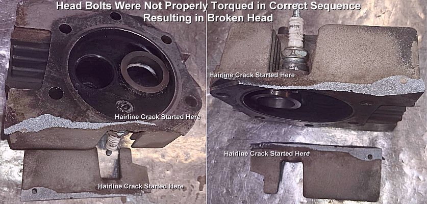

 Crankcase Breather Assembly and Cover Gaskets. FYI - The
gaskets listed below are interchangeable between the Kohler engine models
K141, K160/K161,
Crankcase Breather Assembly and Cover Gaskets. FYI - The
gaskets listed below are interchangeable between the Kohler engine models
K141, K160/K161,  Crankcase Breather Reed Plate
Inner Gaskets. Fits Kohler engine models K241, M10, K301, M12, K330/K331,
K321, M14, K341, M16 and K361.
Crankcase Breather Reed Plate
Inner Gaskets. Fits Kohler engine models K241, M10, K301, M12, K330/K331,
K321, M14, K341, M16 and K361.
 Crankcase Breather Cover Outer
Gaskets. Fits Kohler engine models K241, M10, K301, M12, K330/K331, K321,
M14, K341, M16 and K361.
Crankcase Breather Cover Outer
Gaskets. Fits Kohler engine models K241, M10, K301, M12, K330/K331, K321,
M14, K341, M16 and K361.
 Crankcase Breather Reed Valve.
Fits Kohler engine models K241, M10, K301, M12, K330/K331, K321, M14, K341,
M16 and K361. Replace damaged or rusted reed valve to prevent loss of oil
through breather vent hole, prevent outside dust and dirt from being drawn
into crankcase, and maintain crankcase vacuum so engine will produce more
power. OEM Kohler part # 235047-S.
Crankcase Breather Reed Valve.
Fits Kohler engine models K241, M10, K301, M12, K330/K331, K321, M14, K341,
M16 and K361. Replace damaged or rusted reed valve to prevent loss of oil
through breather vent hole, prevent outside dust and dirt from being drawn
into crankcase, and maintain crankcase vacuum so engine will produce more
power. OEM Kohler part # 235047-S.
 Old Style Replacement Neoprene
Rubber Umbrella Check Valve and Crankcase Breather Plate w/Umbrella Check
Valve used on Kohler KT-series and Magnum opposed twin cylinder engine models
KT17 (first design), KT17 Series II, KT19 (first design), KT19 Series II,
KT21, MV16, M18, MV18, M20 and MV20. Replace deteriorated rubber umbrella
check valve to prevent loss of oil through breather vent hole, prevent outside
dust and dirt from entering crankcase and maintain crankcase vacuum so engine
will produce more power. NOTE: The old style breather with the umbrella
valve works just as well as the new style breather with the steel reed valve.
So if the umbrella valve of your breather is damaged, it can be replaced.
NOTE: It cost less to just replace the umbrella valve than the entire breather
plate with the steel reed valve.
Old Style Replacement Neoprene
Rubber Umbrella Check Valve and Crankcase Breather Plate w/Umbrella Check
Valve used on Kohler KT-series and Magnum opposed twin cylinder engine models
KT17 (first design), KT17 Series II, KT19 (first design), KT19 Series II,
KT21, MV16, M18, MV18, M20 and MV20. Replace deteriorated rubber umbrella
check valve to prevent loss of oil through breather vent hole, prevent outside
dust and dirt from entering crankcase and maintain crankcase vacuum so engine
will produce more power. NOTE: The old style breather with the umbrella
valve works just as well as the new style breather with the steel reed valve.
So if the umbrella valve of your breather is damaged, it can be replaced.
NOTE: It cost less to just replace the umbrella valve than the entire breather
plate with the steel reed valve.
 New Style Crankcase Breather
Plate with Steel Reed Valve. Fits Kohler KT-series and Magnum opposed twin
cylinder engine models KT17 (first design), KT17 Series II, KT19 (first design),
KT19 Series II, KT21, MV16, M18, MV18, M20 and MV20. Each listed below replaces
OEM Kohler part # 52 254 07. NOTE: The two items listed below are basically
the same part with different part numbers and prices.
New Style Crankcase Breather
Plate with Steel Reed Valve. Fits Kohler KT-series and Magnum opposed twin
cylinder engine models KT17 (first design), KT17 Series II, KT19 (first design),
KT19 Series II, KT21, MV16, M18, MV18, M20 and MV20. Each listed below replaces
OEM Kohler part # 52 254 07. NOTE: The two items listed below are basically
the same part with different part numbers and prices.

 1/2" Metal Hole Plug.
Use to block-off/plug AQS breather vent hole in base of
1/2" Metal Hole Plug.
Use to block-off/plug AQS breather vent hole in base of
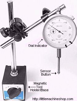
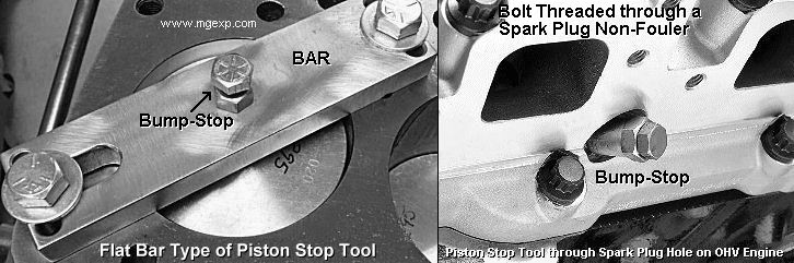 A piston
stop tool is used to accurately find the piston's true Top Dead Center (TDC)
in the engine block. The piston stop tool is always used on the #1 piston,
which is closest to the flywheel on a multi-cylinder air-cooled engine, and
closest to the front of an automotive engine.
A piston
stop tool is used to accurately find the piston's true Top Dead Center (TDC)
in the engine block. The piston stop tool is always used on the #1 piston,
which is closest to the flywheel on a multi-cylinder air-cooled engine, and
closest to the front of an automotive engine.
 A blunt-end
(not to damage the piston) steel rod may need to be welded on the end of
the plug for an extended reach. If a piston pops out of the cylinder at TDC,
then install flat washers as needed so the head will clear the piston at
TDC.
A blunt-end
(not to damage the piston) steel rod may need to be welded on the end of
the plug for an extended reach. If a piston pops out of the cylinder at TDC,
then install flat washers as needed so the head will clear the piston at
TDC.
 To
check and adjust the cam or ignition timing on an OHV (Over Head Valve) engine
with the cylinder head installed on the engine block, a low-cost and simple
bump-stop piston stop tool can be made from a
To
check and adjust the cam or ignition timing on an OHV (Over Head Valve) engine
with the cylinder head installed on the engine block, a low-cost and simple
bump-stop piston stop tool can be made from a
 1-1/8" Diameter Steel Welch
Expansion Plug to block access to governor gear stub shaft. Concaved/dish-shape,
not cupped. OEM Kohler part # X-230-11-S.
1-1/8" Diameter Steel Welch
Expansion Plug to block access to governor gear stub shaft. Concaved/dish-shape,
not cupped. OEM Kohler part # X-230-11-S.
 Kohler K-series Camshaft with
Points Lobe. Fits and designed for Kohler K-series engine models K241, K301,
K321 and K341. Points lobe, lifter lobes, gear teeth and ACR are all in good
condition. The lobes have not been reground for performance. Can be used
in an early K-series engine as an upgrade from the older two-piece camshaft
with the automatic timing advance for easier cranking of engine. Used and
in excellent condition. Discontinued Kohler part #'s 45 010 06-S, 47 010
09-S. (These are basically the same camshafts, just different part
numbers.) $75.00 each, plus shipping & handling. (When
available.)
Kohler K-series Camshaft with
Points Lobe. Fits and designed for Kohler K-series engine models K241, K301,
K321 and K341. Points lobe, lifter lobes, gear teeth and ACR are all in good
condition. The lobes have not been reground for performance. Can be used
in an early K-series engine as an upgrade from the older two-piece camshaft
with the automatic timing advance for easier cranking of engine. Used and
in excellent condition. Discontinued Kohler part #'s 45 010 06-S, 47 010
09-S. (These are basically the same camshafts, just different part
numbers.) $75.00 each, plus shipping & handling. (When
available.) Kohler Magnum Camshaft with
no Points Lobe. Fits and designed for Kohler Magnum engine models M10, M12,
M14 and M16, but can be used in the K-series models K241, K301, K321 and
K341 that have solid state ignition or
Kohler Magnum Camshaft with
no Points Lobe. Fits and designed for Kohler Magnum engine models M10, M12,
M14 and M16, but can be used in the K-series models K241, K301, K321 and
K341 that have solid state ignition or
 For Kohler engine models K241,
M10, K301, M12, K321, M14, K341, M16 and K361. This particular cam profile
design is suitable for heavy lawn and garden work, snow removal, etc., or
stock competition pulling to provide more torque (lugging power) and improved
engine performance from 3,800 to 4,200 RPM. The lobes on this cam are not
welded up. They are professionally and precision reground on a cam grinding
machine to have the factory stock lift (.324"), but with slightly increased
duration, which makes it perform best around 4,000 RPM. This cam will pass
tech for a stock cam. It will add about 3 more horsepower and 2 ft. lbs.
of torque to the average stock engine with more lugging power than the OEM
Kohler K361 cam.
For Kohler engine models K241,
M10, K301, M12, K321, M14, K341, M16 and K361. This particular cam profile
design is suitable for heavy lawn and garden work, snow removal, etc., or
stock competition pulling to provide more torque (lugging power) and improved
engine performance from 3,800 to 4,200 RPM. The lobes on this cam are not
welded up. They are professionally and precision reground on a cam grinding
machine to have the factory stock lift (.324"), but with slightly increased
duration, which makes it perform best around 4,000 RPM. This cam will pass
tech for a stock cam. It will add about 3 more horsepower and 2 ft. lbs.
of torque to the average stock engine with more lugging power than the OEM
Kohler K361 cam.
 This cast cam performs best with our performance
BLUE valve springs (listed below; to
prevent fuel spray out the carburetor and lifter chatter), race-quality retainers
(or the OEM Kohler stamped steel retainers can be used), quality valve job,
ports made larger, and a reworked carburetor with a bored-out venturi for
maximum performance for competition pulling. If there's any restriction of
airflow in and out of the combustion chamber, the cam will not perform at
100% efficiency. This cam builds up the compression about 6% more than the
K361 cam, and approximately 11% more than the flathead engine cams at around
4,000 RPM. This cam sounds just like an OEM Kohler stock cam. You can't hear
the difference out the exhaust. The duration and centerline of the lobes
on this cam helps the engine produce the most power and torque between
3,600-4,500 RPM. At higher RPM, due to the limited duration, no substantial
gain in power or torque will result. If the engine is built to the max, tractor
is geared correctly and traction is adequate, engine shouldn't bog down much
with this cam. It'll keep pumping out the ponies right out the gate! Use
with the OEM Kohler 1" base lifters. When reusing lifters, roughen lifter
faces with 600 grit sandpaper in an erratic pattern to produce a new wear
pattern and so the lifters will rotate slightly with every lift to prevent
wear to the cam lobes. Use the
This cast cam performs best with our performance
BLUE valve springs (listed below; to
prevent fuel spray out the carburetor and lifter chatter), race-quality retainers
(or the OEM Kohler stamped steel retainers can be used), quality valve job,
ports made larger, and a reworked carburetor with a bored-out venturi for
maximum performance for competition pulling. If there's any restriction of
airflow in and out of the combustion chamber, the cam will not perform at
100% efficiency. This cam builds up the compression about 6% more than the
K361 cam, and approximately 11% more than the flathead engine cams at around
4,000 RPM. This cam sounds just like an OEM Kohler stock cam. You can't hear
the difference out the exhaust. The duration and centerline of the lobes
on this cam helps the engine produce the most power and torque between
3,600-4,500 RPM. At higher RPM, due to the limited duration, no substantial
gain in power or torque will result. If the engine is built to the max, tractor
is geared correctly and traction is adequate, engine shouldn't bog down much
with this cam. It'll keep pumping out the ponies right out the gate! Use
with the OEM Kohler 1" base lifters. When reusing lifters, roughen lifter
faces with 600 grit sandpaper in an erratic pattern to produce a new wear
pattern and so the lifters will rotate slightly with every lift to prevent
wear to the cam lobes. Use the
 OEM Kohler Valve Springs designed
specially for Kohler engine models K141, K160/K161, K181,
OEM Kohler Valve Springs designed
specially for Kohler engine models K141, K160/K161, K181,
 OEM Kohler Valve Springs for Kohler K-series and Magnum engine
models K241, M10, K301, M12, K321, M14, K341, M16, K361, K482, K532 and K582.
Each have dampening end to lessen harmonic vibrations at higher RPM. Recommended
for general lawn and garden use. Suitable for up to 3,600± RPM with
cam having stock lift.
OEM Kohler Valve Springs for Kohler K-series and Magnum engine
models K241, M10, K301, M12, K321, M14, K341, M16, K361, K482, K532 and K582.
Each have dampening end to lessen harmonic vibrations at higher RPM. Recommended
for general lawn and garden use. Suitable for up to 3,600± RPM with
cam having stock lift.
 OEM Kohler Valve Spring designed
specially for Kohler KT-series and Magnum engine models MV16, KT17, KT17
Series II, KT19, KT19 Series II, M18, MV18, M20 and MV20. Has no dampening
end. Recommended for general lawn and garden use. Suitable for up to 3,600±
RPM with cam having stock lift. 1-9/16" uncompressed height; use only
with valve rotator. Rotator recommended for exhaust valve to scrape away
any carbon deposits lodged between valve face and seat to prevent valve from
burning.
OEM Kohler Valve Spring designed
specially for Kohler KT-series and Magnum engine models MV16, KT17, KT17
Series II, KT19, KT19 Series II, M18, MV18, M20 and MV20. Has no dampening
end. Recommended for general lawn and garden use. Suitable for up to 3,600±
RPM with cam having stock lift. 1-9/16" uncompressed height; use only
with valve rotator. Rotator recommended for exhaust valve to scrape away
any carbon deposits lodged between valve face and seat to prevent valve from
burning.


 Valve Lifters/Tappets. Replace
worn lifter(s) to prevent erratic valve action and/or premature cam lobe
wear. Non-adjustable; grind end of valve stems with piston positioned at
TDC on compression stroke to set valve clearances.
Valve Lifters/Tappets. Replace
worn lifter(s) to prevent erratic valve action and/or premature cam lobe
wear. Non-adjustable; grind end of valve stems with piston positioned at
TDC on compression stroke to set valve clearances.