 Ignition
Solutions for Older Small Engines and Competition Garden Tractor Pulling
Engines
Ignition
Solutions for Older Small Engines and Competition Garden Tractor Pulling
Engines
Ignition
Solutions for Older Small Engines and Competition Garden Tractor Pulling
Engines
Ignition
Solutions for Older Small Engines and Competition Garden Tractor Pulling
Engines
Educating and Inspiring Small Engine, Lawn & Garden, and Garden
Pulling Tractor Enthusiasts Since 1996. Where Science and Common Sense Come
Together for Safety and Improved Engine/Tractor Performance |
A-1
Miller's Performance Enterprises - Parts & Services
Webstore |  Overstocked Kohler Engine Parts & Cub Cadet Garden Tractor
Parts | Available Soon - Detailed
Illustrated Plans on How to Construct Professional Pulling Sleds
Overstocked Kohler Engine Parts & Cub Cadet Garden Tractor
Parts | Available Soon - Detailed
Illustrated Plans on How to Construct Professional Pulling Sleds
Nowadays, prices are subject to change without notice. Click
Refresh to see any
changes or updates. Optimized for 1152 x 864 computer screen resolution.
To search for a word or phrase in any of my websites, press the CTRL
 and F
and F  keys on
your keyboard simultaneously to open the Find or Search dialog box in your
web browser. And being I have no
apprentice to update and pay for my websites so they'll
continue to be on the Internet, they will be removed forever when I'm no
longer around. Scroll down this website or click/tap the links below to
jump down to...
keys on
your keyboard simultaneously to open the Find or Search dialog box in your
web browser. And being I have no
apprentice to update and pay for my websites so they'll
continue to be on the Internet, they will be removed forever when I'm no
longer around. Scroll down this website or click/tap the links below to
jump down to...
Learn how to precisely set the ignition timing on older Tecumseh engines with points and condenser ignition | How to Set the Ignition Timing on an Engine that has a Flywheel with no Timing Marks |
|||
PerTronix Ignitor Module/Sensors |
FYI - Being we haven't had any Onan or Wisconsin engines in our shop for repairs, we have no experience with working on them. Apparently, these engines are rare in our area (mid-Missouri). Therefore, we do not offer a custom-made electronic ignition conversion kit for these engines. If someone is willing to bring their Onan or Wisconsin engine to us, we're sure we can fabricate and install an electronic ignition system on it. |
 Unsportsmanshiplike Conduct -

 There's a cheater in every sport, and competition tractor
pulling is no different. Honest pullers who ignore the cheater(s) are fools.
And when there's prize money involved, a fool and their money are soon parted.
Anyway, to make competition pulling a fun and fair sport for the entire family,
be protective of your equipment! While at the pulls, keep an eye on your
kill switch pull pin! When a competitive or winning
pulling tractor is left unattended, it's been known that certain disgruntled
pullers
(sore losers
There's a cheater in every sport, and competition tractor
pulling is no different. Honest pullers who ignore the cheater(s) are fools.
And when there's prize money involved, a fool and their money are soon parted.
Anyway, to make competition pulling a fun and fair sport for the entire family,
be protective of your equipment! While at the pulls, keep an eye on your
kill switch pull pin! When a competitive or winning
pulling tractor is left unattended, it's been known that certain disgruntled
pullers
(sore losers  ) belonging
to various associations/clubs, virtually anywhere and everywhere, will pull
a competitor's kill switch pull pin and toss it
out of sight. This is one of the easiest, dishonest and sneaky ways to disable
and sabotage a competitor's tractor. All a cheater needs is an opportunity
in an attempt to gain an advantage on the track. This is also the fastest
way for a pulling association or club to gain a bad reputation and lose honest
pullers. (Bad news travels fast.) This type of behavior doesn't happen often,
but you need to be prepared if or when it does happen. To be prepared for
this unforeseeable extra kill switch pull pin with
you. This kind of dishonest behavior doesn't happen often, but you need to
be prepared if or when it does happen.
Keep an eye on your
carburetor, too! Always try to stay one step ahead of a cheater. Because
there's cheaters in every sport, and nobody likes a cheater, not even cheaters
themselves!
) belonging
to various associations/clubs, virtually anywhere and everywhere, will pull
a competitor's kill switch pull pin and toss it
out of sight. This is one of the easiest, dishonest and sneaky ways to disable
and sabotage a competitor's tractor. All a cheater needs is an opportunity
in an attempt to gain an advantage on the track. This is also the fastest
way for a pulling association or club to gain a bad reputation and lose honest
pullers. (Bad news travels fast.) This type of behavior doesn't happen often,
but you need to be prepared if or when it does happen. To be prepared for
this unforeseeable extra kill switch pull pin with
you. This kind of dishonest behavior doesn't happen often, but you need to
be prepared if or when it does happen.
Keep an eye on your
carburetor, too! Always try to stay one step ahead of a cheater. Because
there's cheaters in every sport, and nobody likes a cheater, not even cheaters
themselves!  But then again, if the
winning tractor is suspected of cheating on the track (illegal fuel, engine,
weight, etc.), there's always the protest rule. But only if it's enforced
by the pulling association. Remember - cheating is devious theft with a sly
smirk. Heck, some pulling associations/clubs vote-in and/or change certain
rules in a meeting during the off-season, lock them in for several years,
but don't even enforce or follow their own rules during the pulling season!
They change their rules so often, they might as well just write them in pencil!
Another thing I don't understand is when a [prominent] puller of an
association/club ask the president of the club if an illegal part can be
used in his engine for pulling, and the president says, "yeah, sure!" But
the pulling association/club's sanctioning rules, the very same rules that
the members (pullers) of the association/club discussed about and voted-on
in a meeting, clearly states in black and white that such a part cannot be
used.
But then again, if the
winning tractor is suspected of cheating on the track (illegal fuel, engine,
weight, etc.), there's always the protest rule. But only if it's enforced
by the pulling association. Remember - cheating is devious theft with a sly
smirk. Heck, some pulling associations/clubs vote-in and/or change certain
rules in a meeting during the off-season, lock them in for several years,
but don't even enforce or follow their own rules during the pulling season!
They change their rules so often, they might as well just write them in pencil!
Another thing I don't understand is when a [prominent] puller of an
association/club ask the president of the club if an illegal part can be
used in his engine for pulling, and the president says, "yeah, sure!" But
the pulling association/club's sanctioning rules, the very same rules that
the members (pullers) of the association/club discussed about and voted-on
in a meeting, clearly states in black and white that such a part cannot be
used.
Ignition Solutions -
 Spark-ignited engines requires
a spark to initiate burning of the air-fuel mixture in the combustion chamber.
The spark in each cylinder is provided by a spark plug and is actually a
flow of electrical current through the air and fuel vapor between the closely
spaced electrodes of the spark plug. The resistance of air is very high.
Therefore, a 20,000 to 30,000 volt potential across the gap is used to fire
the plug. Typically, the ignition system must supply this high voltage from
a 12 volt DC electrical/power source, such as a storage battery. Moreover,
the spark must begin at the proper point in the cycle and must be of sufficient
duration.
Spark-ignited engines requires
a spark to initiate burning of the air-fuel mixture in the combustion chamber.
The spark in each cylinder is provided by a spark plug and is actually a
flow of electrical current through the air and fuel vapor between the closely
spaced electrodes of the spark plug. The resistance of air is very high.
Therefore, a 20,000 to 30,000 volt potential across the gap is used to fire
the plug. Typically, the ignition system must supply this high voltage from
a 12 volt DC electrical/power source, such as a storage battery. Moreover,
the spark must begin at the proper point in the cycle and must be of sufficient
duration.
Whenever a manufacturer wants to sell their latest fancy ignition system, they run a bench test that shows that their unit puts out more voltage than the other guy's. If you read enough ads with claims of extremely high available voltage, you may begin to think that voltage is the only thing necessary to make an ignition system the best in the world. After all, if ignition "A" puts out more voltage than ignition "B", the one you would want is "A", right? Sorry, but that isn't necessarily so. Ignition "A" may put out more voltage, but is it more mechanically dependable than ignition "B"? Did you know that 90% of ignition failures are mechanical and not electrical? Blame burnt, dirty or worn ignition points, defective condenser/capacitor, defective switch(es), broken or chaffed ignition wires, loose screws or connectors, slipped timing, worn hinge/pivot pin hole in ignition points, etc. Apply lubricating grease on the hinge/pivot pin before installing ignition points will help the hole last longer. When the points pivot hole is dry, it'll wear prematurely, effecting ignition timing, resulting in loss of engine horsepower and a poor running engine. By the way - whenever a condenser/capacitor becomes defective or gets weak, the engine may idle well, but hesitate to rev up, or if it does rev up, it may run very erratic (uneven misfire and backfire). For the record, "condenser" is an age old term, and "capacitor" is a newer term for the same device. Ignition capacitors are still commonly called condensers. NOTE: The condenser body must be securely fastened to the engine/chassis ground for the engine to run smooth. If the condenser is loose in its bracket, the bracket can be squeezed slightly with large pliers to be made oblong or egg-shape, and then the condenser will remain tight inside it. But if an engine idles well, but runs erratically above idle, like it hits and misses, pops and backfires, then chances are, it needs a new condenser/capacitor. And always install a condenser with the wire or terminal facing downward so rain water and/or when washing off engine, water will not enter inside condenser, ruining it. With water inside the condenser, this will cause the engine to run erratically when revved up. Or better yet, upgrade/convert the engine with an A-1 Miller's maintenance-free and weather-proof battery-powered flywheel-triggered electronic ignition system for a stronger and more stable spark, quicker starts, smoother idle and overall better running engine.
![]() Ignition coils are small step-up
electrical transformers, increasing 6 or 12 volts from a vehicle's electrical
system up to 20,000 - 40,000 volts to fire the spark plug(s). To make a spark,
the ignition system powers up an individual ignition coil's primary coil
momentarily, creating a powerful magnetic field. It converts or increases
low voltage input in the primary winding to high voltage output in the secondary
winding through a process called induction. There are various designs, but
all ignition coils do the same basic job. The importance of extremely high
secondary voltage for more performance have been somewhat overplayed. An
ignition system, regardless of type, produce only enough voltage necessary
to jump the spark plug gap and ignite the air/fuel mixture. In perfect condition,
a good spark plug wire and high quality copper core/non-resistor spark plug
with a gap of .035" can't handle much more than 32,000 volts. If an ignition
could produce more than that, then the extra voltage would escape through
a leaking spark plug wire, a small crack in the canister ignition coil tower,
etc. Besides, an average engine simply just doesn't need that much voltage.
In most cases, an average engine simply don't need a (40,000 volt)
high-output/performance or OEM automotive electronic ignition coil. If a
plug require only 10,000 volts to jump its gap, then a "Super Coil" that's
advertised to produce 40,000 volts will produce just 10,000 volts for that
same plug under the same conditions. An ignition coil advertised to produce
40,000 volts may have the potential to do it, but unless everything is in
excellent condition, only a fraction of that voltage would reach the spark
plug's tip.
Ignition coils are small step-up
electrical transformers, increasing 6 or 12 volts from a vehicle's electrical
system up to 20,000 - 40,000 volts to fire the spark plug(s). To make a spark,
the ignition system powers up an individual ignition coil's primary coil
momentarily, creating a powerful magnetic field. It converts or increases
low voltage input in the primary winding to high voltage output in the secondary
winding through a process called induction. There are various designs, but
all ignition coils do the same basic job. The importance of extremely high
secondary voltage for more performance have been somewhat overplayed. An
ignition system, regardless of type, produce only enough voltage necessary
to jump the spark plug gap and ignite the air/fuel mixture. In perfect condition,
a good spark plug wire and high quality copper core/non-resistor spark plug
with a gap of .035" can't handle much more than 32,000 volts. If an ignition
could produce more than that, then the extra voltage would escape through
a leaking spark plug wire, a small crack in the canister ignition coil tower,
etc. Besides, an average engine simply just doesn't need that much voltage.
In most cases, an average engine simply don't need a (40,000 volt)
high-output/performance or OEM automotive electronic ignition coil. If a
plug require only 10,000 volts to jump its gap, then a "Super Coil" that's
advertised to produce 40,000 volts will produce just 10,000 volts for that
same plug under the same conditions. An ignition coil advertised to produce
40,000 volts may have the potential to do it, but unless everything is in
excellent condition, only a fraction of that voltage would reach the spark
plug's tip.
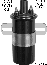
Most self-energizing magneto and battery-powered stock ignition coils, regardless of size, typically produce around 20,000 volts, suitable for stock engines burning gas with plug gaps of .025" - .035". High-performance coils, depending on the manufacturer, produce roughly 30,000 to 60,000 volts, allowing for wider plug gaps of .045"- .060" for a more thorough combustion (especially with methanol fuel), higher RPM, and reduced spark plug fouling. However, it's important that a metal core/non-suppression spark plug wire and copper core/non-resistor spark plug be used with virtually any coil to reduce the chance of the secondary windings from burning up, resulting in a failed coil.
As a spark plug's electrodes wear, its gap increases, so more voltage is required from the ignition coil before the spark is able to jump across the gap. If uncorrected, the gap eventually increases to the point where the plug requires more voltage than the coil can produce. However, a (40,000 volt) high-output/performance or OEM automotive electronic ignition coil would probably be able to fire the worn plug. Did you know that most stock ignition coils will produce enough voltage to jump a gap of up to 3/4 of an inch? Of course, no spark plug electrode will ever wear that wide. Therefore, the use of a (40,000 volt) high-output/performance or OEM automotive electronic ignition coil really isn't necessary, except in extreme high compression, alcohol-burning engines.
Actually, virtually all ignition systems, rather it's a magneto type with points and condenser, solid state with an electronic module, battery ignition with points and condenser, or battery-powered electronic ignition, is capable of producing much more voltage that is necessary to make an average engine run well. And the compression ratios in most engines will not allow a standard-output coil or a high-output/performance coil produce maximum voltage under the conditions it's operating under. Because metal core spark plug wire(s) and non-resistor/copper core spark plug(s) allow the coil to operate at low voltage, while suppression/carbon core spark plug wire(s) and resistor-type spark plug(s) will force the coil to operate at higher voltage. This is why any automobile with electronic ignition, and suppression/carbon core spark plug wire(s) with resistor-type spark plug(s) require a high-output coil, and older vehicles with points and condenser, and metal core spark plug wire(s) with non-resistor/copper-core spark plug(s) can use a standard-output coil. Using a high-output/performance coil with metal core spark plug wire(s) and non-resistor/copper-core spark plug(s) would be overkill, because the coil would never reach its maximum voltage that it's designed for, and using a standard-output coil with suppression/carbon core spark plug wire(s) and resistor-type spark plug(s) would allow the coil to operate at a much higher voltage at all times, which could possibly shorten the life of the coil due to overheating of the secondary windings within the coil.
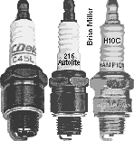
What are the Best Spark Plugs to Use for an Ordinary Lawn & Garden Tractor Engine or Competition Garden Pulling Tractor Engine? [Return to previous paragraph, section or website]
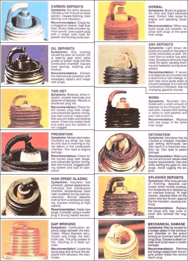
 After
thorough testing and research, I've found that engine dyno tests have proven
that Autolite copper core spark plugs make the most power. Champion copper
core were second, and AC Delco copper core was third. NGK copper core made
the least power. The Autolite, Champion and AC Delco copper core spark plugs
are of the best quality, and without a doubt, when used with a metal core
spark plug wire, will allow the ignition coil to last much longer. These
do not foul-out prematurely and they seem to last a long time. Also, it'll
be a good idea to avoid using resistor type spark plug wires and resistor-type
spark plugs in a small engine with self-energizing magneto or solid state
electronic ignition. Resistor plugs may cause a good magneto or solid state
electronic ignition coil/module to go bad prematurely because they force
the secondary windings within the coil to produce higher voltage than usual
to fire the plug, eventually causing the windings to burn out.
After
thorough testing and research, I've found that engine dyno tests have proven
that Autolite copper core spark plugs make the most power. Champion copper
core were second, and AC Delco copper core was third. NGK copper core made
the least power. The Autolite, Champion and AC Delco copper core spark plugs
are of the best quality, and without a doubt, when used with a metal core
spark plug wire, will allow the ignition coil to last much longer. These
do not foul-out prematurely and they seem to last a long time. Also, it'll
be a good idea to avoid using resistor type spark plug wires and resistor-type
spark plugs in a small engine with self-energizing magneto or solid state
electronic ignition. Resistor plugs may cause a good magneto or solid state
electronic ignition coil/module to go bad prematurely because they force
the secondary windings within the coil to produce higher voltage than usual
to fire the plug, eventually causing the windings to burn out.
A coil can show good spark in the open atmosphere and the engine may idle well, but when the throttle is opened up, which builds up the more air pressure within the combustion chamber, the higher compression will literally blow out the spark, causing the engine to die out. This can cause the secondary windings in the coil to burn out if a new spark plug (or spark plug wire) is not installed.
And unlike gasoline, alcohol fuels (ethanol and methanol) will rarely foul spark plugs. Also, depending on which type of gas is burned in a competition pulling engine, use only the type of spark that's recommended by the manufacturer of the engine, even if it's a high-performance engine. If the wrong or a different type of plug is used, the engine might lose power, run erratically or may not start.
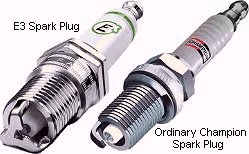 The
E3 Spark Plug -
The
E3 Spark Plug -
When using E3 spark plugs, for a stronger spark, use the copper core/non-resistor E3 spark plug(s), index it/them with the open gap facing the center of the piston, and use a high capacity/performance ignition condenser/capacitor with a (40,000 volt) high-output/performance or OEM automotive electronic ignition coil to produce a stronger spark for better engine performance. FYI - The blue color is made by burning of nitrogen and oxygen in the atmosphere when they are energized, and the snapping sound is breaking of the sound barrier resulting in a very tiny sonic boom released from the rapid burning and explosion of the nitrogen and oxygen.
And avoid using low cost, inferior quality or "cheapie" spark plugs! Personally,
before installing the [correct type of] this spark plug in a B&S lawn
mower engine, to remove all doubts about the strength of the ignition system,
I checked to verify if it has a strong, snappy
blue spark, which it would have. FYI - The blue color is made
by burning of nitrogen and oxygen in the atmosphere when they are energized,
and the snapping sound is breaking of the sound barrier, resulting in a very
tiny
sonic boom released from the rapid burning and explosion
of the nitrogen and oxygen. Then after setting the correct gap and installing
the plug in the engine, the first time when priming the carburetor with gas
and cranking the engine to get it started, to my surprise, it would foul-out
(develop a weak, white spark)! And if the engine did start, it would only
run for a few seconds before another new plug of this brand became fouled.
I've had this happen with every spark plug of this brand! These spark
plugs have also been known to cause a good ignition coil to fail prematurely,
too! I hate to say this about a product that many claim to be superior, but
it's the honest truth. They say that seeing is believing, and I believe this
product to be inferior. If anyone have good results using this brand of spark
plug, perhaps they should purchase a winning lottery ticket, too.
 [Return
to previous paragraph, section or website]
[Return
to previous paragraph, section or website]
What Exactly is Coil Saturation?
Basically speaking, full coil saturation is when the ignition points and condenser (or two condensers) or electronic ignition control module/unit (ICU) can deliver more voltage to the coil so it will produce a stronger spark. While electricity itself moves extremely fast, it takes time for the changing magnetic fields in a coil to develop the full potential current and voltage. In other words, electricity moves much faster than magnetism. This is a way of saying that the induced voltage (stepped up voltage) does not develop instantaneously. To keep things simple, think of the coil as an energy storage device that can be "charged up" and "discharged" in a manner similar to a battery. It takes time for the magnetic field of the secondary windings in the coil to "charge" at full RPM, a condition that is called coil saturation. Similarly, it takes time for the coil to discharge some quantity of its electrical energy as it fires a spark plug. It takes more voltage from a condenser/capacitor or virtually any electronic ignition control unit (ICU) through the primary windings within the coil to make the magnetic field stronger to produce more voltage for the secondary windings to fire the spark plug(s) at higher RPM. This helps an engine to rev up at higher RPM. When maximum current flow is present in a winding, a maximum magnetic field is present and the coil winding is considered saturated. Saturation of the primary windings only occurs if the ignition primary switching device provides a ground path long enough to allow maximum current flow (5.5 amps maximum). If a low capacity condenser/capacitor or standard ICU is used, insufficient amount of magnetic field will be induced in the secondary winds, and the engine may idle well, but as it revs up, due to the higher compression [as the throttle plate is opened more], the (weak) spark at the spark plug's tip literally gets "blown out", and the engine fails to rev up. Due to coil saturation, certain coils require two medium capacity [Kohler] ignition condensers/capacitors, or one high capacity/performance condenser/capacitor to absorb the full saturation (voltage) of the primary windings within the coil. Go here for more information: Saturation (magnetic). [Return to previous paragraph, section or website]
In most cases, if an engine is kept in perfect tune, the factory stock ignition system provide more than enough voltage for the average competition garden pulling tractor. Most conventional stock ignitions are designed to provide a strong spark up to a relatively low engine speed. With Kohler engines running in modified form, they will get up as high as 9,000 RPM. But at open RPM (wide open throttle) with the ignition points system, the points open and close so quickly that the coil's primary winding has less time to absorb voltage. This means the condenser/capacitor doesn't have enough time to rebuild the capacitance discharge. As a result, with the stock system, secondary voltage to the plug decreases and the engine won't run at open speed (wide open throttle) or it may sputter just when victory is in sight. However, for most competition garden pulling tractors, a stock ignition system that's in good condition will provide plenty of spark. NOTE: The condenser body must be securely fastened to the engine/chassis ground for the engine to run smooth. If the condenser is loose in its bracket, the bracket can be squeezed slightly with large pliers to be made oblong or egg-shape, and then the condenser will remain tight inside it. But if an engine idles well, but runs erratically above idle, like it hits and misses, pops and backfires, then chances are, it needs a new condenser/capacitor. And always install a condenser with the wire or terminal facing downward so rain water and/or when washing off engine, water will not enter inside condenser, ruining it. With water inside the condenser, this will cause the engine to run erratically when revved up. Or better yet, upgrade/convert the engine with an A-1 Miller's maintenance-free and weather-proof battery-powered flywheel-triggered electronic ignition system for a stronger and more stable spark, quicker starts, smoother idle and overall better running engine.
There are 5 types of ignition systems that's used on all small gas engines, rather if it's a 2- or 4-cycle engine:
 ) setting (make sure the battery is fully charged)
or a
self-powered test light in the ignition points only (the
points will act as a switch) or a strobe timing
light (with the engine running) to set the ignition timing on a magneto
system, but a 12 volt battery must be available to power the timing light.
The timing light connects to the battery and spark plug wire. Because of
their compactness and no need for an outside electrical source, magneto ignition
is very popular on virtually all small engine equipment. Such as gas-powered
string trimmers, chainsaws, lawn mowers, garden tillers, go-karts, riding
mowers, lawn tractors, lawn & garden tractor, small motorized vehicle
and small construction equipment engines. The major components of the magneto
ignition system include: coil, points and condenser.
How
magneto coils generate a spark.
) setting (make sure the battery is fully charged)
or a
self-powered test light in the ignition points only (the
points will act as a switch) or a strobe timing
light (with the engine running) to set the ignition timing on a magneto
system, but a 12 volt battery must be available to power the timing light.
The timing light connects to the battery and spark plug wire. Because of
their compactness and no need for an outside electrical source, magneto ignition
is very popular on virtually all small engine equipment. Such as gas-powered
string trimmers, chainsaws, lawn mowers, garden tillers, go-karts, riding
mowers, lawn tractors, lawn & garden tractor, small motorized vehicle
and small construction equipment engines. The major components of the magneto
ignition system include: coil, points and condenser.
How
magneto coils generate a spark.
 the spark plug gap can be set
at .035" for a stronger spark. Also, the [magneto] Off-Ignition-Start key
switch will need to be changed to an OFF-ON-START key switch that's designed
for battery ignition. Or, an OFF-ON toggle switch or
OFF-ON rotary key switch, or an OFF-ON-START rotary key switch to power
the ignition and a push button starter switch to energize the solenoid/starter
motor can be used instead. And with battery ignition, the engine will need
a reliable charging system to keep the battery fully charged to crank the
engine and so the ignition will produce a strong
spark. When converting to battery ignition, remove or disconnect the
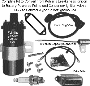
magneto coil and condenser/capacitor first. Please click
here if you need a kit to convert
an engine to the battery ignition system.
the spark plug gap can be set
at .035" for a stronger spark. Also, the [magneto] Off-Ignition-Start key
switch will need to be changed to an OFF-ON-START key switch that's designed
for battery ignition. Or, an OFF-ON toggle switch or
OFF-ON rotary key switch, or an OFF-ON-START rotary key switch to power
the ignition and a push button starter switch to energize the solenoid/starter
motor can be used instead. And with battery ignition, the engine will need
a reliable charging system to keep the battery fully charged to crank the
engine and so the ignition will produce a strong
spark. When converting to battery ignition, remove or disconnect the
magneto coil and condenser/capacitor first. Please click
here if you need a kit to convert
an engine to the battery ignition system.
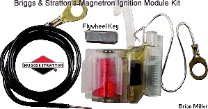 B&S's
Magnetron™ electronic ignition sensor/module (only for two-post coils), or
a universal electronic transistorized ignition
module (for two- or three-armature coils).
B&S's
Magnetron™ electronic ignition sensor/module (only for two-post coils), or
a universal electronic transistorized ignition
module (for two- or three-armature coils).
 Transistorized Ignition is the combination of an analog
(electrical/mechanical) and digital (100% electronic) ignition system with
breaker points. The components of the transistorized ignition system include:
points, coil and electronic control module. All transistorized ignition systems
requires 12 volts DC negative ground of power. They produce a
strong spark, and allow the ignition points
to last longer, perhaps the life of the engine, and it requires no
condenser/capacitor. It requires a 12 volt DC source (battery) to power the
system.
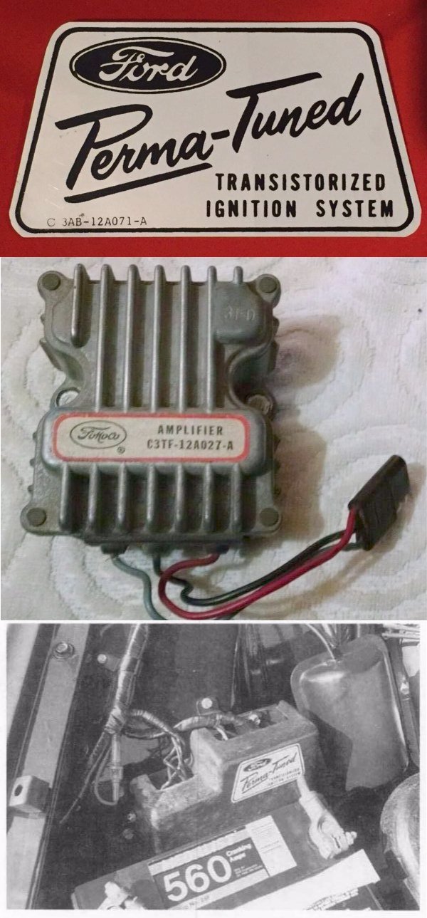
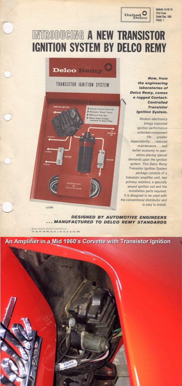
Ford Motor Company's transistorized ignition system was
originally offered on various Ford vehicles from 1965 to 1972, which is no
longer available. GM also offered the transistorized ignition on certain
Corvette vehicles. (Click the photos to the right -> for a larger view
of each.) MSD
Performance also offers a transistorized breaker point ignition module
that allow the ignition points to last longer. Two things to take into
consideration about using a transistorized breaker point ignition system
is if an engine sits for a long period of time, the ignition points contacts
may become oxidized because there's not enough electrical current or "spark"
that occurs between the contacts to burn away the oxidation. Another drawback
is being the transistorized breaker point ignition system requires mechanical
operation of the ignition points. If the ignition points lobe on the [Kohler]
camshaft is worn or becomes worn overtime, this would retard the ignition
timing severely, resulting in hard starting and loss of engine power. There
is no way to avoid this except to install a threaded-on stainless steel nut
on one end of the OEM points pushrod for contact of the unworn sides of the
points lobe, or convert the engine to A-1 Miller's custom-made and reliable
flywheel-triggered 12 volt electronic
ignition. There are also ignition products called the Transdenser II
and PointSaver (which are fine products), which will NOT prevent the points
lobe on the camshaft from possibly wearing, which will eventually retard
the ignition timing. Besides, connecting a 1.8 ohm (maximum size available)
ballast
resistor to the coil with a 3.0 ohm primary resistor or using a 4.0
ohm coil will basically do the same as the Transdenser II and PointSaver.
The ballast resistor will send less current through the points to prevent
excessive burning or wearing of the contacts. The coil will still produce
a very strong spark. By the way - A-1 Miller's
custom-made electronic ignition systems
are 100% digital and doesn't use points or the mechanical operation of the
points lobe.
Transistorized Ignition is the combination of an analog
(electrical/mechanical) and digital (100% electronic) ignition system with
breaker points. The components of the transistorized ignition system include:
points, coil and electronic control module. All transistorized ignition systems
requires 12 volts DC negative ground of power. They produce a
strong spark, and allow the ignition points
to last longer, perhaps the life of the engine, and it requires no
condenser/capacitor. It requires a 12 volt DC source (battery) to power the
system.
Ford Motor Company's transistorized ignition system was
originally offered on various Ford vehicles from 1965 to 1972, which is no
longer available. GM also offered the transistorized ignition on certain
Corvette vehicles. (Click the photos to the right -> for a larger view
of each.) MSD
Performance also offers a transistorized breaker point ignition module
that allow the ignition points to last longer. Two things to take into
consideration about using a transistorized breaker point ignition system
is if an engine sits for a long period of time, the ignition points contacts
may become oxidized because there's not enough electrical current or "spark"
that occurs between the contacts to burn away the oxidation. Another drawback
is being the transistorized breaker point ignition system requires mechanical
operation of the ignition points. If the ignition points lobe on the [Kohler]
camshaft is worn or becomes worn overtime, this would retard the ignition
timing severely, resulting in hard starting and loss of engine power. There
is no way to avoid this except to install a threaded-on stainless steel nut
on one end of the OEM points pushrod for contact of the unworn sides of the
points lobe, or convert the engine to A-1 Miller's custom-made and reliable
flywheel-triggered 12 volt electronic
ignition. There are also ignition products called the Transdenser II
and PointSaver (which are fine products), which will NOT prevent the points
lobe on the camshaft from possibly wearing, which will eventually retard
the ignition timing. Besides, connecting a 1.8 ohm (maximum size available)
ballast
resistor to the coil with a 3.0 ohm primary resistor or using a 4.0
ohm coil will basically do the same as the Transdenser II and PointSaver.
The ballast resistor will send less current through the points to prevent
excessive burning or wearing of the contacts. The coil will still produce
a very strong spark. By the way - A-1 Miller's
custom-made electronic ignition systems
are 100% digital and doesn't use points or the mechanical operation of the
points lobe.
By the way - for a pulling tractor that has an engine-mounted starter motor but no charging system, it's best to use a quality-made automotive battery in the tractor. Not only because an automotive battery holds its charge longer to crank even the highest compression engine after several pulls, they can provide plenty of energy to a battery-powered ignition system for a stronger spark for better engine performance.
Information about Ignition Coils -
 Some ignition coils have an internal resistor, while others
rely on an external ballast resistor (normally
white ceramic block 3 to 4 inches long) or a resistor wire (in the wiring
circuit) to limit the current flowing through the primary windings within
the coil from the 12-volt electrical/power source. Various standard-output/stock
ignition coils and most (40,000 volt) high-output/performance or OEM automotive
electronic ignition coils require a minimum 1.5 ohm
ballast resistor (originally came on all 1955-57
General Motors vehicles, all 1953-85 Chrysler, Dodge and Plymouth (MOPAR)
vehicles, various 1956-75 Ford, Lincoln and Mercury vehicles, including various
makes and models of other older vehicles) or a GM or Ford full-length ignition
resistor wire when used with a ignition points and condenser/capacitor ignition
system to prevent excessive burning of the ignition points contacts. The
1.4± ohm voltage-reducing wire came on all 1958-74 GM vehicles and various
1969-91 Ford vehicles, and connects between the ignition terminal on the
fuse block to the positive (+) coil terminal. A
ballast resistor or ignition resistor wire
is basically a voltage reducer that reduces 12 volts down to anywhere between
8 to 10-1/2 volts, depending on the load.
Some ignition coils have an internal resistor, while others
rely on an external ballast resistor (normally
white ceramic block 3 to 4 inches long) or a resistor wire (in the wiring
circuit) to limit the current flowing through the primary windings within
the coil from the 12-volt electrical/power source. Various standard-output/stock
ignition coils and most (40,000 volt) high-output/performance or OEM automotive
electronic ignition coils require a minimum 1.5 ohm
ballast resistor (originally came on all 1955-57
General Motors vehicles, all 1953-85 Chrysler, Dodge and Plymouth (MOPAR)
vehicles, various 1956-75 Ford, Lincoln and Mercury vehicles, including various
makes and models of other older vehicles) or a GM or Ford full-length ignition
resistor wire when used with a ignition points and condenser/capacitor ignition
system to prevent excessive burning of the ignition points contacts. The
1.4± ohm voltage-reducing wire came on all 1958-74 GM vehicles and various
1969-91 Ford vehicles, and connects between the ignition terminal on the
fuse block to the positive (+) coil terminal. A
ballast resistor or ignition resistor wire
is basically a voltage reducer that reduces 12 volts down to anywhere between
8 to 10-1/2 volts, depending on the load.
According to the extensive research I've performed, the primary ohm
() resistance in the most common battery-powered
ignition coils are as follows:
Most canister-type ignition coils appear the same on the outside. If a coil reads "12 VOLTS" on its casing, this doesn't necessary mean that it's for a 12 volt ignition system. Some coils may read 12 VOLTS, but it's actually for a 6 volt ignition system. (Mislabeled coil.) Therefore, it's best to test the coil's internal primary ohm resistance to make sure.
To test for continually of an ignition coil (to see if it's in good condition),
use a multimeter set on the ohm () resistance.
To test the secondary winding (this is the one that usually burns out), insert
one of the multimeter's probes into the spark plug terminal of the coil,
contacting the metal inside the terminal. And touch the second probe of the
meter to the ignition coil's negative (–) terminal. (This is the one
not connected to the primary winding and resistor.) Depending on the type
of coil (magneto, compact, standard size or high output/performance), the
meter should read 6,000 to 15,000 ohms. If it does not, the secondary winding
is faulty and the coil needs to be replaced.
A ballast resistor may not be needed with
many new coils because most of them nowadays have an internal resistor. But
with A-1 Miller's flywheel- or
crank-trigger electronic ignition, a
coil without an internal resistor, rather if it's a standard-output/stock
or (40,000 volt) high-output/performance or OEM automotive electronic ignition
coil, is required to produce full volts to the spark plug. And using a resistor
effects the voltage output of the coil very little. It only prevents premature
burning of the ignition points contacts. The reason manufacturers don't install
a resistor inside some (40,000 volt) high-output/performance or OEM automotive
electronic ignition coils is because these coils draw more amps from the
battery or charging system. Most stock/standard output coils draws approximately
3 amps, and most (40,000 volt) high-output/performance or OEM automotive
electronic ignition coil can draw up to 6 amps under full compression. This
cause the resistor to operate at a higher temperature, which could overheat
and damage the windings within the coil. If a (40,000 volt)
high-output/performance or OEM automotive electronic ignition coil is preferred,
when purchasing one, be sure to ask the salesperson if it have an internal
resistor or if it requires an external resistor. This is important for the
life of the ignition points. The absence of the resistor will, without a
doubt, increase voltage to the spark plugs, and will likely reduce the life
of the ignition points in a mechanical ignition points ignition system.
 The plastic lever that one half
of the ignition points contacts is fasten to could also melt or become deformed
due to the excessive heat from the high voltage going through the ignition
points in absence of a ballast resistor. This
especially happens when a
GM DIS (Distributorless Ignition System) coil or a 6 volt
coil is used in a 12 volt system without a 1.6 ohm
ballast resistor connected to reduce the voltage.
And a (40,000 volt) high-output/performance or OEM automotive electronic
ignition coil has no effect whatsoever with A-1 Miller's
flywheel- or
crank-trigger electronic ignition when
using a GM 4-pin HEI
(High
Energy Ignition), Chrysler (w/ballast resistor) or
Ford electronic ignition control module/unit (ICU).
But the Chrysler control module requires a ballast resistor to prevent from
burning up. Also, most stock coils produce more than enough voltage when
used with even the hottest high-performance engines, especially with A-1
Miller's flywheel- or
crank-trigger electronic ignition. And
the ohm resistance value of most common ballast resistors used for ignition
systems come in: 0.8, 1.2, 1.3, 1.4, 1.5, 1.6 and 1.8. Keep in mind when
testing a coil or ballast resistor, the
resistance can vary more or less (±) by 1.0 ohm.
The plastic lever that one half
of the ignition points contacts is fasten to could also melt or become deformed
due to the excessive heat from the high voltage going through the ignition
points in absence of a ballast resistor. This
especially happens when a
GM DIS (Distributorless Ignition System) coil or a 6 volt
coil is used in a 12 volt system without a 1.6 ohm
ballast resistor connected to reduce the voltage.
And a (40,000 volt) high-output/performance or OEM automotive electronic
ignition coil has no effect whatsoever with A-1 Miller's
flywheel- or
crank-trigger electronic ignition when
using a GM 4-pin HEI
(High
Energy Ignition), Chrysler (w/ballast resistor) or
Ford electronic ignition control module/unit (ICU).
But the Chrysler control module requires a ballast resistor to prevent from
burning up. Also, most stock coils produce more than enough voltage when
used with even the hottest high-performance engines, especially with A-1
Miller's flywheel- or
crank-trigger electronic ignition. And
the ohm resistance value of most common ballast resistors used for ignition
systems come in: 0.8, 1.2, 1.3, 1.4, 1.5, 1.6 and 1.8. Keep in mind when
testing a coil or ballast resistor, the
resistance can vary more or less (±) by 1.0 ohm.
How to Test a Battery-Powered Ignition Coil to Find if it's in Good Condition to Produce a Strong Spark -
First of all, the armature or metal casing on a battery-powered ignition
coils do not need to be connected to the engine or chassis ground (which
connects to the negative (–) battery post). And on a battery-powered
ignition coil, the primary windings is connected from the positive (+) terminal
(which connects to the positive (+) battery post), and the coil negative
(–) terminal connects to the ignition points and condenser. The ignition
points and condenser must be grounded to the engine or chassis (which connects
to the negative (–) battery post). The primary windings is also connected
through an internal resistor to the secondary windings and to the spark plug,
which is grounded. This is how coils complete the circuit to make a spark.
One way to test the primary windings in a coil to find if it's in good condition
is with a
digital multimeter (DMM, DVOM) and for the most accurate
reading, select the 200 ohm () setting. On most
digital multimeters, resistance is denoted by the capital Greek letter Omega
(), which stand for ohm. (Named after
Georg ohm.) IMPORTANT - For an accurate reading, make
sure the battery in the digital multimeter is fully charged, and the digital
multimeter and the part to be tested are warmed to room temperature (72°F).
The accuracy of testing a coil is more complicated when performed with an
analog multimeter. But not all coils will test good
this way! With certain coils, the secondary windings will show no resistance,
which will be a false indication that it's a defective coil. Therefore, the
best way to test a coil to find if it's in good condition to produce a strong
spark is to connect it in an ignition system or bench test it. To bench test
a coil, use three jumper wires with alligator clips, a fully charged 12 volt
battery, a battery-powered ignition condenser, and preferably a metal core
spark plug wire and a known good spark plug. Ignition points are not required
and is irrelevant in performing this type of test. Connect the wires as follows,
then observe for spark:
Metal Core Spark Plug Wires VS Suppression/Carbon Core Spark Plug Wires, and Non-Resistor/Copper Core Spark Plugs VS Resistor-Type Spark Plugs - (Added 2/26/20)
 Copper or metal core spark
plug wires provide 100% voltage to the spark plug at all times for a strong,
blue spark to thoroughly burn the fuel in the combustion chamber! Most OEM
automotive or brightly-colored coil-to-spark plug wires have a suppression/carbon
core, which deliver about 40%-50% voltage to the spark plug at peak demand,
which is at wide open throttle engine operation. Anyway, when testing the
resistance of a metal core spark plug wire versus a suppression/carbon core
spark plug wire with an ohm meter, the meter will show no resistance with
the metal core wire, but it will show about half (40%-50%) of resistance
with a suppression/carbon core wire. It takes about 10,000-12,000 volts to
fire the average spark plug in an engine when under a heavy load at wide
open throttle. Therefore, most (40,000 volt) high-output/performance or OEM
automotive electronic ignition coils that produce a minimum of 30,000 volts,
like the ones used in most automobiles, are able to fire a [quality made]
suppression/carbon core spark plug wire and a resistor-type spark plug with
no problem, because only about half the voltage from the coil goes through
the wire and to the plug. But if a [quality made] suppression/carbon core
spark plug wire and a resistor-type spark plug is used with a standard output
ignition coil that produce 20,000-20,000 volts, like the ones used on most
small engines and early automobiles with point ignition, it may not be able
to successfully fire the plug under full compression (wide open throttle),
and the engine may misfire. This is why ALL magneto/solid state small engine
armature ignition coils and early automobiles with point ignition use metal
core spark plug wires and a coil-to-distributor wire, and Kohler uses metal
core spark plug wire(s) with a compact- or standard-size canister ignition
coil. If a metal core spark plug wire and copper core/non-resistor spark
plug is used with a (40,000 volt) high-output/performance or OEM automotive
electronic ignition coil, will only produce 10,000-12,000 to fire the plug.
It will NEVER produce the maximum voltage it was designed for through the
metal core wire and copper core plug. even when the engine is under a heavy
load at wide open throttle. Only most factory automotive engines since 1974
with electronic ignition use a high-output coil, suppression/carbon core
spark plug wires and resistor-type spark plugs. The reason suppression/carbon
core spark plug wires and resistor-type spark plugs are used is because these
eliminate high frequency radio-air-waves, which cause static (rapid
tick-tick-tick sound) on most in-car radios and TVs with an antenna when
you drive by a house. Single- or twin-cylinder small engines with only one
or two metal core spark plug wires don't produce enough radio-air-waves to
cause static on most radios and TVs. When used often, it's a well-known fact
that most suppression/carbon core spark plug wires deteriorate or "break
down" overtime. They lose their ability to maintain maximum voltage to the
spark plug(s), even when used with a (40,000 volt) high-output/performance
or OEM automotive electronic ignition coil. But a metal core spark plug wire
will never lose voltage. It will last indefinitely. Many competition pullers
that use a [fancy appearing, brightly-colored] suppression/carbon core spark
plug wire really believe they're going to go further down the track, when
actually they're just defeating the purpose.
Copper or metal core spark
plug wires provide 100% voltage to the spark plug at all times for a strong,
blue spark to thoroughly burn the fuel in the combustion chamber! Most OEM
automotive or brightly-colored coil-to-spark plug wires have a suppression/carbon
core, which deliver about 40%-50% voltage to the spark plug at peak demand,
which is at wide open throttle engine operation. Anyway, when testing the
resistance of a metal core spark plug wire versus a suppression/carbon core
spark plug wire with an ohm meter, the meter will show no resistance with
the metal core wire, but it will show about half (40%-50%) of resistance
with a suppression/carbon core wire. It takes about 10,000-12,000 volts to
fire the average spark plug in an engine when under a heavy load at wide
open throttle. Therefore, most (40,000 volt) high-output/performance or OEM
automotive electronic ignition coils that produce a minimum of 30,000 volts,
like the ones used in most automobiles, are able to fire a [quality made]
suppression/carbon core spark plug wire and a resistor-type spark plug with
no problem, because only about half the voltage from the coil goes through
the wire and to the plug. But if a [quality made] suppression/carbon core
spark plug wire and a resistor-type spark plug is used with a standard output
ignition coil that produce 20,000-20,000 volts, like the ones used on most
small engines and early automobiles with point ignition, it may not be able
to successfully fire the plug under full compression (wide open throttle),
and the engine may misfire. This is why ALL magneto/solid state small engine
armature ignition coils and early automobiles with point ignition use metal
core spark plug wires and a coil-to-distributor wire, and Kohler uses metal
core spark plug wire(s) with a compact- or standard-size canister ignition
coil. If a metal core spark plug wire and copper core/non-resistor spark
plug is used with a (40,000 volt) high-output/performance or OEM automotive
electronic ignition coil, will only produce 10,000-12,000 to fire the plug.
It will NEVER produce the maximum voltage it was designed for through the
metal core wire and copper core plug. even when the engine is under a heavy
load at wide open throttle. Only most factory automotive engines since 1974
with electronic ignition use a high-output coil, suppression/carbon core
spark plug wires and resistor-type spark plugs. The reason suppression/carbon
core spark plug wires and resistor-type spark plugs are used is because these
eliminate high frequency radio-air-waves, which cause static (rapid
tick-tick-tick sound) on most in-car radios and TVs with an antenna when
you drive by a house. Single- or twin-cylinder small engines with only one
or two metal core spark plug wires don't produce enough radio-air-waves to
cause static on most radios and TVs. When used often, it's a well-known fact
that most suppression/carbon core spark plug wires deteriorate or "break
down" overtime. They lose their ability to maintain maximum voltage to the
spark plug(s), even when used with a (40,000 volt) high-output/performance
or OEM automotive electronic ignition coil. But a metal core spark plug wire
will never lose voltage. It will last indefinitely. Many competition pullers
that use a [fancy appearing, brightly-colored] suppression/carbon core spark
plug wire really believe they're going to go further down the track, when
actually they're just defeating the purpose.
Self-energizing small engine magneto armature
ignition coils and battery-powered coils with either points and condenser
or electronic ignition must be used with a metal core spark plug wire and
a copper core/non-resistor spark plug. Most automobiles with electronic ignition
have
suppression/carbon core spark plug wires only to prevent
interference of sensitive electronic components and [AM/FM] radio static.
However, if a suppression/carbon core spark plug wire and/or a
resistor type spark plug is used with a magneto
or battery-powered ignition coil, the coil may operate at a much higher than
normal temperature (too hot to the touch), and either the coil will fail
or the engine will idle well, but hesitate to rev up at high RPM due to the
high resistance in the suppression/carbon core spark plug wire and/or a
resistor
type spark plug. And avoid using a
suppression/carbon core spark plug wire with an electronic
ignition system on a small engine! The reason being is if the suppression/carbon
core spark plug wire becomes extremely weak and deteriorated with very high
resistance, this can cause the ignition coil and possibly the electronic
ignition control module to burn up.
How to Test the Strength of an Ignition Coil -
First of all, I think the
inline ignition spark plug tester that connects between
the spark plug and spark plug wire should not be used to test for spark!
(Personally, I think this is the most ridiculous spark tester I have ever
seen.) The reason being is if the spark plug itself is defective, the
inline ignition spark plug tester will show a false indication
that the entire ignition system is malfunctioning. And a good spark plug
will show only if the ignition system is working or not. It will not show
the strength of the ignition system or ignition coil. Therefore, a simple
and accurate way to test for spark (and/or the condition of the spark plug)
is to remove the spark plug, reattach the spark plug wire on the spark plug,
place the spark plug on a bare metal part of the engine or chassis so it'll
make good contact, then crank the engine and at the same time, observe for
spark at the spark plug's tip. (May have to perform this test in the shade
because it may be hard to see the spark in bright sunlight.) An ignition
system in good condition is supposed to produce a strong, snappy
blue spark. FYI - The blue color is
made by burning of nitrogen and oxygen in the atmosphere when they are energized,
and the snapping sound is breaking of the sound barrier resulting in a very
tiny
sonic boom released from the rapid burning and explosion
of the nitrogen and oxygen. If the spark is visibly white or
red in color, either the spark plug is
fouled (from excessive raw fuel or oil burning) or has deteriorated (from
excessive use), the ignition points contacts are burnt or dirty,
suppression/carbon core spark plug wire has deteriorated (if used), or the
ignition coil may be weak and needs replacing.
 To
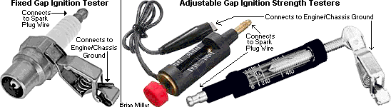
test the strength of the ignition system, it's best use either a
fixed ignition spark tester or an adjustable ignition strength
tester, like the ones in the photo to the right ->. These connect
between the spark plug wire and engine/chassis ground. The fixed ignition
spark tester works great for self-energizing magneto and solid state electronic,
and battery-powered ignition systems with a standard-output/stock coil to
see if the ignition system is adequate to make a
strong spark, but the adjustable ignition
strength tester can be used to test and measure the voltage output of the
ignition coil. The spark of a typical self-energizing magneto or solid state
electronic ignition system in excellent condition will jump a gap of
approximately 5/8" (10,000-12,000 volts), and the spark of a typical
battery-powered ignition points/condenser, crank-trigger or flywheel-triggered
electronic ignition systems with a standard-output/stock coil in excellent
condition will jump a gap of approximately 3/4" (20,000 volts), but the spark
of a typical battery-powered ignition points/condenser, crank-trigger or
flywheel-triggered electronic ignition systems with a (40,000 volt)
high-output/performance or OEM automotive electronic ignition coil in excellent
condition will jump a gap of approximately 1-1/4" (30,000-40,000 volts).
FYI - It takes 1,000,000 volts to jump a gap of 30 feet.
To
test the strength of the ignition system, it's best use either a
fixed ignition spark tester or an adjustable ignition strength
tester, like the ones in the photo to the right ->. These connect
between the spark plug wire and engine/chassis ground. The fixed ignition
spark tester works great for self-energizing magneto and solid state electronic,
and battery-powered ignition systems with a standard-output/stock coil to
see if the ignition system is adequate to make a
strong spark, but the adjustable ignition
strength tester can be used to test and measure the voltage output of the
ignition coil. The spark of a typical self-energizing magneto or solid state
electronic ignition system in excellent condition will jump a gap of
approximately 5/8" (10,000-12,000 volts), and the spark of a typical
battery-powered ignition points/condenser, crank-trigger or flywheel-triggered
electronic ignition systems with a standard-output/stock coil in excellent
condition will jump a gap of approximately 3/4" (20,000 volts), but the spark
of a typical battery-powered ignition points/condenser, crank-trigger or
flywheel-triggered electronic ignition systems with a (40,000 volt)
high-output/performance or OEM automotive electronic ignition coil in excellent
condition will jump a gap of approximately 1-1/4" (30,000-40,000 volts).
FYI - It takes 1,000,000 volts to jump a gap of 30 feet.
Engines with a ignition points and condenser/capacitor magneto ignition system can be cranked over slowly to produce a spark. But most engines with a solid state electronic ignition (B&S's Magnetron™) must be cranked over quickly to produce a spark. However, on engines with battery ignition, there's really no need to crank the engine to check for spark. What can be done is momentarily and lightly connect the ignition points contacts with a small metal object, such as the tip of a screwdriver.
FYI - If the spark plug's tip is black and/or has wet gas on it, and if the carburetor has been thoroughly cleaned (multiple times), but you think the problem is still in the carburetor, well, the carburetor is probably working fine because the engine is obviously getting plenty of fuel. As an older, experienced mechanic once said: "Sometimes carburetor problems are electrical." Meaning a faulty/weak ignition system. There is also another old saying: "Sometimes ignition problems are mechanical." Meaning a loose or poor wiring connection, or a faulty ignition switch. [Return to previous paragraph, section or website]
No Spark Situation on a Small Engine -
Self-Energizing Magneto Ignition with Points and Condenser/Capacitor -
Use
a new copper core spark plug to test for spark. The new spark plug should
have a strong, snappy blue spark. FYI
- The blue color is made by burning of nitrogen and oxygen in the atmosphere
when they are energized, and the snapping sound is breaking of the sound
barrier, resulting in a very tiny
sonic boom released from the rapid burning and explosion
of the nitrogen and oxygen. Or connect the spark plug wire to a
fixed ignition spark tester or an adjustable ignition strength
tester to check for spark. For a magneto ignition system that's in
excellent condition with points and condenser, the spark should jump a gap
of about 5/8" or 3/4" (10,000-12,000 volts), depending on manufacturer of
coil.
 ignition points file (professional use) or
metal fingernail file (use in a pinch) to remove any
oxidation/debris between the contacts, then drag a piece of [preferably clean]
lint-free paper through the contacts to remove any left-over residue, and
use
brake parts cleaner,
electrical/electronic contact cleaner,
cleaning solvent or
paint thinner (these leave no oily residue) and then use
150± psi compressed air with an
air blow gun nozzle to clean any remaining debris and metal
filings from the contacts. This will guarantee 100% connection with the points.
ignition points file (professional use) or
metal fingernail file (use in a pinch) to remove any
oxidation/debris between the contacts, then drag a piece of [preferably clean]
lint-free paper through the contacts to remove any left-over residue, and
use
brake parts cleaner,
electrical/electronic contact cleaner,
cleaning solvent or
paint thinner (these leave no oily residue) and then use
150± psi compressed air with an
air blow gun nozzle to clean any remaining debris and metal
filings from the contacts. This will guarantee 100% connection with the points.
Self-Energizing Solid State Electronic Ignition -
Use
a new copper core spark plug to test for spark. The new spark plug should
have a strong, snappy blue spark. FYI
- The blue color is made by burning of nitrogen and oxygen in the atmosphere
when they are energized, and the snapping sound is breaking of the sound
barrier, resulting in a very tiny
sonic boom released from the rapid burning and explosion
of the nitrogen and oxygen. Or connect the spark plug wire to a
fixed ignition spark tester or an adjustable ignition strength
tester to check for spark. For a solid state ignition system that's
in excellent condition, the spark should jump a gap of about 5/8" or 3/4"
(10,000-12,000 volts), depending on manufacturer of coil.
Battery-Powered Ignition with Points and Condenser/Capacitor -
Always
use a new copper core spark plug to test for spark. The new spark plug should
have a strong, snappy blue spark. FYI
- The blue color is made by burning of nitrogen and oxygen in the atmosphere
when they are energized, and the snapping sound is breaking of the sound
barrier, resulting in a very tiny
sonic boom released from the rapid burning and explosion
of the nitrogen and oxygen. Or connect the spark plug wire to a
fixed ignition spark tester or an adjustable ignition strength
tester to check for spark.
ignition points file (professional use) or
metal fingernail file (use in a pinch) to remove any
oxidation/debris between the contacts, then drag a piece of [preferably clean]
lint-free paper through the contacts to remove any left-over residue, and
use
brake parts cleaner,
electrical/electronic contact cleaner,
cleaning solvent or
paint thinner (these leave no oily residue) and then use
150± psi compressed air with an
air blow gun nozzle to clean any remaining debris and metal
filings from the contacts. This will guarantee 100% connection with the points.
Weak or No Spark Situation on a V-Twin Small Engine (Briggs & Stratton Vanguard, Generac, Honda, Kawasaki, Kohler Command, etc.) - (Added 10/25/17)
If there's a strong, snappy blue spark at the spark plug's tip, and the engine will not start, then need to rule out all possibilities first. So first of all, it's best to check for a sheared flywheel key. Because the last person who replaced the flywheel may not have cleaned the flywheel and crankshaft tapers, which could cause the flywheel to slip on the crankshaft. This will make the ignition out of time with the engine. But if the flywheel key is in good condition, try disconnecting the kill wires from the armature ignition coils and see if the coils produce a spark. Of the coils connects to a module, it could be bad. Or maybe something is grounding out the ignition kill wire(s). If there's still a weak or no spark, then the armature ignition coils are obviously bad. The magnet in the flywheel rarely get weak. So there's really no need to worry about it. And if replacement OEM coils or ignition parts are no longer available, the only thing to do is convert the engine to 12 volt battery-powered crank-trigger or flywheel-triggered electronic ignition system. The embedded magnet in the flywheel can be used to energize a couple of hall effect proximity sensors. An adapter bracket will need to be fabricated to mount the proximity sensors in place of each coil. And two ignition coils will need to be used, one for each cylinder. And chances are, the engine has an automatic compression release, so the ignition timing can be set at 16º± BTDC (depending on the engine). A degree wheel, dial indicator and piston stop will need to be used to indicate exactly where the spark needs to occur so the timing can be set precisely for each piston.
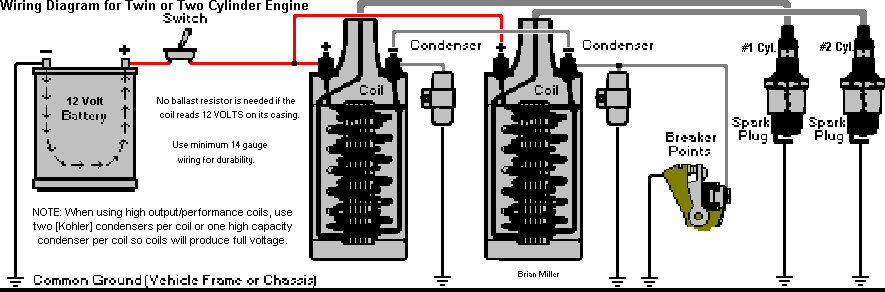
Typical Battery Ignition Points and Condenser/Capacitor Ignition System for a Garden Tractor
If the ignition coil has an internal resistor, connect the wires as shown
below...
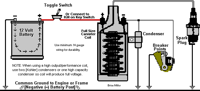
But if the coil require an external resistor
(ballast resistor), connect the wires as shown
below...

[Return to previous paragraph, section or website]
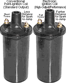 All
conventional point-ignition systems that's installed on most older garden
tractors and automotive engines utilizes a standard-output/stock [20,000
volt] coil. And all automotive (distributor) electronic ignition systems
utilize a (40,000 volt) high-output/performance or OEM automotive electronic
ignition coil. The obvious and visual differences in these coils is by the
height of the center tower. The standard-output/stock coil has a shorter
center tower. In most cases, it's not capable of producing enough volts to
short out (jump) to the small terminals. And all high-output/performance
coils have a taller tower, to keep the spark from shorting or jumping to
the small terminals. Most standard-output/stock battery-powered canister
ignition coils that's designed for a small engine, such as Kohler, Tecumseh,
etc., have a 3.0, 4.0 or 5.0 ohm internal primary resistor. And most
standard-output/stock coils that's designed for a ignition
points/distributor-type ignition system (automotive, farm tractor, etc.)
have a 1.5 ohm internal primary resistor. And most high-output/performance
coils for electronic/distributor-type ignition systems or Distributorless
Ignition System (DIS) have a 0.4 ohm internal primary resistor. The size
of the resistor allow for full coil saturation
so the ignition points will last longer and so the engine will rev up at
open speed (wide open throttle), and if it's for crank-trigger or
flywheel-triggered electronic ignition, to prevent from burning up the control
module.
All
conventional point-ignition systems that's installed on most older garden
tractors and automotive engines utilizes a standard-output/stock [20,000
volt] coil. And all automotive (distributor) electronic ignition systems
utilize a (40,000 volt) high-output/performance or OEM automotive electronic
ignition coil. The obvious and visual differences in these coils is by the
height of the center tower. The standard-output/stock coil has a shorter
center tower. In most cases, it's not capable of producing enough volts to
short out (jump) to the small terminals. And all high-output/performance
coils have a taller tower, to keep the spark from shorting or jumping to
the small terminals. Most standard-output/stock battery-powered canister
ignition coils that's designed for a small engine, such as Kohler, Tecumseh,
etc., have a 3.0, 4.0 or 5.0 ohm internal primary resistor. And most
standard-output/stock coils that's designed for a ignition
points/distributor-type ignition system (automotive, farm tractor, etc.)
have a 1.5 ohm internal primary resistor. And most high-output/performance
coils for electronic/distributor-type ignition systems or Distributorless
Ignition System (DIS) have a 0.4 ohm internal primary resistor. The size
of the resistor allow for full coil saturation
so the ignition points will last longer and so the engine will rev up at
open speed (wide open throttle), and if it's for crank-trigger or
flywheel-triggered electronic ignition, to prevent from burning up the control
module.
Virtually all canister coils appear the same
on the outside. The only sure way to tell what the ohm resistance for virtually
any ignition coil is with a multimeter switched to the ohm
(d) setting. But some coils are marked with
printing on the casing to indicate their ohm resistance, and sometimes the
wording may not be accurate, or it may read: "Use With External Resistor".
But it does not say the size ohm resistance of the
external/ballast resistor that should be used.
So when replacing a coil or when purchasing a new coil for any particular
engine or ignition system, ALWAYS test the value of the ohm resistance to
be 100% certain that the coil will be suitable for the ignition system it
is designed for. Being virtually all ignition coils (and ballast
resistors) appear alike and there's no indication on them of their ohm
resistance, before purchasing a new coil (or ballast resistor), take a digital
multimeter in the small engine shop, auto parts store, farm &
home store, etc. with you and test the item for its ohm resistance
just to make sure you get what you pay for.
Click/tap here to learn how to test
the ohm resistance in a coil.
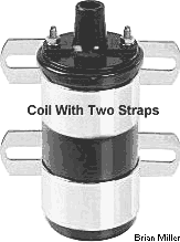 If you've ever experienced the
metal strap on a 12 volt canister ignition coil of breaking due to normal
engine vibration (especially at open RPM
(wide
open throttle) and because the metal itself is too thin, then what you
need to do is either fabricate a strap made of thicker metal, or install
two coil straps as shown in the photo to the right ->, and be sure to
fasten the straps securely. This will double the life of the clamps and lessen
the chances of either strap of ever breaking again.
If you've ever experienced the
metal strap on a 12 volt canister ignition coil of breaking due to normal
engine vibration (especially at open RPM
(wide
open throttle) and because the metal itself is too thin, then what you
need to do is either fabricate a strap made of thicker metal, or install
two coil straps as shown in the photo to the right ->, and be sure to
fasten the straps securely. This will double the life of the clamps and lessen
the chances of either strap of ever breaking again.
 Ever had a good run going down
the track and all of a sudden the engine dies, and you found the cause was
the [failed] ignition coil? Well, chances are, it wasn't designed for use
on a competition garden pulling tractor, especially when the engine is ran
at wide
open throttle. Even new oil-filled canister coils have been known to
fail in a very short time on a competition garden pulling tractor. The reason
some coils fail is due to normal single cylinder engine vibration running
at open RPM. The tiny wires (or windings) inside the coil will vibrate and
break over time. Even the insulation on the windings themselves will "rub"
or scrape against the other internal wires, resulting in a short, and eventual
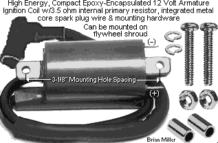
coil failure. That's why it's best to use an epoxy filled or
epoxy-encapsulated coil that can withstand high engine vibration to
prevent the windings from vibrating, shorting out and/or breaking. The epoxy
holds the wires solid, resulting in no vibration of the windings whatsoever.
Most epoxy coils produce up to 45,000 volts, too. So for the little difference
in price, accept no substitutes! Epoxy coils are most reliable for use on
a competition garden pulling tractor. To prevent prematurely burning the
ignition points, it's best to check the coil with a
digital multimeter to determine if it require an external
resistor or not.
Ever had a good run going down
the track and all of a sudden the engine dies, and you found the cause was
the [failed] ignition coil? Well, chances are, it wasn't designed for use
on a competition garden pulling tractor, especially when the engine is ran
at wide
open throttle. Even new oil-filled canister coils have been known to
fail in a very short time on a competition garden pulling tractor. The reason
some coils fail is due to normal single cylinder engine vibration running
at open RPM. The tiny wires (or windings) inside the coil will vibrate and
break over time. Even the insulation on the windings themselves will "rub"
or scrape against the other internal wires, resulting in a short, and eventual
coil failure. That's why it's best to use an epoxy filled or
epoxy-encapsulated coil that can withstand high engine vibration to
prevent the windings from vibrating, shorting out and/or breaking. The epoxy
holds the wires solid, resulting in no vibration of the windings whatsoever.
Most epoxy coils produce up to 45,000 volts, too. So for the little difference
in price, accept no substitutes! Epoxy coils are most reliable for use on
a competition garden pulling tractor. To prevent prematurely burning the
ignition points, it's best to check the coil with a
digital multimeter to determine if it require an external
resistor or not.
A coil with a 1.0 ohm internal primary resistor works great in a 6 volt ignition system to prevent premature burning of the ignition points contacts. A coil with a 1.5 ohm internal primary resistor connected to a 1.4 ohm ballast resistor or resistor wire works great with a distributor/point ignition system to prevent premature burning of the ignition points contacts. And a coil with a 3.0+ ohm internal primary resistor works great for a small engine with ignition points & condenser to prevent premature burning of the ignition points contacts. And coil with a 0.4 ohm internal primary resistor works great with self-energizing solid state electronic, or crank-trigger or flywheel-triggered electronic ignition systems, that's mentioned further down in this website.
Virtually any ignition coil with a 1.0 ohm internal resistor or a GM DIS (Distributorless Ignition System) coil can be safely used in a 6 volt ignition system without a ballast resistor or ignition resistor wire. But to use a 6 volt coil in a 12 volt ignition system, simply use a minimum 1.2 ohm ballast resistor in series between the electrical/power supply and positive (+) coil terminal to reduce the voltage to the coil and current through the ignition points. The coil should produce a strong spark, operate cool to the touch and last longer. The ignition points should last a long time, too. To check if a coil is rather for 6 volts (and can be used in a 12 volt ignition system with a ballast resistor) or for 12 volts, perform the test below Ê.
A battery-powered ignition coil with a primary resistance of 0.6 ohm is most definitely a high-output/performance coil with an output of about 30,000-45,000 volts and the primaries must be switched electronically as that coil will draw around 20 amps. Coils that are around 2.5 to 3.0 ohm are internally ballasted and don't need an external ballast resistor, and have medium voltage output of about 15-35,000 volts. Coils between 4 and 6 ohm are also internally ballasted and do not require a ballast resistor, and have low voltage output of about 12,000-20,000 volts.
Primary resistance is a function of impedance and the lower it is, the faster the rise and fall time of the primary magnetic field and the greater its strength, causing a much higher induced voltage at the secondary winding. ignition points can only handle about 3 amps continuously and thereby put a limit on the coil's output by restricting the primary resistance to 4 or 5 ohm. A ballast resistor is a way of allowing the use of a much lower impedance coil (1.5 ohm) without letting the primary current get too high and burning the ignition points contacts. This almost doubles the coil's output, which, in turn allow for wider plug gaps, so that it can ignite much richer fuel mixtures with the more energetic spark.
Ballast and ignition resistors with a higher ohm value are known as "Point Savers." The higher the ohm primary resistance an ignition resistor has, being if it's a ballast resistor and/or a resistor inside an ignition coil, the longer the ignition points contacts will last (as long as the ignition points/contacts are installed clean, and doesn't become contaminated with dust, oil or water). A 12 volt ignition coil with a 3.0 ohm internal primary resistor connected to a 1.6 ohm ballast resistor (highest value ballast resistor available) when used in a ignition points ignition system will allow the ignition points contacts to possibly last the life of the engine. And just one medium capacity [Kohler] condenser/capacitor can be used. Install the 1.6 ohm ballast resistor between the coil positive (+) terminal and wire coming from the ignition switch to the coil. This will allow the ignition points to possibly last the life of the engine. Because the increased resistance allow a very low current (flow of electricity) pass through the ignition points contacts, resulting in much less electrical arcing of the contacts. This will drastically reduce the premature burning away of the platinum coating on the ignition points contacts. Also, a suppression/carbon core spark plug wire and resistor type spark plug shouldn't be used in this system due to overheating of the ignition coil. Therefore, it's best that a metal core spark plug wire and copper core/non-resistor spark plug be used. The ignition system will still provide a strong spark because an average small engine requires only a fraction of voltage from the coil. And this is best used with general lawn & garden, snow removal, etc. equipment engines, and not for competition pulling.
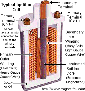 All 12 volt automotive
high-output/performance or OEM electronic ignition coils have more secondary
wire windings than in a standard-output/stock coil. This is how they produce
more voltage to create a stronger spark. When used with a ignition points
and condenser/capacitor ignition system, the energy of the primary windings
within the coil is transferred in the condenser/capacitor. And in most cases,
All 12 volt automotive
high-output/performance or OEM electronic ignition coils have more secondary
wire windings than in a standard-output/stock coil. This is how they produce
more voltage to create a stronger spark. When used with a ignition points
and condenser/capacitor ignition system, the energy of the primary windings
within the coil is transferred in the condenser/capacitor. And in most cases,
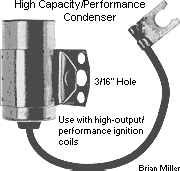
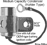 one medium capacity condenser/capacitor isn't capable of handling
the excessive amount of electricity from the primary windings at open energize
the secondary windings within the coil, thus allowing the coil to produce
a low voltage or weak spark at any RPM, which will cause the engine to idle
poorly and run poorly. Sometimes when using a (40,000 volt)
high-output/performance or OEM automotive electronic ignition coil with one
medium capacity (Kohler) condenser/capacitor, black smoke will blow out the
exhaust at idle and flames will shoot out the exhaust at open RPM
(wide
open throttle).
one medium capacity condenser/capacitor isn't capable of handling
the excessive amount of electricity from the primary windings at open energize
the secondary windings within the coil, thus allowing the coil to produce
a low voltage or weak spark at any RPM, which will cause the engine to idle
poorly and run poorly. Sometimes when using a (40,000 volt)
high-output/performance or OEM automotive electronic ignition coil with one
medium capacity (Kohler) condenser/capacitor, black smoke will blow out the
exhaust at idle and flames will shoot out the exhaust at open RPM
(wide
open throttle).
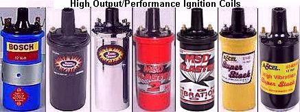 For a high-output/performance
ignition system operate at 100% efficiency and produce more voltage at any
RPM, it's best to use two medium capacity ignition condensers/capacitors
or one high capacity/performance condenser/capacitor. Using either two standard
capacity (Kohler) condensers/capacitors or one high capacity/performance
condenser/capacitor will help the engine to idle better, run smoother, and
produce more horsepower at open RPM. When using 2 condensers, connect the
wire of each condenser to the negative terminal on the coil and ground the
bodies of the condensers. If an engine is built right, the ignition timing
is set correct, and if the carburetor is adjusted correctly, with two medium
capacity (Kohler) condensers/capacitors or one high capacity/performance
condenser/capacitor, the exhaust (appearance) should be cleaner at idle,
and with no flames at open RPM. A stock or standard-output/stock coil will
not produce more voltage than what it is designed for with two medium capacity
(Kohler) condensers/capacitors or one high capacity/performance
condenser/capacitor. But it will produce 100% voltage with two medium capacity
(Kohler) condensers/capacitors or one high capacity/performance
condenser/capacitor. And with A-1 Miller's
flywheel- or
crank-trigger electronic ignition, if
an electronic ignition control module/unit (ICU) with a high capacity transistor
is used, a standard-output/stock or high-output/performance coil will produce
100% voltage regardless. And if you're wondering, any type of ignition points
can be used with virtually any type of coil and condenser/capacitor.
For a high-output/performance
ignition system operate at 100% efficiency and produce more voltage at any
RPM, it's best to use two medium capacity ignition condensers/capacitors
or one high capacity/performance condenser/capacitor. Using either two standard
capacity (Kohler) condensers/capacitors or one high capacity/performance
condenser/capacitor will help the engine to idle better, run smoother, and
produce more horsepower at open RPM. When using 2 condensers, connect the
wire of each condenser to the negative terminal on the coil and ground the
bodies of the condensers. If an engine is built right, the ignition timing
is set correct, and if the carburetor is adjusted correctly, with two medium
capacity (Kohler) condensers/capacitors or one high capacity/performance
condenser/capacitor, the exhaust (appearance) should be cleaner at idle,
and with no flames at open RPM. A stock or standard-output/stock coil will
not produce more voltage than what it is designed for with two medium capacity
(Kohler) condensers/capacitors or one high capacity/performance
condenser/capacitor. But it will produce 100% voltage with two medium capacity
(Kohler) condensers/capacitors or one high capacity/performance
condenser/capacitor. And with A-1 Miller's
flywheel- or
crank-trigger electronic ignition, if
an electronic ignition control module/unit (ICU) with a high capacity transistor
is used, a standard-output/stock or high-output/performance coil will produce
100% voltage regardless. And if you're wondering, any type of ignition points
can be used with virtually any type of coil and condenser/capacitor.
NOTE: The condenser body must be securely fastened to the engine/chassis ground for the engine to run smooth. If the condenser is loose in its bracket, the bracket can be squeezed slightly with large pliers to be made oblong or egg-shape, and then the condenser will remain tight inside it. But if an engine idles well, but runs erratically above idle, like it hits and misses, pops and backfires, then chances are, it needs a new condenser/capacitor. And always install a condenser with the wire or terminal facing downward so rain water and/or when washing off engine, water will not enter inside condenser, ruining it. With water inside the condenser, this will cause the engine to run erratically when revved up. Or better yet, upgrade/convert the engine with an A-1 Miller's maintenance-free and weather-proof battery-powered flywheel-triggered electronic ignition system for a stronger and more stable spark, quicker starts, smoother idle and overall better running engine.
When choosing a (40,000 volt) high-output/performance or OEM automotive electronic ignition coil, such as a Chrysler electronic ignition canister coil, if it reads on the casing: "use with electronic ignition" (or something like this), all this means is if the coil is used with full 12 volts, and with ignition points and [one standard capacity] condenser/capacitor, the ignition points contacts will not last long and burn up prematurely due to the higher voltage going through them. To use the coil, simply install a [1.6 ohm resistance] ballast resistor before the coil to decrease the voltage going through the coil and the ignition points, and the ignition points should last longer. And definitely use two medium capacity ignition condensers/capacitors or one high capacity/performance condenser/capacitor so the coil will produce more voltage. (When using 2 condensers, connect the wire of each condenser to the negative terminal on the coil and ground the bodies of the condensers.) NOTE: The condenser body must be securely fastened to the engine/chassis ground for the engine to run smooth. If the condenser is loose in its bracket, the bracket can be squeezed slightly with large pliers to be made oblong or egg-shape, and then the condenser will remain tight inside it. But if an engine idles well, but runs erratically above idle, like it hits and misses, pops and backfires, then chances are, it needs a new condenser/capacitor. And always install a condenser with the wire or terminal facing downward so rain water and/or when washing off engine, water will not enter inside condenser, ruining it. With water inside the condenser, this will cause the engine to run erratically when revved up. Or better yet, upgrade/convert the engine with an A-1 Miller's maintenance-free and weather-proof battery-powered flywheel-triggered electronic ignition system for a stronger and more stable spark, quicker starts, smoother idle and overall better running engine.
Causes of Engine "Popping" or Backfire -
Causes of Most Ignition Coil Failures - Most battery-powered ignition coils will last the life of an engine. However, if a quality coil keeps going bad for no apparent reason, here are the reasons that can cause this...
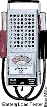
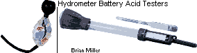 If a garden tractor or small engine equipment is equipped with
an automotive battery, it may have a dead cell or all the cells may
be weak (defective battery.) Unlike in an automobile, and if the starter
motor is in good condition, a weak automotive battery will have more than
enough cranking amps to crank over a small, single- or two-cylinder engine
with no problem, and a drop in the battery's cranking amps wouldn't be that
noticeable while cranking the engine to start it. Whether if it's in a garden
tractor , small motorized vehicle or an automobile, an automotive battery
with a dead cell or weak cells will cause the charging system to continually
try to recharge the battery, but instead of the battery taking full charge,
the charging system will put too much voltage through the coil for long periods
of time, causing the primary windings within the coil to burn up. If an engine
has a battery-powered electronic ignition, this too, could burn up the electronic
ignition control module, burn out light bulbs and electrical accessories.
To determine if a battery is defective, use a load tester for sealed-top
batteries, and for batteries with removable caps, test the battery's acid
condition with a hydrometer battery tester (glass tube with floating balls
[pocket size] or a floating bulb [full size]; which are available at virtually
any auto parts store). Therefore, if it's not already equipped, it's best
to install an ammeter/amp gauge to monitor the charging system.
If a garden tractor or small engine equipment is equipped with
an automotive battery, it may have a dead cell or all the cells may
be weak (defective battery.) Unlike in an automobile, and if the starter
motor is in good condition, a weak automotive battery will have more than
enough cranking amps to crank over a small, single- or two-cylinder engine
with no problem, and a drop in the battery's cranking amps wouldn't be that
noticeable while cranking the engine to start it. Whether if it's in a garden
tractor , small motorized vehicle or an automobile, an automotive battery
with a dead cell or weak cells will cause the charging system to continually
try to recharge the battery, but instead of the battery taking full charge,
the charging system will put too much voltage through the coil for long periods
of time, causing the primary windings within the coil to burn up. If an engine
has a battery-powered electronic ignition, this too, could burn up the electronic
ignition control module, burn out light bulbs and electrical accessories.
To determine if a battery is defective, use a load tester for sealed-top
batteries, and for batteries with removable caps, test the battery's acid
condition with a hydrometer battery tester (glass tube with floating balls
[pocket size] or a floating bulb [full size]; which are available at virtually
any auto parts store). Therefore, if it's not already equipped, it's best
to install an ammeter/amp gauge to monitor the charging system.
Why Do Some Magneto Armature Ignition Coils To Go Bad?
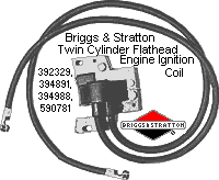
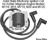 I think the Briggs & Stratton, Kohler KT-series and Magnum
opposed twin cylinder opposed twin cylinder engines are the best that was
made, but their armature ignition coil has its shortcomings. The real problem
with these engines is they use one (small) armature ignition coil to fire
two spark plugs, one per cylinder, and after several years of use, sometimes
the coil will fail to produce a spark, rather if the engine has ignition
points and condenser/capacitor, Magnetron™ or a solid state electronic module.
Unfortunately, some armature ignition coils don't last the life of the engine.
As the spark plug's electrode and/or the resistor in a
resistor
type spark plug deteriorates, the secondary windings within the coil
is forced to produce more voltage to fire the plug at higher RPM. Eventually,
the increase in voltage will overheat and eventually burn up the secondary
windings within the coil, causing coil failure. This is why quality-made
copper core/non-resistor spark plugs should always be used with a small or
magneto armature ignition coil. The coil burns out because one coil must
fire two spark plugs at one time with the plug gaps set at .030" each (factory
recommended setting). With these size gaps, this is the same as firing one
spark plug with a gap of .060"! Most magneto coils are not designed to produce
this much voltage and may not last too long when they do. The coil is forced
to produce more voltage than is necessary to fire both plugs and this causes
the secondary windings within the coil to overheat and eventually burn out.
And as the spark plugs deteriorate with age, the coil is forced to produce
even more voltage to make a spark through the weak plugs. So to lessen the
chance of a good coil going bad (again),
set the spark plug gaps at .015"
each. The .015" gaps will simulate having just one spark plug with a .030"
gap, and the coil will operate much cooler and should last a lot longer.
Dyno tests proved that the engine will still start quicker, idle smoothly
and rev up to full RPM with no hesitation whatsoever as it did with the .030"
spark plug gaps. And be sure to set the armature ignition coil's
laminations-to-flywheel magnet air gap/clearance at .010" or .25mm. The paper
box a new coil comes in can be used as a gauge. It has pretty much the same
thickness as a business card or poster board.
I think the Briggs & Stratton, Kohler KT-series and Magnum
opposed twin cylinder opposed twin cylinder engines are the best that was
made, but their armature ignition coil has its shortcomings. The real problem
with these engines is they use one (small) armature ignition coil to fire
two spark plugs, one per cylinder, and after several years of use, sometimes
the coil will fail to produce a spark, rather if the engine has ignition
points and condenser/capacitor, Magnetron™ or a solid state electronic module.
Unfortunately, some armature ignition coils don't last the life of the engine.
As the spark plug's electrode and/or the resistor in a
resistor
type spark plug deteriorates, the secondary windings within the coil
is forced to produce more voltage to fire the plug at higher RPM. Eventually,
the increase in voltage will overheat and eventually burn up the secondary
windings within the coil, causing coil failure. This is why quality-made
copper core/non-resistor spark plugs should always be used with a small or
magneto armature ignition coil. The coil burns out because one coil must
fire two spark plugs at one time with the plug gaps set at .030" each (factory
recommended setting). With these size gaps, this is the same as firing one
spark plug with a gap of .060"! Most magneto coils are not designed to produce
this much voltage and may not last too long when they do. The coil is forced
to produce more voltage than is necessary to fire both plugs and this causes
the secondary windings within the coil to overheat and eventually burn out.
And as the spark plugs deteriorate with age, the coil is forced to produce
even more voltage to make a spark through the weak plugs. So to lessen the
chance of a good coil going bad (again),
set the spark plug gaps at .015"
each. The .015" gaps will simulate having just one spark plug with a .030"
gap, and the coil will operate much cooler and should last a lot longer.
Dyno tests proved that the engine will still start quicker, idle smoothly
and rev up to full RPM with no hesitation whatsoever as it did with the .030"
spark plug gaps. And be sure to set the armature ignition coil's
laminations-to-flywheel magnet air gap/clearance at .010" or .25mm. The paper
box a new coil comes in can be used as a gauge. It has pretty much the same
thickness as a business card or poster board.
The use of resistor type spark plugs shortens the life of most small engine self-energizing magneto or solid state electronic armature ignition coil/modules. Therefore, for best engine performance and longevity of the coil, it's best to use a high quality copper core/non-resistor spark plug gapped at .025" for single cylinder and V-twin engines, and .015" each for opposed twin cylinder engines to prevent overheating of secondary windings within the coil and possibly causing premature coil failure. Set the armature to the flywheel magnet clearance (air gap) at .010" or .25mm. And the easiest and most accurate way to set the air gap is to use a business card, poster board, or part of the box the new coil came in. These measure about .010" or .25mm thickness. Place a strip of the paper or box between the coil's armature and magnet in the flywheel and allow the magnet to pull the armature to it, then tighten the coil mounting screws securely. Also, when a coil goes bad, save the spark plug wire(s) off the defective coil. These have a stranded metal core wire, and with a coil (distributor) terminal and coil tower boot installed, it/they can be used on an engine with a magneto, battery-powered or A-1 Miller's custom-made flywheel- or crank-trigger electronic ignition system.
Or instead of doing the above È, if an older Briggs & Stratton opposed twin cylinder flathead engine has ignition points, it can be easily converted to the more reliable and higher output battery ignition (for a stronger spark). The B&S ignition points can be still used, but two 12 volt automotive canister ignition coils or one battery-powered ignition coil with dual plug terminals (as described above È) with spark plug wires, and two battery ignition condensers/capacitors will need to be used. The spark plug gaps can be set at .035", and the ignition timing can be set by the width of the ignition points gap (.020") or with a strobe timing light after the flywheel is degreed in with timing marks. The timing light connects to the battery and spark plug wire.
How to Convert a Briggs & Stratton Engine to Battery-Powered Flywheel-Triggered Ignition -
 For virtually any B&S engine
with a magnet embedded on the circumference of the flywheel, a hall effect
(detects a magnet) proximity sensor can be used in place of the OEM armature
ignition coil to trigger the ignition. Being a non-magnetic pickup coil will
generate electricity as it passes the full width of the North and South poles
of the magnet, it will produce a double spark, which may effect how the engine
runs. The hall effect proximity sensor on the other hand will work better
because it's activated just off the South pole of the magnet, producing a
single spark. And a sturdy bracket will need to be fabricated to mount the
sensor. The sensor will fire both cylinders at the same time (wasted spark).
A Chrysler or Ford ignition control module will need to be used with a single
ignition coil with dual wires. The timing will need to be set just as the
sensor come within the leading edge of the South pole of the magnet, so the
engine will produce full power.
For virtually any B&S engine
with a magnet embedded on the circumference of the flywheel, a hall effect
(detects a magnet) proximity sensor can be used in place of the OEM armature
ignition coil to trigger the ignition. Being a non-magnetic pickup coil will
generate electricity as it passes the full width of the North and South poles
of the magnet, it will produce a double spark, which may effect how the engine
runs. The hall effect proximity sensor on the other hand will work better
because it's activated just off the South pole of the magnet, producing a
single spark. And a sturdy bracket will need to be fabricated to mount the
sensor. The sensor will fire both cylinders at the same time (wasted spark).
A Chrysler or Ford ignition control module will need to be used with a single
ignition coil with dual wires. The timing will need to be set just as the
sensor come within the leading edge of the South pole of the magnet, so the
engine will produce full power.
And if you're wondering if surface rust on flywheel magnets reduces magnetism and/or strength of the spark on the armature of a magneto armature ignition coil, well, I know for a proven fact that surface rust does not affect magnetism or strength of the spark whatsoever. This is the same as saying that pure, undiluted automotive antifreeze coolant will freeze solid in sub-zero freezing weather. It will NOT freeze! And despite of what you've probably heard, putting sugar in the gas tank will NOT ruin the engine! Read about it here: snopes.com: Sugar in the Gas Tank. Don't just theorize about such things, believe in myths, rumors or what some [delusional] people/mechanics/technicians tell you. Perform a scientific test to prove to yourself and debunk the myths. I always do.
And for anyone who's wondering, an standard-output/stock automotive battery ignition condenser/capacitor with an automotive canister ignition coil will work on virtually any one- or two-cylinder air-cooled engine that use the battery ignition system. But when using two 12 volt automotive ignition coils on a twin- or two-cylinder engine with conventional ignition points, be sure to use two condensers/capacitors as well, one for each coil, only if the coil(s) requires one. Otherwise, the engine will idle, but may not rev up. And there's a very little difference between the Kohler battery ignition condenser/capacitor and an automotive [GM, Ford or Chrysler] ignition [ignition points] condenser/capacitor. So either can be used on a small engine.
Replacing an Obsolete, Hard to Find or High Dollar Magneto or Solid State Armature Ignition Coil with Another Type of Coil - | [Top of Page]
Kohler, Tecumseh, Briggs & Stratton and other makes (manufacturers) of small engines don't manufacture the ignition coils they install on their engines. Instead, they purchase them from a reputable coil manufacturer, and although the mounting part of armatures are different, some coils will interchange. So whenever a points and condenser type of magneto coil or a solid state electronic ignition coil goes bad and is no longer available new, hard to find or is cost-prohibitive, then perhaps a new coil that's made for a different make and model of small engine could be used on the engine with the faulty coil, by removing the new coil from its armature, and installing it on the original coil's armature. But this will only work if the center hole in the replacement coil is the same size or slightly larger than the original coil's armature, and if the spark plug wire is of the appropriate length. If the replacement coil's center hole is slightly larger, several thin strips of sheet metal can be wedged inside the coil for a stronger magnetic field to create a strong spark. Personally, I've noticed that nowadays, most [aftermarket] small engine coils appear the same, but they're mounted on different types of armatures for various makes and models of small engines. This is because they all work exactly the same off the magnet in or on the flywheel to create a strong spark. This is because it cost less for most manufacturers to produce the same type of coil, and install it in different armatures.
With your faulty coil/armature in hand, visit your local lawn mower repair shops or small engine businesses and ask them if they have another new coil in stock that closely match yours. Then compare the armature and length of the spark plug wire of the replacement coil to your original coil and armature. Maybe you'll get lucky and you can transfer the replacement coil onto your original armature. I've done this several times for my customers and it works great!
Spark Plug Wires and Spark Plug Boots -
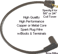
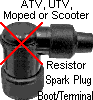 Virtually all copper or metal core spark plug wires rarely
lose resistance, resulting in a weak spark. The only time they need replacing
is when damaged beyond use. A spark plug wire can be tested with an analog
multimeter switched to the X1K ohm (d) setting
or for a digital multimeter, switched to the 2000K ohm
(d) setting. Also, virtually all small engine
lawn & garden equipment spark plug wires have a stranded metal core wire
and are considered high-performance because they have zero ohm resistance.
Most ATV's, UTV's, mopeds and scooters have a spark plug boot with a resistor
built-in the terminal. The resistor reduce the amount of voltage going to
the spark plug, which will cause the secondary windings within the ignition
coil to overheat and could eventually cause the coil to go bad or fail to
produce a spark.
Virtually all copper or metal core spark plug wires rarely
lose resistance, resulting in a weak spark. The only time they need replacing
is when damaged beyond use. A spark plug wire can be tested with an analog
multimeter switched to the X1K ohm (d) setting
or for a digital multimeter, switched to the 2000K ohm
(d) setting. Also, virtually all small engine
lawn & garden equipment spark plug wires have a stranded metal core wire
and are considered high-performance because they have zero ohm resistance.
Most ATV's, UTV's, mopeds and scooters have a spark plug boot with a resistor
built-in the terminal. The resistor reduce the amount of voltage going to
the spark plug, which will cause the secondary windings within the ignition
coil to overheat and could eventually cause the coil to go bad or fail to
produce a spark.
Any spark plug wire, rather if it's a real-known brand name or aftermarket, should always be tested for it's ohm resistance. The best way to determine if a spark plug wire has a carbon- or metal core wire (without stripping the insulation away) is with a set on the 2000K ohm (d) setting for a digital multimeter or x1K setting for an analog multimeter. Touch the multimeter leads together to adjust for (analog) or take note of (digital) the zero resistance. Now connect the leads of the multimeter to the ends of the spark plug wire. If the reading displays zero resistance, it's a metal core plug wire. But if it displays any resistance at all, it's most likely a suppression/carbon core spark plug wire. Certain [plastic] spark plug caps (boot/terminal) have a built-in resistor, which will deliver about half the voltage to the spark plug, resulting in poor engine performance, especially at high RPM. So for better engine performance, try to avoid using a resistor spark plug cap (boot/terminal). Click/tap here to learn how to test the ohm resistance of a spark plug wire or spark plug boot/terminal.
copper core/non-resistor spark plugs, such as the Autolite 216 and Champion 844 (H10C), and small engine spark plug wires, which have a metal (copper or steel) wire, are the best things to use for competition pulling. By using a copper core/non-resistor plug and metal core wire, more voltage will reach the spark plug's tip, especially under high compression when the engine is running at wide open throttle, resulting in a much stronger spark. A stock, standard-output/stock ignition coil with a metal spark plug wire and a copper core/non-resistor spark plug will produce about the same voltage at the spark plug's tip as a high-output/performance coil with a suppression/carbon core spark plug wire and a resistor type spark plug.
On virtually any ignition system, the coil produce is less voltage at idle or cruising speeds (in an automobile) when the throttle plate is partially open, and when the throttle plate is opened more or in the wide open throttle position to increase the engine's RPM, being the combustion chamber is more air (and fuel) to build up more compression, the coil is forced to produce more voltage to fire the spark(s). As a suppression/carbon core spark plug wire and/or resistor type spark plug gets weak (they deteriorate with use), the ignition coil is forced to produce even more voltage. Eventually, as the suppression/carbon core wire and/or resistor plug gets so weak, the coil can't produce enough voltage and an engine misfire occurs, or the engine will die out when revved up. This will happen even with a high-output/performance coil. It just takes longer for the high-output coil to reach maximum voltage as the suppression/carbon core spark plug wire and/or resistor type spark plug deteriorate to cause an engine misfire. The use of aged and deteriorated suppression/carbon core spark plug wire and/or an old resistor type spark plug will also cause a good coil to eventually fail because the secondary windings within the coil overheat and eventually burn up from producing excessive voltage to fire the plug.
If a spark plug wire has no markings rather if it's a suppression/carbon
or metal core wire type, it can be tested with an
analog or
digital multimeter switched to the ohm
(d) setting. Connect the leads of the meter
to the terminals of the spark plug wire, if it reads full scale, it's a metal
core type. But if the meter reads about halfway, it's suppression/carbon
core spark plug wire. The same test can be performed on a questionable spark
plug, with accurate results. And remember - spark plug wires and spark plugs
are like women, it's what's on the inside that matters.

If a coil did not come with the spark plug terminal and boot installed, to install terminal on spark plug wire, strip off a short part of the insulation and bend over the wire to make full connect with the terminal, and use a spark plug wire crimping tool to secure the terminal on the spark plug wire, then apply automotive grease on the spark plug wire and inside boot so it will slide easily on the wire and over the terminal.
A spark plug gap of .035" works best with gas, and a .060" gap works better with methanol because it's a "richer" fuel. When burning methanol, the wider gap works best with a (40,000 volt) high-output/performance or OEM automotive electronic ignition coil, metal core spark plug wire and non-resistor type spark plug.
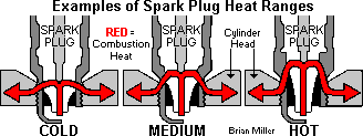 And the use of a "cold", "medium",
or "hot" heat range spark plug makes absolutely no difference in a competition
Kohler pulling engine with a steel flywheel and billet cylinder head that
have no fins because these engines have no cooling system or air blowing
past the cylinder and across the head to dissipate the heat from the combustion
chamber/spark plug. When there's no cooling fins on the flywheel or with
an electric fan not running to cool the engine, nothing will maintain the
temperature of the engine, except for a swift breeze on a windy day (only
on a tractor with no side shields).
And the use of a "cold", "medium",
or "hot" heat range spark plug makes absolutely no difference in a competition
Kohler pulling engine with a steel flywheel and billet cylinder head that
have no fins because these engines have no cooling system or air blowing
past the cylinder and across the head to dissipate the heat from the combustion
chamber/spark plug. When there's no cooling fins on the flywheel or with
an electric fan not running to cool the engine, nothing will maintain the
temperature of the engine, except for a swift breeze on a windy day (only
on a tractor with no side shields).
Did you know that installing two spark plugs per cylinder doesn't help to increase the horsepower output of an engine whatsoever? Simply because one plug will be running hot (exhaust side) and the other will be cool (intake side). Engine horsepower is generated from the heat source, because heat is how an engine produce power. When the spark plug in the cylinder head is located over the exhaust valve, this maintains the majority of the heat in the combustion chamber in one area. When heat is maintained in one particular area in any given combustion chamber, the increase in horsepower will be much greater, especially at high RPM. Burning fuel within a combustion chamber will "find" or locate the main heat source. The fuel will burn more thoroughly, allowing the engine to produce more horsepower at any RPM. If the plug is located in the center of the combustion chamber, the incoming fuel could splash against the plug's tip and cause the engine to misfire or run erratic at high speed, especially when burning methanol fuel. And the plug could easily become fouled when burning gas, especially when the engine is cold. So it's best to install just one spark plug positioned over the exhaust valve with the plug gap set at .060". Because a .060" gap will simulate having two spark plugs. Use of a (40,000 volt) high-output/performance or OEM automotive electronic ignition coil will help produce a stronger spark, too.
Index the Spark Plug(s) to Help Increase Engine Horsepower and Torque -
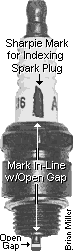

 An indexing washer
is a special washer of a specific thickness. Indexing washer(s) is/are placed
on the threads of the spark plug(s) to position it with the open/exposed
gap facing the center of the piston when the plug is properly torqued in
the head. When the open or exposed gap face the piston, this helps in a complete
burning of the fuel, resulting in a more thorough combustion, so the engine
will produce up to 10% more horsepower and torque when using a tractor under
extreme conditions, such as heavy mowing, garden plowing, pushing/blowing
snow or competition pulling. Indexing washers come in various thicknesses,
and one of a certain thickness is used to
index the spark plug(s). The thin shims/washers for Kohler
balance gears can also be used as indexing washers for spark plug(s). To
know exactly where the open gap is when the spark plug is installed in the
head, place a mark (line) with a permanent ink marker
(Sharpie,
Magic Marker,
Marks-A-Lot, etc.) on the porcelain in-line with the open
gap at the tip of the spark plug as shown in the photo to the right ->.
Also, leave the original compression washer on the flat seat spark plug(s)
and add the indexing washer(s) as required, tighten spark plug with ink mark
on porcelain/open gap facing near center of the piston.
An indexing washer
is a special washer of a specific thickness. Indexing washer(s) is/are placed
on the threads of the spark plug(s) to position it with the open/exposed
gap facing the center of the piston when the plug is properly torqued in
the head. When the open or exposed gap face the piston, this helps in a complete
burning of the fuel, resulting in a more thorough combustion, so the engine
will produce up to 10% more horsepower and torque when using a tractor under
extreme conditions, such as heavy mowing, garden plowing, pushing/blowing
snow or competition pulling. Indexing washers come in various thicknesses,
and one of a certain thickness is used to
index the spark plug(s). The thin shims/washers for Kohler
balance gears can also be used as indexing washers for spark plug(s). To
know exactly where the open gap is when the spark plug is installed in the
head, place a mark (line) with a permanent ink marker
(Sharpie,
Magic Marker,
Marks-A-Lot, etc.) on the porcelain in-line with the open
gap at the tip of the spark plug as shown in the photo to the right ->.
Also, leave the original compression washer on the flat seat spark plug(s)
and add the indexing washer(s) as required, tighten spark plug with ink mark
on porcelain/open gap facing near center of the piston.
Furthermore, when the spark plug in the cylinder head is located over the exhaust valve, this maintains the majority of the heat in the combustion chamber in one area, instead of being spread throughout the combustion chamber. Because when [good] heat is maintained in one particular area in any given combustion chamber, the increase in horsepower will be much greater, especially at high RPM. Burning fuel within a combustion chamber will seek out or "find" the main heat source. The fuel will burn more thoroughly, helping the engine to produce more horsepower at any RPM. On a flathead engine, when the plug is located in the center of the combustion chamber, or more or less between the valves, when burning methanol fuel, the incoming fuel could splash against the plug's tip and cause the engine to misfire or run erratic at high speed. Also, sometimes the plug could easily become fouled when burning gas, especially when the engine is being choked or primed with fuel to start it when it's cold. [Return to previous paragraph, section or website]
Advertisement: (Prices are subject to change without notice.)
| Click here to contact A-1 Miller's Performance Enterprises to place an order, send your parts for repairing, and/or for FREE professional and honest technical customer service assistance and support and payment options. Please contact A-1 Miller's if you need part(s) and/or service(s)(s) performed that's not listed or mentioned in this website. |
| Indexing
Washers for Flat Seat Spark Plugs with 14mm Threads. Positions spark
plug with the open/exposed gap facing the center of the piston in combustion
chamber of flathead engines for up to 10% more horsepower and torque when
using tractor under extreme conditions, such as heavy mowing, garden plowing,
pushing/blowing snow or competition pulling. To know exactly where the open
gap is when the spark plug is installed in the head, place a mark (line)
with a permanent ink marker
(Sharpie,
Magic Marker,
Marks-A-Lot, etc.) on the porcelain in-line with the open
gap at the tip of the spark plug as shown in the photo to the right ->.
Also, leave the original compression washer on the spark plug and add the
indexing washer(s) as required, tighten spark plug with ink mark on
porcelain/open gap facing near center of the piston. Made of hardened steel.
Available in the following thicknesses: .005", .010" and .015".
.75¢ each, plus shipping & handling.
|
How to Test the Value of the ohm
() Resistance of an Ignition Coil, Ballast Resistor,
Ignition Resistor Wire, Spark Plug Wire or Spark Plug Boot/Terminal -
[Return to previous paragraph, section
or website]
Virtually all ceramic-body ballast resistors
do not have any indication or markings of its
ohm resistance.
Therefore, it will need to be tested to verify the resistance for it to work
correctly with the connected electrical device. If it's used resistor, inspect
the ceramic portion for signs of overheating. An overheated (overloaded)
resistor will be dark or blackened. Such a resistor should not be used. And
most 12 volt ignition coils have either an 1.5 or 3.0 ohm internal primary
resistor. 6 volt coils have a 1.0 ohm internal primary resistor. All
battery-powered ignition coils have an internal resistor and some coils require
an additional external resistor for two reasons: 1: to provide a stronger
spark so a cold engine will start quicker (as the engine warms up, the resistor
gradually drops the voltage to around 9 volts to the ignition points contacts
so they will last longer, or to the electronic ignition control unit to keep
it from burning up); and 2: to protect the primary windings from current
spikes from the charging generator or alternator. Also, certain [plastic]
spark plug caps (boot/terminal)
have a built-in resistor, which will deliver about half the voltage to the
spark plug, resulting in poor engine performance, especially at high RPM.
So for better engine performance, try to avoid using a
resistor spark plug cap (boot/terminal). Anyway, the best
way to determine the value of the resistor is with a digital multimeter.
When in doubt of the ohm value in a coil, etc., it can be tested as follows:
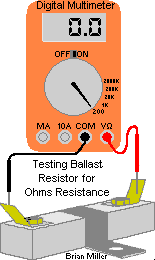
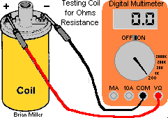 Spark plug wires can be accurately and easily tested with either
an
analog or
digital multimeter, but the accuracy of testing the internal
resistor in a coil, ballast resistor or ignition resistor wire is more
complicated when performed with an analog multimeter. Therefore, the easiest
and most accurate way to test for the ohm resistance of the before mentioned
is with a digital multimeter (DMM, DVOM). IMPORTANT - For an accurate
reading, make sure the battery in the digital multimeter is fully charged,
and the digital multimeter and the part to be tested are warmed to room
temperature (72°F).
mA] receptacle and plug the black test lead connector
in the COM receptacle. For the most accurate reading, select the 200 ohm
() setting. On most digital multimeters, resistance
is denoted by the capital Greek letter Omega (),
which stand for ohm. (Named after
Georg Ohm.)
) setting of a digital multimeter.
It may take a few seconds for the multimeter to absorb the full resistance
in the resistor until it displays the lowest resistance. Make a note of this
reading.
Spark plug wires can be accurately and easily tested with either
an
analog or
digital multimeter, but the accuracy of testing the internal
resistor in a coil, ballast resistor or ignition resistor wire is more
complicated when performed with an analog multimeter. Therefore, the easiest
and most accurate way to test for the ohm resistance of the before mentioned
is with a digital multimeter (DMM, DVOM). IMPORTANT - For an accurate
reading, make sure the battery in the digital multimeter is fully charged,
and the digital multimeter and the part to be tested are warmed to room
temperature (72°F).
mA] receptacle and plug the black test lead connector
in the COM receptacle. For the most accurate reading, select the 200 ohm
() setting. On most digital multimeters, resistance
is denoted by the capital Greek letter Omega (),
which stand for ohm. (Named after
Georg Ohm.)
) setting of a digital multimeter.
It may take a few seconds for the multimeter to absorb the full resistance
in the resistor until it displays the lowest resistance. Make a note of this
reading.
Being virtually all ignition coils and ballast resistors appear alike and there's no indication on them of their ohm resistance, before purchasing a new coil or ballast resistor, take a digital multimeter in the small engine shop, auto parts store, farm & home store, etc. with you and test the item for its ohm resistance to make sure you get what you pay for. [Return to previous paragraph, section or website]
Advertisement: (Prices are subject to change without notice.)
| Click here to contact A-1 Miller's Performance Enterprises to place an order, send your parts for repairing, and/or for FREE professional and honest technical customer service assistance and support and payment options. Please contact A-1 Miller's if you need part(s) and/or service(s)(s) performed that's not listed or mentioned in this website. | |
| FYI - I can install my custom-made flywheel- or crank-triggered electronic ignition system on virtually any older small engine and/or rewire your lawn & garden tractor, garden tractor, small engine equipment, small motorized vehicle or competition garden pulling tractor so all the electrical accessories will work correctly and the engine will start quicker, idle smoothly and rev up to full RPM with no hesitation whatsoever. I have the knowledge, skills, all the parts and tools to perform a professional job. I've rewired many customer's lawn & garden tractors, garden tractors, small engine equipment and competition garden pulling tractors through the years with great results. If you're interested, please click/tap here for contact information and directions to A-1 Miller's shop. | |
| NOTE: All parts listed in this website are NEW, unless otherwise stated. I do not sell cheap junk! As a matter of fact, most OEM Kohler parts are made in China now. Kohler owns some of the factories in China that make the parts. And most aftermarket parts are also made by Kohler in China. Kohler just place the part(s) in a generic box and sell them for less money. So when purchasing a genuine OEM Kohler part that come in a box with the Kohler name on it, you're really just paying more money for the name. And as far as some parts being no longer available - either the parts didn't sell well or the EPA is trying to phase out parts for the old cast iron block flathead engines because they produce more air pollution than the newer OHV engines. | |
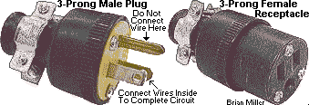  SAFETY FIRST!
Break-Away / Grounding-Type Safety Kill Switch with
Pull-Pin. Use for competition pulling only;
mount on rear of tractor above hitch. When the pin is pulled, this switch
grounds the ignition coil from producing spark. Wiring Instructions - If
using with a self-energizing magneto or solid state electronic ignition systems:
Connect one wire to the tractor chassis/frame, and connect the other wire
to the points/condenser wire that connects to the coil negative (–)
terminal, or to the kill terminal on the solid state electronic ignition
coil/module. If using with a battery-powered ignition system: Connect one
wire to the tractor chassis/frame, and connect the other wire to the coil
negative (–) terminal. NOTE: With battery-powered ignition, as soon
as the pin is pulled (engine will die), immediately shut off the ignition
switch to prevent burning up the ignition coil and electronic ignition control
module (if equipped with crank-trigger
ignition). This type of kill switch does not disable power to the
electric fuel pump on a pulling tractor,
and must be shut-off manually by a separate switch.
[Return to previous section] SAFETY FIRST!
Break-Away / Grounding-Type Safety Kill Switch with
Pull-Pin. Use for competition pulling only;
mount on rear of tractor above hitch. When the pin is pulled, this switch
grounds the ignition coil from producing spark. Wiring Instructions - If
using with a self-energizing magneto or solid state electronic ignition systems:
Connect one wire to the tractor chassis/frame, and connect the other wire
to the points/condenser wire that connects to the coil negative (–)
terminal, or to the kill terminal on the solid state electronic ignition
coil/module. If using with a battery-powered ignition system: Connect one
wire to the tractor chassis/frame, and connect the other wire to the coil
negative (–) terminal. NOTE: With battery-powered ignition, as soon
as the pin is pulled (engine will die), immediately shut off the ignition
switch to prevent burning up the ignition coil and electronic ignition control
module (if equipped with crank-trigger
ignition). This type of kill switch does not disable power to the
electric fuel pump on a pulling tractor,
and must be shut-off manually by a separate switch.
[Return to previous section]
|
|
 Ignition
Points for Kohler, Tecumseh and Clinton engines. Fits Kohler engine models
K90/K91, K141, K161/K160, KV161,
L160/L161, L181,
K181, K241, K301, K321, K330/K331, K341, K361, KT17 (first design), KT17
Series II, KT19 (first design) KT19 Series II, KT21, K482, K532 and K582
with magneto or battery ignition (use with mounting bracket). Also fits Tecumseh
cast iron block engine models HH80, HH100, HH120 with magneto or battery
ignition (use without mounting bracket); and Clinton engine models 414, 418,
420, 422 (use without mounting bracket). Also, use this part when converting
from Breakerless Ignition to battery-powered points/condenser ignition.
IMPORTANT: Sometimes oxidation will form on new points contacts from sitting
in storage, even when sealed with plastic. This is very common with all types
of ignition points. Therefore, do not use sanding material, such as sandpaper
or emery cloth, to clean any electrical contacts! These will leave a gritty
residue between the contacts, causing a faulty connection. Instead, while
the points is installed and the contacts are closed under pressure, use a
[preferably clean]
ignition points file (professional use) or
metal fingernail file (use in a pinch) to remove any
oxidation/debris between the contacts, then drag a piece of [preferably clean]
lint-free paper through the contacts to remove any left-over residue, and
use
brake parts cleaner,
electrical/electronic contact cleaner,
cleaning solvent or
paint thinner (these leave no oily residue) and then use
150± psi compressed air with an
air blow gun nozzle to clean any remaining debris and metal
filings from the contacts. This will guarantee 100% connection with the points.
Also, lubricate the hinge/pivot pin in the points with clean motor oil to
prevent from wearing due to dry friction, which will eventually effect the
ignition timing. Or improve engine performance and longevity with virtually
any engine and eliminate regular maintenance on conventional ignition components
with an Electronic Ignition Conversion
Kit! Ignition
Points for Kohler, Tecumseh and Clinton engines. Fits Kohler engine models
K90/K91, K141, K161/K160, KV161,
L160/L161, L181,
K181, K241, K301, K321, K330/K331, K341, K361, KT17 (first design), KT17
Series II, KT19 (first design) KT19 Series II, KT21, K482, K532 and K582
with magneto or battery ignition (use with mounting bracket). Also fits Tecumseh
cast iron block engine models HH80, HH100, HH120 with magneto or battery
ignition (use without mounting bracket); and Clinton engine models 414, 418,
420, 422 (use without mounting bracket). Also, use this part when converting
from Breakerless Ignition to battery-powered points/condenser ignition.
IMPORTANT: Sometimes oxidation will form on new points contacts from sitting
in storage, even when sealed with plastic. This is very common with all types
of ignition points. Therefore, do not use sanding material, such as sandpaper
or emery cloth, to clean any electrical contacts! These will leave a gritty
residue between the contacts, causing a faulty connection. Instead, while
the points is installed and the contacts are closed under pressure, use a
[preferably clean]
ignition points file (professional use) or
metal fingernail file (use in a pinch) to remove any
oxidation/debris between the contacts, then drag a piece of [preferably clean]
lint-free paper through the contacts to remove any left-over residue, and
use
brake parts cleaner,
electrical/electronic contact cleaner,
cleaning solvent or
paint thinner (these leave no oily residue) and then use
150± psi compressed air with an
air blow gun nozzle to clean any remaining debris and metal
filings from the contacts. This will guarantee 100% connection with the points.
Also, lubricate the hinge/pivot pin in the points with clean motor oil to
prevent from wearing due to dry friction, which will eventually effect the
ignition timing. Or improve engine performance and longevity with virtually
any engine and eliminate regular maintenance on conventional ignition components
with an Electronic Ignition Conversion
Kit!
  Hex Socket (Allen) Head Cap Screw w/split lock washer and
flat washer. Replaces OEM slotted or aftermarket Phillips head adjustment
screw in points for easier setting of the point gap and/or ignition timing
with a
9/64" hex (Allen) L-wrench. Fits points used on Kohler
engine models K90/K91, K141, K161/K160,
KV161,
L160/L161, L181,
K181, K241, K301, K321, K330/K331, K341, K361, KT17 (first design), KT17
Series II, KT19 (first design) KT19 Series II, KT21, K482, K532 and K582.
Ideal for garden tractors with a
longitudinal engine, such as IH Cub Cadet, Economy Power
King, Ford, hydrostatic-drive John Deere, MTD Farm King model 960, Pennsylvania
Panzer, Meteor, Copar, etc. No need to use this Allen head screw for garden
tractors with a
transverse engine, such as older Bolens, belt-drive John
Deere, Massey Ferguson, Sears Suburban, Wheel Horse, etc. NOTE: Threads
for adjustment screw in aftermarket points may need to be rethreaded with
a 8-32 UNF TAPER
[preferably] hand tap. And due to risk of stripping threads in the thin
metal points bracket, do not over-tighten this adjustment screw! Hex Socket (Allen) Head Cap Screw w/split lock washer and
flat washer. Replaces OEM slotted or aftermarket Phillips head adjustment
screw in points for easier setting of the point gap and/or ignition timing
with a
9/64" hex (Allen) L-wrench. Fits points used on Kohler
engine models K90/K91, K141, K161/K160,
KV161,
L160/L161, L181,
K181, K241, K301, K321, K330/K331, K341, K361, KT17 (first design), KT17
Series II, KT19 (first design) KT19 Series II, KT21, K482, K532 and K582.
Ideal for garden tractors with a
longitudinal engine, such as IH Cub Cadet, Economy Power
King, Ford, hydrostatic-drive John Deere, MTD Farm King model 960, Pennsylvania
Panzer, Meteor, Copar, etc. No need to use this Allen head screw for garden
tractors with a
transverse engine, such as older Bolens, belt-drive John
Deere, Massey Ferguson, Sears Suburban, Wheel Horse, etc. NOTE: Threads
for adjustment screw in aftermarket points may need to be rethreaded with
a 8-32 UNF TAPER
[preferably] hand tap. And due to risk of stripping threads in the thin
metal points bracket, do not over-tighten this adjustment screw!
  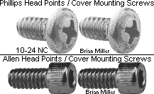 Phillips Head
and Hex Socket (Allen) Head Screws with split lock washers to fasten ignition
points and/or points cover on Kohler engines. Fits Kohler engine models
K90/K91, K141, K161/K160, KV161,
L160/L161, L181,
K181, K241, K301, K321, K330/K331, K341, K361, KT17 (first design), KT17
Series II, KT19 (first design) KT19 Series II, KT21, K482, K532 and K582.
These type of screw heads make for easier fastening of points and points
cover to engine block in hard-to-reach places than the OEM slotted head screws
on garden tractors with a
transverse engine as listed above. Each screw replaces
discontinued Kohler part # X-131-1-S. Phillips Head
and Hex Socket (Allen) Head Screws with split lock washers to fasten ignition
points and/or points cover on Kohler engines. Fits Kohler engine models
K90/K91, K141, K161/K160, KV161,
L160/L161, L181,
K181, K241, K301, K321, K330/K331, K341, K361, KT17 (first design), KT17
Series II, KT19 (first design) KT19 Series II, KT21, K482, K532 and K582.
These type of screw heads make for easier fastening of points and points
cover to engine block in hard-to-reach places than the OEM slotted head screws
on garden tractors with a
transverse engine as listed above. Each screw replaces
discontinued Kohler part # X-131-1-S.
High Quality Adjustable Chevy (GM) Ignition Points with Stiff Spring for
Quick Reaction at open RPM. Use on Kohler K-series K241, K301, K321,
K341, K361 competition pulling engines only. NOTE: Not recommended for
use on lawn and garden equipment engines due to long exposure to dust and
debris, which can contaminate points contacts and cause a misfire. IMPORTANT:
Sometimes oxidation will form on new points contacts from sitting in storage,
even when sealed with plastic. This is very common with small engine and
automotive ignition points. Therefore, do not use sanding material, such
as sandpaper or emery cloth, to clean any electrical contacts! These will
leave a gritty residue between the contacts, causing a faulty connection.
Instead, while the points is installed and the contacts are closed under
pressure, use a [preferably clean]
TIP: To prevent small Phillips- or slotted-head screws from falling out of the screwdriver tip when installing in a hard to reach place, first of all, use the correct size screwdriver that fits the screw head, and for ordinary steel screws, temporarily magnetize the screwdriver by rubbing a magnet several times along the length of the shank, or for stainless steel screws, apply a dab of automotive grease in the head of the screw. |
|
 Ignition Points
Pushrods. Fits Kohler K141, K160/K161,
KV161,
L160/L161, L181 and
K181. NOTE: New OEM Kohler K-series engine models points pushrods for
these engines measures 1.265" in length, and a used pushrod must be no less
than 1.205" in length. Measure yours accurately with a
dial or
digital caliper to determine if it needs replacing. Or
improve engine performance and longevity with A-1 Miller's custom-made
Electronic Ignition Conversion
Kit! Ignition Points
Pushrods. Fits Kohler K141, K160/K161,
KV161,
L160/L161, L181 and
K181. NOTE: New OEM Kohler K-series engine models points pushrods for
these engines measures 1.265" in length, and a used pushrod must be no less
than 1.205" in length. Measure yours accurately with a
dial or
digital caliper to determine if it needs replacing. Or
improve engine performance and longevity with A-1 Miller's custom-made
Electronic Ignition Conversion
Kit!
Ignition Points Pushrods. Fits K90/K91, K241, K301, K321, K341, K361, K482, K532 and K582 engines. NOTE: New OEM Kohler points pushrods for these engines measures 1.550" in length, and a used pushrod must be no less than 1.500" in length. Measure yours accurately with a dial or digital caliper to determine if it needs replacing. Or improve engine performance and longevity with A-1 Miller's custom-made Electronic Ignition Conversion Kit!
IMPORTANT! Running an engine with insufficient or severely retarded ignition timing will cause accelerated internal wear and lead to oil burning over time. When the timing is retarded (spark occurs too late before the piston reaches top dead center), the fuel mixture does not have time to burn completely inside the combustion chamber, and some it exits out the exhaust. This results in several cascading issues:
|
|
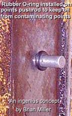  3/16" I.D. Neoprene Rubber O-Ring. Installs
on points pushrod close to engine block, allowing any seepage of crankcase
oil to drip down, staying off points contacts. Fits Kohler engine models
K90/K91, K141, K161/K160,
KV161,
L160/L161, L181, K181,
K241, K301, K321, K341, K361, K482, K532 and K582. But if the ignition points
pushrod hole is excessively worn, this will effect the ignition timing as
well, and the block will need to be machined for installation of a bronze
sleeve bushing, or the hole can be plugged, and solid state or a custom-made
flywheel- or
crank-trigger electronic ignition system
can be installed. (The translucent silicone rubber diaphragm seal (part
# 220074-S) is no longer available from Kohler.)
[Return to previous paragraph, section
or website] 3/16" I.D. Neoprene Rubber O-Ring. Installs
on points pushrod close to engine block, allowing any seepage of crankcase
oil to drip down, staying off points contacts. Fits Kohler engine models
K90/K91, K141, K161/K160,
KV161,
L160/L161, L181, K181,
K241, K301, K321, K341, K361, K482, K532 and K582. But if the ignition points
pushrod hole is excessively worn, this will effect the ignition timing as
well, and the block will need to be machined for installation of a bronze
sleeve bushing, or the hole can be plugged, and solid state or a custom-made
flywheel- or
crank-trigger electronic ignition system
can be installed. (The translucent silicone rubber diaphragm seal (part
# 220074-S) is no longer available from Kohler.)
[Return to previous paragraph, section
or website]
|
|
 Ignition
Points Cover Gaskets. Fits Kohler engine models K90/K91, K141, K160/K161,
KV161,
L160/L161, L181, K181,
K241, K301, K321, K330/K331, K341, K361, KT17 (first design), KT17 Series
II, KT19 (first design) KT19 Series II, KT21, K482, K532 and K582. Protects
points contacts from dust, dirt and water contamination. Also, use this part
when converting from Breakerless Ignition to battery-powered points/condenser
ignition. Ignition
Points Cover Gaskets. Fits Kohler engine models K90/K91, K141, K160/K161,
KV161,
L160/L161, L181, K181,
K241, K301, K321, K330/K331, K341, K361, KT17 (first design), KT17 Series
II, KT19 (first design) KT19 Series II, KT21, K482, K532 and K582. Protects
points contacts from dust, dirt and water contamination. Also, use this part
when converting from Breakerless Ignition to battery-powered points/condenser
ignition.
|
|
 Grommet
for Ignition Points Cover/Wire. Fits Kohler engine models K90/K91, K141,
K161/K160, KV161,
L160/L161, L181, K181,
K241, K301, K321, K330/K331, K341, K361, KT17, KT17 Series II, KT19 and KT19
Series II, KT21, K482, K532 and K582. Prevents dust and dirt from contaminating
points contacts, and protects points wire from rubbing/chafing against points
cover or use this part when converting from Breakerless Ignition to
battery-powered points/condenser ignition. FYI:
RTV Silicone Adhesive Sealant will serve the same
purpose. Grommet
for Ignition Points Cover/Wire. Fits Kohler engine models K90/K91, K141,
K161/K160, KV161,
L160/L161, L181, K181,
K241, K301, K321, K330/K331, K341, K361, KT17, KT17 Series II, KT19 and KT19
Series II, KT21, K482, K532 and K582. Prevents dust and dirt from contaminating
points contacts, and protects points wire from rubbing/chafing against points
cover or use this part when converting from Breakerless Ignition to
battery-powered points/condenser ignition. FYI:
RTV Silicone Adhesive Sealant will serve the same
purpose.
|
|
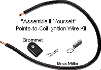 "Assemble It
Yourself" Points-to-Ignition Coil Wire Kit. Replace OEM wire with
frayed/cracked insulation and/or broken connector(s) to prevent a short circuit
and/or engine misfire. Or use this when converting from Breakerless Ignition
to points and condenser ignition. Fits Kohler engines with battery-powered
ignition, models K90/K91, K141, K161/K160,
KV161,
L160/L161, L181,
K181, K241, K301, K321, K330/K331, K341, K361, KT17 (first design), KT17
Series II, KT19 (first design) KT19 Series II, KT21, K482, K532 and K582.
Includes 22" length (cut to desired length) x #16 gauge (AWG) insulated stranded
copper wire and two uninstalled crimp connectors. Requires use of
electrical connector crimping pliers. High quality A-1
Miller's parts. Replaces Kohler part # A-230371-S. "Assemble It
Yourself" Points-to-Ignition Coil Wire Kit. Replace OEM wire with
frayed/cracked insulation and/or broken connector(s) to prevent a short circuit
and/or engine misfire. Or use this when converting from Breakerless Ignition
to points and condenser ignition. Fits Kohler engines with battery-powered
ignition, models K90/K91, K141, K161/K160,
KV161,
L160/L161, L181,
K181, K241, K301, K321, K330/K331, K341, K361, KT17 (first design), KT17
Series II, KT19 (first design) KT19 Series II, KT21, K482, K532 and K582.
Includes 22" length (cut to desired length) x #16 gauge (AWG) insulated stranded
copper wire and two uninstalled crimp connectors. Requires use of
electrical connector crimping pliers. High quality A-1
Miller's parts. Replaces Kohler part # A-230371-S.
|
|
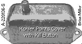 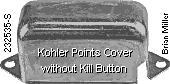 Ignition Points Covers. Protects points from dust, dirt
and water contamination. Replace damaged or missing points cover. Fits Kohler
engine models K90/K91, K141, K161/K160,
KV161,
L160/L161, L181,
K181, K241, K301, K321, K330/K331, K341, K361, KT17 (first design), KT17
Series II, KT19 (first design) KT19 Series II, KT21, K482, K532 and K582. Ignition Points Covers. Protects points from dust, dirt
and water contamination. Replace damaged or missing points cover. Fits Kohler
engine models K90/K91, K141, K161/K160,
KV161,
L160/L161, L181,
K181, K241, K301, K321, K330/K331, K341, K361, KT17 (first design), KT17
Series II, KT19 (first design) KT19 Series II, KT21, K482, K532 and K582.
|
|
  3/16" Steel Plug for Kohler
Ignition Points Pushrod Hole. Fits Kohler engine models K90/K91,
K141, K160/K161, KV161,
L160/L161, L181,
K181, K241, K301, K321, K341, K361, and K482, K532, K582 (with an unworn
points pushrod hole). Use this part (to prevent eventual oil leakage) when
converting engine to electronic ignition. (Listed in this website.) Remove
points cover, points and OEM pushrod, and install this plug in the pushrod
hole with a medium size hammer. Plug should fit tight in hole, but if it
fits loose, create knurled/raised ridges on the plug with a sharp, flat cold
chisel and hammer, and apply silicone sealant on plug when installing in
the block. No need to reinstall cover and points. NOTE: The alternative
to using this plug is to remove the ignition points and points pushrod, and
place the pushrod on a hard, flat surface, and use a hammer and sharp flat
cold chisel to lightly create knurled raised marks midway on the pushrod.
Then reinstall the knurled pushrod in the engine block with the hammer. Or
a
20 penny common nail cut off to 1/2" length and the end
ground to a bevel will serve the same purpose. The knurled ridges will retain
the pushrod in the hole. Replaces Kohler part # X-702-1 (brass welch
plug). OEM Briggs & Stratton part #'s 231143, 692882. $6.00 each,
plus shipping & handling. [Return
to previous paragraph, section or website] 3/16" Steel Plug for Kohler
Ignition Points Pushrod Hole. Fits Kohler engine models K90/K91,
K141, K160/K161, KV161,
L160/L161, L181,
K181, K241, K301, K321, K341, K361, and K482, K532, K582 (with an unworn
points pushrod hole). Use this part (to prevent eventual oil leakage) when
converting engine to electronic ignition. (Listed in this website.) Remove
points cover, points and OEM pushrod, and install this plug in the pushrod
hole with a medium size hammer. Plug should fit tight in hole, but if it
fits loose, create knurled/raised ridges on the plug with a sharp, flat cold
chisel and hammer, and apply silicone sealant on plug when installing in
the block. No need to reinstall cover and points. NOTE: The alternative
to using this plug is to remove the ignition points and points pushrod, and
place the pushrod on a hard, flat surface, and use a hammer and sharp flat
cold chisel to lightly create knurled raised marks midway on the pushrod.
Then reinstall the knurled pushrod in the engine block with the hammer. Or
a
20 penny common nail cut off to 1/2" length and the end
ground to a bevel will serve the same purpose. The knurled ridges will retain
the pushrod in the hole. Replaces Kohler part # X-702-1 (brass welch
plug). OEM Briggs & Stratton part #'s 231143, 692882. $6.00 each,
plus shipping & handling. [Return
to previous paragraph, section or website]
|
|
| NOTE:
If a small engine idles well, but fails to rev up or runs erratically at
higher speeds (like it hits and misses, pops and backfires), then chances
are, it needs a new condenser/capacitor. And always install a condenser with
the wire or terminal facing downward so rain water and/or when washing off
engine, water will not enter inside condenser, ruining it. With water inside
the condenser, this will cause the engine to run erratically when revved
up.
|
|
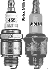 High Quality Copper Core/Non-Resistor Spark Plugs. Designed
for Kohler engine models K90/K91, smaller flathead Briggs & Stratton
and Tecumseh engines, most 2-cycle small engines and most chainsaws. Along
with a metal core spark wire, copper core spark plugs provide a stronger
spark that allow the ignition coil to operate cooler, last longer and provide
the highest possible energy to ensure maximum ignition potential. For best
engine performance and longevity of the coil, set gap at .025" with a
self-energizing magneto or solid state electronic ignition system, .035"
with a full size battery-powered ignition coil, and .060" with a
high-output/performance battery-powered coil. 14mm threads x 3/8" thread
reach, flat washer seat. Replaces Briggs and Stratton part # 802592S. High Quality Copper Core/Non-Resistor Spark Plugs. Designed
for Kohler engine models K90/K91, smaller flathead Briggs & Stratton
and Tecumseh engines, most 2-cycle small engines and most chainsaws. Along
with a metal core spark wire, copper core spark plugs provide a stronger
spark that allow the ignition coil to operate cooler, last longer and provide
the highest possible energy to ensure maximum ignition potential. For best
engine performance and longevity of the coil, set gap at .025" with a
self-energizing magneto or solid state electronic ignition system, .035"
with a full size battery-powered ignition coil, and .060" with a
high-output/performance battery-powered coil. 14mm threads x 3/8" thread
reach, flat washer seat. Replaces Briggs and Stratton part # 802592S.
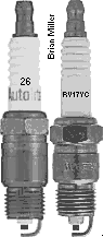 High Quality Copper
Core/Non-Resistor Spark Plugs. Designed for Kohler opposed twin-cylinder
flathead engine models MV16, KT17, KT17 Series II, KT19 and KT19 Series II,
KT21, M18, MV18, M20 and MV20. Also designed for 1971-1989 Chevrolet and
GMC L4, L6, V6 and V8 engines. Along with a metal core spark wire, copper
core spark plugs provide a stronger spark that allow the ignition coil to
operate cooler, last longer and provide the highest possible energy to ensure
maximum ignition potential. For best small engine performance and longevity
of the coil, set gap at .025" with a self-energizing magneto or solid state
electronic ignition system, .035" with a full size battery-powered ignition
coil, and .060" with a high-output/performance battery-powered coil. 14mm
threads x 15/32" thread reach, tapered seat. High Quality Copper
Core/Non-Resistor Spark Plugs. Designed for Kohler opposed twin-cylinder
flathead engine models MV16, KT17, KT17 Series II, KT19 and KT19 Series II,
KT21, M18, MV18, M20 and MV20. Also designed for 1971-1989 Chevrolet and
GMC L4, L6, V6 and V8 engines. Along with a metal core spark wire, copper
core spark plugs provide a stronger spark that allow the ignition coil to
operate cooler, last longer and provide the highest possible energy to ensure
maximum ignition potential. For best small engine performance and longevity
of the coil, set gap at .025" with a self-energizing magneto or solid state
electronic ignition system, .035" with a full size battery-powered ignition
coil, and .060" with a high-output/performance battery-powered coil. 14mm
threads x 15/32" thread reach, tapered seat.
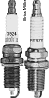 High Quality Copper
Core/Non-Resistor Spark Plugs. Designed for most makes and models of
OHV aluminum block single- and V-twin air-cooled small engines. Along with
a metal core spark wire, copper core spark plugs provide a stronger spark
that allow the ignition coil to operate cooler, last longer and provide the
highest possible energy to ensure maximum ignition potential. For best engine
performance and longevity of the coil, set gap at .025" with a self-energizing
magneto or solid state electronic ignition system, .035" with a full size
battery-powered ignition coil, and .060" with a high-output/performance
battery-powered coil. 14mm threads x 5/8" thread reach, flat washer seat. High Quality Copper
Core/Non-Resistor Spark Plugs. Designed for most makes and models of
OHV aluminum block single- and V-twin air-cooled small engines. Along with
a metal core spark wire, copper core spark plugs provide a stronger spark
that allow the ignition coil to operate cooler, last longer and provide the
highest possible energy to ensure maximum ignition potential. For best engine
performance and longevity of the coil, set gap at .025" with a self-energizing
magneto or solid state electronic ignition system, .035" with a full size
battery-powered ignition coil, and .060" with a high-output/performance
battery-powered coil. 14mm threads x 5/8" thread reach, flat washer seat.
|
|
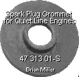 Spark Plug
Grommet. Fits Kohler (Quiet Line) engine models K181AQS, M8, K241AQS,
K301AQS, K321AQS and K341AQS. Fastens directly on spark plug in air duct
shield (sheet metal) over cylinder head to help cool the head better. Made
of neoprene rubber. Spark Plug
Grommet. Fits Kohler (Quiet Line) engine models K181AQS, M8, K241AQS,
K301AQS, K321AQS and K341AQS. Fastens directly on spark plug in air duct
shield (sheet metal) over cylinder head to help cool the head better. Made
of neoprene rubber.
|
|
| Indexing
Washers for Flat Seat Spark Plugs with 14mm Threads. Positions spark
plug with the open/exposed gap facing the center of the piston in combustion
chamber of flathead engines for up to 10% more horsepower and torque when
using tractor under extreme conditions, such as heavy mowing, garden plowing,
pushing/blowing snow or competition pulling. To know exactly where the open
gap is when the spark plug is installed in the head, place a mark (line)
with a permanent ink marker
(Sharpie,
Magic Marker,
Marks-A-Lot, etc.) on the porcelain in-line with the open
gap at the tip of the spark plug as shown in the photo to the right ->.
Also, leave the original compression washer on the spark plug and add the
indexing washer(s) as required, tighten spark plug with ink mark on
porcelain/open gap facing near center of the piston. Made of hardened steel.
Available in the following thicknesses: .005", .010" and .015".
.75¢ each, plus shipping & handling.
|
|
    High Quality Universal Switches. Designed for use with
Self-Energizing Magneto Ignition, Solid State Ignition, OEM Solid State
Ignition (SSI) for Tecumseh's Cast Iron Block Engines, or with OEM Kohler
Breakerless Ignition. These can be used on virtually any small engine
installed on lawn and garden equipment, garden tillers, go-karts, chainsaws,
log splitters, portable air compressors, portable generators/welders, portable
water pumps, etc. with a magneto or solid state ignition, and a recoil/rope
starter or a push button starter switch, if engine is equipped with an
electric starter.
Very durable, tough switches. High Quality Universal Switches. Designed for use with
Self-Energizing Magneto Ignition, Solid State Ignition, OEM Solid State
Ignition (SSI) for Tecumseh's Cast Iron Block Engines, or with OEM Kohler
Breakerless Ignition. These can be used on virtually any small engine
installed on lawn and garden equipment, garden tillers, go-karts, chainsaws,
log splitters, portable air compressors, portable generators/welders, portable
water pumps, etc. with a magneto or solid state ignition, and a recoil/rope
starter or a push button starter switch, if engine is equipped with an
electric starter.
Very durable, tough switches.
|
|
 High
Quality Universal Switches for Battery-Powered Ignition and Electrical
Accessories. Very durable, tough switches. Either can be used for
ignition, lights,
electric fuel
pump, electric PTO clutch, etc. When used for ignition, use with
push button starter switch (listed below). Terminals or wires on switches
listed below makes contact when in the ON position.
Can be used on virtually anything that have a battery-powered ignition or
electrical system, such as: garden tractors, go-karts, competition pulling
tractors, small motorized vehicles, mini-rods, hot-rods, farm tractors,
automobiles, etc. Each can be mounted in dashboard, instrument panel, engine
control panel, etc. High
Quality Universal Switches for Battery-Powered Ignition and Electrical
Accessories. Very durable, tough switches. Either can be used for
ignition, lights,
electric fuel
pump, electric PTO clutch, etc. When used for ignition, use with
push button starter switch (listed below). Terminals or wires on switches
listed below makes contact when in the ON position.
Can be used on virtually anything that have a battery-powered ignition or
electrical system, such as: garden tractors, go-karts, competition pulling
tractors, small motorized vehicles, mini-rods, hot-rods, farm tractors,
automobiles, etc. Each can be mounted in dashboard, instrument panel, engine
control panel, etc.
|
|
 High
Quality Universal push button switches. Each can be mounted in pedestal,
dashboard, instrument panel, engine control panel, flywheel shroud, etc. High
Quality Universal push button switches. Each can be mounted in pedestal,
dashboard, instrument panel, engine control panel, flywheel shroud, etc.
|
|
 High Quality Universal 3-Position OFF-ON-START
MAGNETO Ignition Key Switch. Designed specifically for Self-Energizing
Magneto Ignition, Solid State Ignition, OEM Solid State Ignition (SSI) for
Tecumseh's Cast Iron Block Engines, or with OEM Kohler Breakerless
Ignition. Can be used for various makes and models of riding mowers,
lawn & garden tractors, garden tractors and various small engine equipment
with magneto or solid state ignition. Identification of 5 blade terminals:
B = Battery (+); G = Ground (terminal is grounded to body of
switch); L = Lights (use a separate OFF-ON switch connected to this
terminal to power an electric PTO clutch); M = Magneto (Ignition);
S = Solenoid (small terminal). Key positions: OFF position makes contact
with M+G; IGNITION position makes contact with B+L; START position makes
contact with B+S. Each terminal identified for correct wiring connections.
IMPORTANT: Use with a starter solenoid/relay to crank the engine to prevent
burning out internal contacts in switch. NOTE: If engine is equipped with
an alternator/stator charging system, the center terminal on the voltage
rectifier/regulator connects to the positive (+) battery post. If using an
ammeter/amp gauge, connect the gauge/meter to the positive (+) battery post,
then to the B terminal on the switch. Trace the wires on your tractor/equipment
to see if they match the terminals on this switch. If they don't match, the
plug-in spade connectors/wires can be rearranged in the plastic connector
housing to match the corresponding terminals on the switch. To do this, use
a small flat blade screwdriver to depress the locking tab/tang so the plug-in
connector can be pulled out from the plastic connector housing. Bend the
locking tab/tang up slightly before reinserting it in the plastic connector
so it will be secured in place. Or for a universal application, use #250
slip-on female spade crimp-type wire connectors. Requires 5/8" diameter mounting
hole. High Quality Universal 3-Position OFF-ON-START
MAGNETO Ignition Key Switch. Designed specifically for Self-Energizing
Magneto Ignition, Solid State Ignition, OEM Solid State Ignition (SSI) for
Tecumseh's Cast Iron Block Engines, or with OEM Kohler Breakerless
Ignition. Can be used for various makes and models of riding mowers,
lawn & garden tractors, garden tractors and various small engine equipment
with magneto or solid state ignition. Identification of 5 blade terminals:
B = Battery (+); G = Ground (terminal is grounded to body of
switch); L = Lights (use a separate OFF-ON switch connected to this
terminal to power an electric PTO clutch); M = Magneto (Ignition);
S = Solenoid (small terminal). Key positions: OFF position makes contact
with M+G; IGNITION position makes contact with B+L; START position makes
contact with B+S. Each terminal identified for correct wiring connections.
IMPORTANT: Use with a starter solenoid/relay to crank the engine to prevent
burning out internal contacts in switch. NOTE: If engine is equipped with
an alternator/stator charging system, the center terminal on the voltage
rectifier/regulator connects to the positive (+) battery post. If using an
ammeter/amp gauge, connect the gauge/meter to the positive (+) battery post,
then to the B terminal on the switch. Trace the wires on your tractor/equipment
to see if they match the terminals on this switch. If they don't match, the
plug-in spade connectors/wires can be rearranged in the plastic connector
housing to match the corresponding terminals on the switch. To do this, use
a small flat blade screwdriver to depress the locking tab/tang so the plug-in
connector can be pulled out from the plastic connector housing. Bend the
locking tab/tang up slightly before reinserting it in the plastic connector
so it will be secured in place. Or for a universal application, use #250
slip-on female spade crimp-type wire connectors. Requires 5/8" diameter mounting
hole.
|
|
  Universal Wiring Harness with Plastic Connector Housing
and Slide-On Connectors. Replace damaged entire connector, terminals
and wiring, use as new wiring harness on a custom-made project, or use this
part when converting from Breakerless Ignition to battery-powered
points/condenser ignition. Fits universal OFF-ON-START key switches listed
above and other key switches with same terminal configuration. Three terminals
in this part will also fit the OEM Cub Cadet garden tractor OFF-ON-START
key switch listed above. 18" length color-coded wires for easy identification.
$13.00 each, plus shipping & handling. Universal Wiring Harness with Plastic Connector Housing
and Slide-On Connectors. Replace damaged entire connector, terminals
and wiring, use as new wiring harness on a custom-made project, or use this
part when converting from Breakerless Ignition to battery-powered
points/condenser ignition. Fits universal OFF-ON-START key switches listed
above and other key switches with same terminal configuration. Three terminals
in this part will also fit the OEM Cub Cadet garden tractor OFF-ON-START
key switch listed above. 18" length color-coded wires for easy identification.
$13.00 each, plus shipping & handling.
Electrical Plastic Connector Housing Only. Replace damaged connector housing when the brass slide-on spade crimp wire connectors (listed below) are in good condition. Fits universal OFF-ON-START key switches listed above and other key switches with same terminal configuration. Three slots in this part will also fit the OEM Cub Cadet garden tractor OFF-ON-START key switch listed above. Requires 1/4" width slide-on brass spade crimp wire connectors with locking tab/tang below. $8.00 each, plus shipping & handling.
|
|
| FYI - Magneto Coils - To test for
continually of an ignition coil (to see if it's in good condition), use a
multimeter set on the ohm () resistance. To test
the secondary winding (this is the one that usually burns out), insert one
of the multimeter's probes into the spark plug terminal of the coil, contacting
the metal inside the terminal. And touch the second probe of the meter to
the ignition coil's negative (–) terminal. (This is the one not connected
to the primary winding and resistor.) Depending on the type of coil (magneto,
compact, standard size or high output/performance), the meter should read
6,000 to 15,000 ohms. If it does not, the secondary winding is faulty and
the coil needs to be replaced. |
|
 Magneto Armature
Ignition Coil. Fits Kohler engine model K91 with self-energizing magneto
ignition. May not fit model K90 with magneto ignition. Spark plug wire (not
included) inserts into front/outward curvature of coil. Reuse OEM spark plug
wire. For best engine performance and longevity of the coil, set spark plug
gap at .025" with this coil. 1.0 ohm internal primary resistor. NOTE:
This coil should produce a stronger spark when used with the
Universal Solid State Electronic Ignition
Module. Or the engine can be
converted to battery-powered
ignition. IMPORTANT: Use a new copper core/non-resistor AC Delco,
Autolite or Champion spark plug of the correct type gapped at .025" for longer
coil life. Use of a resistor
type spark plug will void warranty. New Old Stock. Discontinued OEM
Kohler part # 220435-S. $144.00 each, plus shipping & handling. Magneto Armature
Ignition Coil. Fits Kohler engine model K91 with self-energizing magneto
ignition. May not fit model K90 with magneto ignition. Spark plug wire (not
included) inserts into front/outward curvature of coil. Reuse OEM spark plug
wire. For best engine performance and longevity of the coil, set spark plug
gap at .025" with this coil. 1.0 ohm internal primary resistor. NOTE:
This coil should produce a stronger spark when used with the
Universal Solid State Electronic Ignition
Module. Or the engine can be
converted to battery-powered
ignition. IMPORTANT: Use a new copper core/non-resistor AC Delco,
Autolite or Champion spark plug of the correct type gapped at .025" for longer
coil life. Use of a resistor
type spark plug will void warranty. New Old Stock. Discontinued OEM
Kohler part # 220435-S. $144.00 each, plus shipping & handling. |
|
   Magneto Armature
Ignition Coils. Fits various Kohler K-series engine models
KV161,
L160/L161, L181,
K181, K241, K301, K321, K330/K331 and K341 with points, condenser/capacitor
and coil under flywheel. Common with Kohler engines mounted to a generator
or welder. Also fits most small- and medium-frame aluminum block Tecumseh
engines with points, condenser and coil under flywheel. NOTES: These coils
should produce a stronger spark when used with the
Universal Solid State Electronic Ignition
Module. Also, each coil listed below can be substituted for the obsolete
OEM Kohler part # 275756 coil by grinding down the laminations on the armature
to .405" x .405" square. Do not grind out inside of coil! To secure coil
on the armature, bend one lamination over end of coil. Or engine could be
converted to the more reliable
battery-powered ignition system. 1.0 ohm internal primary resistor.
Dimensions of each coil: 1.700" O.D. x 1.080" length x .405" square hole.
How
magneto coils generate a spark. IMPORTANT: Use a new copper
core/non-resistor AC Delco, Autolite or Champion spark plug of the correct
type gapped at .025" for longer coil life. Use of a
resistor type spark plug
will void warranty. And being all older magneto coil spark plug wires
have a metal core, save it off your old coil. With a 12 volt battery coil
tower terminal and boot installed, it can be used for battery ignition. Magneto Armature
Ignition Coils. Fits various Kohler K-series engine models
KV161,
L160/L161, L181,
K181, K241, K301, K321, K330/K331 and K341 with points, condenser/capacitor
and coil under flywheel. Common with Kohler engines mounted to a generator
or welder. Also fits most small- and medium-frame aluminum block Tecumseh
engines with points, condenser and coil under flywheel. NOTES: These coils
should produce a stronger spark when used with the
Universal Solid State Electronic Ignition
Module. Also, each coil listed below can be substituted for the obsolete
OEM Kohler part # 275756 coil by grinding down the laminations on the armature
to .405" x .405" square. Do not grind out inside of coil! To secure coil
on the armature, bend one lamination over end of coil. Or engine could be
converted to the more reliable
battery-powered ignition system. 1.0 ohm internal primary resistor.
Dimensions of each coil: 1.700" O.D. x 1.080" length x .405" square hole.
How
magneto coils generate a spark. IMPORTANT: Use a new copper
core/non-resistor AC Delco, Autolite or Champion spark plug of the correct
type gapped at .025" for longer coil life. Use of a
resistor type spark plug
will void warranty. And being all older magneto coil spark plug wires
have a metal core, save it off your old coil. With a 12 volt battery coil
tower terminal and boot installed, it can be used for battery ignition.
|
|
 Magneto Armature
Ignition Stator/Coil with Small Charging Coil. Fits various Kohler engines
with stator/coil mounted on bearing plate underneath flywheel with two magnets
inside flywheel. Common with various generator engines. Coil has 1.0 ohm
internal primary resistor. NOTE: This coil should produce a stronger spark
when used with the Universal Solid State Electronic
Ignition Module. Or the engine could be
converted to battery-powered
ignition.
How
magneto coils generate a spark. IMPORTANT: Use a new copper
core/non-resistor AC Delco, Autolite or Champion spark plug of the correct
type gapped at .025" for longer coil life. Use of a
resistor type spark plug
will void warranty. Magneto Armature
Ignition Stator/Coil with Small Charging Coil. Fits various Kohler engines
with stator/coil mounted on bearing plate underneath flywheel with two magnets
inside flywheel. Common with various generator engines. Coil has 1.0 ohm
internal primary resistor. NOTE: This coil should produce a stronger spark
when used with the Universal Solid State Electronic
Ignition Module. Or the engine could be
converted to battery-powered
ignition.
How
magneto coils generate a spark. IMPORTANT: Use a new copper
core/non-resistor AC Delco, Autolite or Champion spark plug of the correct
type gapped at .025" for longer coil life. Use of a
resistor type spark plug
will void warranty.
|
|
 Magneto Armature
Ignition Coil. Fits various Kohler engine models K141, K161,
KV161,
L160/L161, L181 and
K181 with coil mounted on U-shaped ignition armature on bearing plate underneath
flywheel with magnet rotor on crankshaft. Also fits various larger cast iron
block Clinton engines with coil/armature mounted on cylinder, above flywheel.
Spark plug wire not included. For best engine performance and longevity of
the coil, set spark plug gap at .025" with this coil. NOTE: This coil
should produce a stronger spark when used with the
Universal Solid State Electronic Ignition
Module. Or the engine could be
converted to battery-powered
ignition. IMPORTANT: Use a new copper core/non-resistor Autolite or Champion
spark plug of the correct type gapped at .025" for longer coil life. Use
of a resistor type
spark plug will void warranty. Dimensions: 1.750" diameter x 1.450"
length x .505" square hole.
How
magneto coils generate a spark. Magneto Armature
Ignition Coil. Fits various Kohler engine models K141, K161,
KV161,
L160/L161, L181 and
K181 with coil mounted on U-shaped ignition armature on bearing plate underneath
flywheel with magnet rotor on crankshaft. Also fits various larger cast iron
block Clinton engines with coil/armature mounted on cylinder, above flywheel.
Spark plug wire not included. For best engine performance and longevity of
the coil, set spark plug gap at .025" with this coil. NOTE: This coil
should produce a stronger spark when used with the
Universal Solid State Electronic Ignition
Module. Or the engine could be
converted to battery-powered
ignition. IMPORTANT: Use a new copper core/non-resistor Autolite or Champion
spark plug of the correct type gapped at .025" for longer coil life. Use
of a resistor type
spark plug will void warranty. Dimensions: 1.750" diameter x 1.450"
length x .505" square hole.
How
magneto coils generate a spark.
|
|
 Armature Ignition
Coil with Integrated Solid State Electronic Module. Fits Kohler Magnum
engine model M8. NOTE: Install this coil with spark plug wire facing engine
block as shown in photo to the right ->. Set the air gap/clearance between
the magnet in the flywheel and armature laminations with a business card
or a .010" or .25mm brass feeler gauge. The .010" or .25mm gap produces a
stronger magnetic field through the coil to generate more electricity for
a stronger spark, and so the engine won't misfire. IMPORTANT: Use
a new copper core/non-resistor Autolite or Champion spark plug of the correct
type gapped at .025" for longer coil life. Use of a
resistor type spark plug will void
warranty. And being all older magneto coil spark plug wires have a metal
core, save it off your old coil. With a 12 volt battery coil tower terminal
and boot installed, it can be used for battery ignition. Armature Ignition
Coil with Integrated Solid State Electronic Module. Fits Kohler Magnum
engine model M8. NOTE: Install this coil with spark plug wire facing engine
block as shown in photo to the right ->. Set the air gap/clearance between
the magnet in the flywheel and armature laminations with a business card
or a .010" or .25mm brass feeler gauge. The .010" or .25mm gap produces a
stronger magnetic field through the coil to generate more electricity for
a stronger spark, and so the engine won't misfire. IMPORTANT: Use
a new copper core/non-resistor Autolite or Champion spark plug of the correct
type gapped at .025" for longer coil life. Use of a
resistor type spark plug will void
warranty. And being all older magneto coil spark plug wires have a metal
core, save it off your old coil. With a 12 volt battery coil tower terminal
and boot installed, it can be used for battery ignition.
 Armature Ignition Coil with
Integrated Solid State Electronic Module. Fits Kohler Magnum engine models
M10, M12, M14 and M16. NOTE: Install this coil with spark plug wire facing
engine block as shown in photo to the right ->. Set the air gap/clearance
between the magnet in the flywheel and armature laminations with a business
card or a .010" or .25mm brass feeler gauge. The .010" or .25mm gap produces
a stronger magnetic field through the coil to generate more electricity for
a stronger spark, and so the engine won't misfire. IMPORTANT: Use
a new copper core/non-resistor Autolite or Champion spark plug of the correct
type gapped at .025" for longer coil life. Use of a
resistor type spark plug will void
warranty. And being all older magneto coil spark plug wires have a metal
core, save it off your old coil. With a 12 volt battery coil tower terminal
and boot installed, it can be used for battery ignition. Armature Ignition Coil with
Integrated Solid State Electronic Module. Fits Kohler Magnum engine models
M10, M12, M14 and M16. NOTE: Install this coil with spark plug wire facing
engine block as shown in photo to the right ->. Set the air gap/clearance
between the magnet in the flywheel and armature laminations with a business
card or a .010" or .25mm brass feeler gauge. The .010" or .25mm gap produces
a stronger magnetic field through the coil to generate more electricity for
a stronger spark, and so the engine won't misfire. IMPORTANT: Use
a new copper core/non-resistor Autolite or Champion spark plug of the correct
type gapped at .025" for longer coil life. Use of a
resistor type spark plug will void
warranty. And being all older magneto coil spark plug wires have a metal
core, save it off your old coil. With a 12 volt battery coil tower terminal
and boot installed, it can be used for battery ignition.
|
|
| IMPORTANT:
Most failures of a battery-powered ignition coils and/or electronic ignition
control modules are caused by either the use of suppression/carbon-core spark
plug wire(s), resistor-type spark plug(s) [NGK spark plugs], or overcharging
of the electrical system due to a defective voltage rectifier/regulator or
defective [automotive] battery. Therefore, if it's not already equipped,
it's best to install an ammeter/amp gauge to monitor the charging system.
Also, any coil will burn up if the ignition switch is left on with the points
closed for more than a few minutes with the engine not running. To prevent
this from possibly happening and/or for security reasons, use an OFF-ON key
switch and/or a master disconnect switch with a removable key instead of
just a toggle switch to power the ignition system. Also, the coil could burn
up if the charging system continually overcharge due to a defective voltage
rectifier/regulator or a defective [automotive] battery.
|
|
High Quality,
High-Performance Metal Core 7mm Spark Plug Wire Assemblies Listed Below.
Universal design for many applications. Along with a copper core spark plug,
metal core spark wires provide a stronger spark that allow the ignition coil
to operate cooler, last longer and provide the highest possible energy to
ensure maximum ignition potential. Replace defective coil-to-spark plug wire
or use either of the parts listed below when converting from Breakerless
Ignition or magneto ignition to battery-powered points/condenser ignition.
Suitable for general lawn & garden equipment, small motorized vehicles
or competition garden pulling tractor engines. Fits Kohler engine models
K141, K160/K161, KV161,
L160/L161, L181, K181,
K241, K301, K321, K330/K331, K341, K361, KT17 (first design), KT17 Series
II, KT19 (first design) KT19 Series II, KT21, K482, K532, K582 and K660/K662
(with wires cut to desired length) and other makes and models of small engines
with a battery-powered ignition system. Don't be fooled by the dark color,
these wires have a metal core that provide 100% voltage to the spark plug
for a strong spark to extend the life of the coil. Copper or metal wire delivers
maximum energy with zero ohm resistance to the spark plug. (FYI - Most OEM
automotive or brightly-colored coil-to-spark plug wires have a suppression/carbon
core that deliver about 40%-50% voltage to the spark plug at peak demand,
which is at open RPM, they've been known to burn up a good coil.) Solid metal
terminals for maximum conductivity and corrosion resistance. Snug-fitting
quality rubber boots keep out dirt and moisture for reliable engine start
up. Engineered for reliability and long life. Spring-lock terminals insure
positive and secure connection through the toughest conditions and multiple
spark plug changes.
 Please specify if you need the rubber neoprene
boot for a 3/4" coil tower (fits most standard-output coils), or 5/8" coil
tower (fits most twin cylinder dual-wire coils and high-output/performance
or OEM automotive electronic ignition coils). Please specify if you need the rubber neoprene
boot for a 3/4" coil tower (fits most standard-output coils), or 5/8" coil
tower (fits most twin cylinder dual-wire coils and high-output/performance
or OEM automotive electronic ignition coils).
|
|
Complete
Battery-Powered Ignition Conversion Kits listed below -
When Kohler's OEM magneto or Breakerless Ignition fails,
the engine can be converted to a battery-powered ignition system. Battery-powered
ignition systems last longer, produce a stronger spark, and when a part goes
bad, it doesn't cost much to replace. It's a reliable, simple design and
there's no guesswork about it. FYI: Battery-powered ignition conversion kits
are intended mainly for various older engines when the OEM magneto or Breakerless
Ignition no longer produce a spark, replacement parts are not available or
are very expensive (cost prohibitive). Also, the most hassle when using
battery-powered ignition without an integrated charging system with the engine
to recharge the battery is the use of a
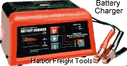 battery charger. For a battery to power the ignition, a
small, lightweight and rechargeable
12 volt sealed lead acid (SLA) battery with a minimum 4Ah
(Amp Hour) rating or a small
motorcycle battery can be used.
battery charger. For a battery to power the ignition, a
small, lightweight and rechargeable
12 volt sealed lead acid (SLA) battery with a minimum 4Ah
(Amp Hour) rating or a small
motorcycle battery can be used.
FYI - Kohler's Breakerless Ignition and Tecumseh's Solid State Ignition (SSI) systems use a key switch that's also made for a self-energizing magneto or magneto-type solid state ignition system. Unlike the OFF-ON-START key switch for a battery-powered ignition system, just like the magneto or solid state ignition systems, with the Breakerless Ignition is self-energizing, and to kill the engine, the key switch grounds out or shorts the [low voltage] circuit between the energizing coil and ignition module. But the battery type OFF-ON-START key switch opens the circuit to kill the engine. So with the battery-powered points and condenser ignition system (along with a 12 volt coil), you will need to use a battery type OFF-ON-START key switch, or an OFF-ON toggle switch or an OFF-ON rotary key switch to power the ignition with a momentary push button starter switch to crank the engine. If swapping out the OEM Breakerless Ignition, magneto or solid state (grounding type) OFF-ON-START ignition key switch for a battery type OFF-ON-START key switch, the wire connectors in the wiring connector will need to be rearranged to match the terminals on the battery type key switch to crank the engine, power the ignition and electrical accessories, and recharge the battery. I've performed this before on some of my customer's ordinary garden tractors and garden pulling tractors, and it works great. Click/tap here for battery-powered ignition wiring diagrams. |
|
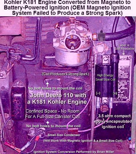 Several years ago,
an out of town customer brought his John Deere model 110 to our shop for
repairs. This tractor has a Kohler engine model K181 with self-energizing
magneto ignition and a 10 amp alternator charging system. (The ignition coil
and charging coils are mounted on the same armature/stator frame under the
flywheel.) My customer told me that he had another reputable small engine
repair shop in his hometown install a new spark plug, points, condenser and
an entirely new armature/stator assembly, but they could not get the engine
to rev up. Several years ago,
an out of town customer brought his John Deere model 110 to our shop for
repairs. This tractor has a Kohler engine model K181 with self-energizing
magneto ignition and a 10 amp alternator charging system. (The ignition coil
and charging coils are mounted on the same armature/stator frame under the
flywheel.) My customer told me that he had another reputable small engine
repair shop in his hometown install a new spark plug, points, condenser and
an entirely new armature/stator assembly, but they could not get the engine
to rev up.
Anyway, I put the tractor on the sturdy
platform table that I
built to make it easier to work on. The engine would start right up and idle
well, but failed to rev up. It would just die out when throttled up. So I
cleaned and inspected the entire carburetor, including clearing out anything
that may have been lodged in the main jet; tried a new Autolite 295 copper
core spark plug gapped at .030"; cleaned and reset the points gap; tried
another new condenser; So after some thoughtful consideration, I came to the conclusion that the OEM Kohler part # 237876 self-energizing magneto ignition/charging system armature/stator assembly is obviously a notorious, bad design. Although this system is still available new from Kohler, Kohler discontinued installing this on certain engines only after a short time. (Apparently, for an obvious reason.)
If you have a similar ignition problem like this and if you're interested, I offer all the parts, including a new 12 volt 3.5 ohm high energy compact epoxy-encapsulated armature ignition coil kit, that can be used to convert the self-energizing magneto ignition to battery-powered ignition for your tractor. See the complete ignition conversion kit(s) below. I can also convert your tractor from a faulty self-energizing magneto ignition to the more reliable battery-powered ignition if you don't mind bringing your tractor to my shop. - A-1 Miller's Please contact A-1 Miller's if you're interested in purchasing any of the products listed in this website. If you need a part or parts that's not listed in this website, please contact A-1 Miller's and we'll see if we can get it at a reasonable price. | [Top of Page]
Convert virtually any single cylinder, air-cooled cast iron or various aluminum block small gas engine, such as Kohler, Tecumseh, Briggs & Stratton, Clinton, etc., with a failed self-energizing magneto ignition system to the battery-powered ignition system. NOTE: Must use a universal automotive off/ignition/start key switch, or a push button switch to crank the engine with an OFF-ON toggle switch or OFF-ON rotary key switch to power this ignition. Reuse same type of spark plug and existing ignition points (if in good condition), but set the point gap at .020" or set ignition timing at 20º BTDC. See ignition kits and wiring diagram below Ê.
NOTE: A small, fully charged 12 volt battery is required for this ignition
system. A
High Quality Ignition Kit to Convert from Kohler Magneto Ignition to the More Reliable Battery-Powered Ignition System for an Unconfined Engine Compartment with Unlimited Space to mount a full size canister coil. Designed for Kohler engine models K90/K91, K141, K161/K160, KV161, L160/L161, L181, K181, K241, K301, K321, K330/K331 and K341.
When ordering, please indicate make and model of engine. Ignition parts kit include:
NOTE: A small, fully charged 12 volt battery is required for this ignition
system. A
|
|
| New points, condensers/capacitors, coils and spark plugs for other makes and models of engines are also available. Please call or email A-1 Miller's for your needs. Please contact A-1 Miller's if you're interested in any of the above È parts. | |
How to Accurately Set the Ignition Timing on Virtually Any Gas Engine with Points and Condenser Ignition - [Top of Page]
First of all, on a single cylinder cast iron block Kohler engine, anything less than a .020" (which is 20º BTDC) points gap is retarding the ignition timing less than its normal setting, and more than .020" is advancing the timing beyond its normal setting. But sometimes the points lobe on the cam will wear, and the ignition timing can't be fully advanced with a .020" points gap for the 20º BTDC setting. On a Kohler (and virtually any engine without an ignition distributor), widening or narrowing of the points gap is how the ignition timing is adjusted. Widening the gap advances the timing and narrowing it retards the timing, and rotating the distributor does the same. On a Kohler engine, adjust the ignition points by first positioning the piston at TDC on the compression stroke. This is when both valves are fully closed. Then slightly loosen the adjustment screw on the ignition points and place the flat screwdriver in the slot on the points bracket and points lever to widen and narrow the point gap. Then use a [preferably clean] .020" feeler gauge to set the gap. If the screw that fastens the ignition points to the bracket is difficult to get at with a screwdriver on the equipment, then install a socket (Allen) Head screw and use an angled hex key (Allen) wrench to loosen and tighten the screw that secures the ignition points in place. Delayed or hesitant revving up of the engine indicates either low compression, or the ignition timing is retarded and not set at 20º BTDC. FYI - A feeler gauge is a must-have tool for checking point gaps, valve clearances, piston ring gaps, camshaft and crankshaft end-play and other critical measurements.
To precisely set the ignition timing on the K-series single cylinder engines, if there are no T or S marks on the flywheel, bring the piston at TDC on the compression stroke, and gently rock the flywheel by hand side to side. You will feel "free play". Midway of the free play is true TDC, or 0° TDC. Now with the flywheel at the same position, place a T on the left side of the flywheel in exact alignment with the raised boss on the bearing plate, and place an S at 1-5/8" above the T. The S is 20° BTDC. This is where the timing needs to be set. Now rotate the flywheel until the S is aligned with the raised boss. Connect a multimeter set on the ohms resistance or a battery powered test light between the points wire and engine ground to indicate when the points are open and closed. Rotate the flywheel slightly when the points open exactly when the S is aligned with the raised boss. Now the timing is precisely set at 20° BTDC.
TIP: To prevent small Phillips- or slotted-head screws from falling out of the screwdriver tip when installing in a hard to reach place, for ordinary steel screws, temporarily magnetize the screwdriver by rubbing a magnet several times along the length of the shank, and for stainless steel screws, apply a dab of automotive grease in the head of the screw.
IMPORTANT! Running an engine with insufficient or severely retarded ignition timing will cause accelerated internal wear and lead to oil burning over time. When the timing is retarded (spark occurs too late before the piston reaches top dead center), the fuel mixture does not have time to burn completely inside the combustion chamber, and some it exits out the exhaust. This results in several cascading issues:
On the other hand, when the timing is too advanced (beyond factory recommendation), the spark plug(s) fires too early, causing the air-fuel mixture to ignite and expand while the piston(s) is/are still moving upward. While moderate advancement of the timing increases power and efficiency, with low octane gas, going too far reduces performance, causes dangerous engine knocking (detonation) and pinging, and can severely damage the engine.
Most spark ignited gas engines with a
fixed advanced timing can't start under full compression AND with fixed advanced
ignition timing. With fixed advanced timing, one or the other must be
"suppressed" in order for the engine to crank over without "kicking back"
to start. Either it needs to have an automatic compression release to relieve
about half the compression, then full compression will return upon start
up. Or the timing needs to be positioned at TDC, then with an automatic advance
feature, it will fully advance upon start up. On engines with a camshaft
having an automatic compression release (ACR), the ignition timing cannot
be advanced more than approximately 25º BTDC. If it is, the spark will
occur when the exhaust valve opens slightly (to relieve the compression),
and the engine may not start or be hard to start. It may pop out the carburetor
instead. If the timing needs to be set more than 25º BTDC (for methanol
fuel), the ACR will need to be removed from the camshaft, and to make the
engine easier to crank over and start under full compression, a high torque
gear starter, heavy [steel] flywheel, along with separate starter and ignition
switches will need to be used to prevent "kickback" when attempting to start
the engine. "Kickback" occurs when the crankshaft/flywheel
suddenly and quickly momentarily rotates in the opposite direction, which
is could bend or break the starter armature shaft or break the aluminum starter
housing. To start any engine with advanced timing and under full compression,
two separate switches will need to be used. A push button switch to crank
the engine, and an OFF-ON toggle switch or OFF-ON rotary key switch to power
the ignition. To make this work, first crank the engine over, and while it's
cranking over, choke the carburetor (or install
A-1 Miller's remote fuel primer
system), then turn on the ignition switch to "put the spark to it." The
engine should start easily every time. This method works because the continuing
centrifugal spinning force of the flywheel prevents the engine from "kicking
back" when power is being supplied to the ignition.
A way to start an engine with an electric starter that has full compression and no automatic compression release AND fixed or "set in the fully advanced position" full advanced timing is to use two separate switches. One to crank the engine, and one for the ignition to "put the spark to it " so it will start without kickback.
FYI - I've been to many car races, and truck and tractor pulls through the years, and I've noticed that when most drivers start their engine, they use a push button switch to crank it over first , then turn on the ignition switch, and the engine would start every time with no hesitation. I found the reason they start their engine in this order is because the ignition timing is "fixed" in the fully advanced position with no retard. Starting the engine this way prevents "kickback" (when the flywheel/crankshaft rebounds sharply each time when attempting to start the engine), which prevents breaking the aluminum starter motor housing. This is why Tecumseh engines with my custom ignition system listed above should be started. Many high-performance automotive engine builders often weld the mechanical advance weights in place and they install a solid plate in place of the vacuum advance canister, so the ignition timing is in a "fixed" position, ensuring the total timing remains the same rather than automatically advancing with RPM. This technique is common in high-performance engines to prevent detonation and provide a consistent ignition curve.
The point gap on virtually all 4-cycle small gas engines, rather if it has one or two cylinders, is set using a .020" feeler gauge with the piston positioned at TDC on the compression stroke. This is when the valves (#1 cylinder for a opposed twin cylinder) are fully closed. This sets the ignition timing approximately at 20º BTDC (Kohler engines), and is the most easiest and simplest way to basically set the timing. A better way is to statically (engine not running) set the timing. But the most accurate way is use a strobe timing light to dynamically set the timing. The timing light connects to the battery and spark plug wire. FYI - A feeler gauge set is a must-have tool for checking point gaps, valve clearances, piston ring gaps, camshaft and crankshaft end-play and other critical measurements.
Static ignition timing is when it is checked or set with the engine not running using a continuity tester (self-powered test light, analog multimeter or digital multimeter, switch either on the ohm (d) setting, and make sure the battery in either multimeter is fully charged. And dynamic ignition timing is when it is checked or set with the engine running using a strobe timing light. To accurately set the ignition timing on an engine with points, condenser/capacitor and a stock flywheel, make sure the battery in either multimeter is fully charged. The points contacts will act as a momentary switch to turn the test light off and on or make resistance in either meter. To make this happen...
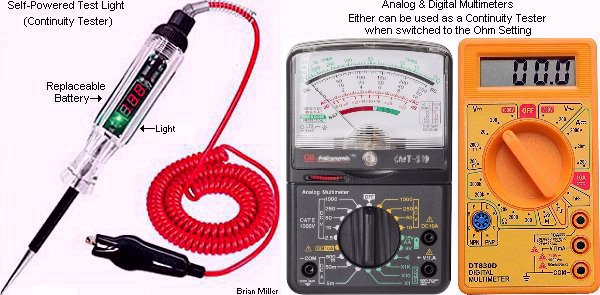 Connect one lead of the
continuity tester
(self-powered test light,
analog multimeter or
digital multimeter, switch either on the ohm
setting) to the ignition points terminal screw
or the points wire (disconnect it from the coil first) and the other lead
to engine/chassis ground so the points will serve as a switch to illuminate
the light or activate the meter.
ignition points file (professional use) or
metal fingernail file (use in a pinch) to remove any
oxidation/debris between the contacts, then drag a piece of [preferably clean]
lint-free paper through the contacts to remove any left-over residue, and
use
brake parts cleaner,
electrical/electronic contact cleaner,
cleaning solvent or
paint thinner (these leave no oily residue) and then use
150± psi compressed air with an
air blow gun nozzle to clean any remaining debris and metal
filings from the contacts. This will guarantee 100% connection with the
points.
Connect one lead of the
continuity tester
(self-powered test light,
analog multimeter or
digital multimeter, switch either on the ohm
setting) to the ignition points terminal screw
or the points wire (disconnect it from the coil first) and the other lead
to engine/chassis ground so the points will serve as a switch to illuminate
the light or activate the meter.
ignition points file (professional use) or
metal fingernail file (use in a pinch) to remove any
oxidation/debris between the contacts, then drag a piece of [preferably clean]
lint-free paper through the contacts to remove any left-over residue, and
use
brake parts cleaner,
electrical/electronic contact cleaner,
cleaning solvent or
paint thinner (these leave no oily residue) and then use
150± psi compressed air with an
air blow gun nozzle to clean any remaining debris and metal
filings from the contacts. This will guarantee 100% connection with the
points.
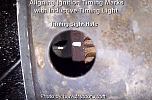 On Kohler flywheels, there should
be a T and S stamped on the outer edge
of the flywheel with a line stamped underneath each letter. Clean the area
off, and use a
Sharpie metallic silver permanent ink marker,
yellow or white paint marker, or a white or yellow paint
mark with a small artist brush, to place a brightly colored mark on the
S mark [punched line] so it can be easily seen with the
naked eye and with a strobe timing light. The
timing light connects to the battery and spark plug wire.
T stands for TDC, which is 0º TDC. This is where the
ignition timing sets if the engine is equipped with an older two-piece camshaft
with a rotating automatic timing advance mechanism (ignition points lobe).
And S stands for Spark Advance, which is 20º BTDC.
This is where the timing sets if the engine is equipped with a one-piece
camshaft that came with an automatic compression release (ACR) mechanism.
On the Kohler K-series 10-16hp cast iron block engines, there are three different
places where the timing sight hole is located.
On Kohler flywheels, there should
be a T and S stamped on the outer edge
of the flywheel with a line stamped underneath each letter. Clean the area
off, and use a
Sharpie metallic silver permanent ink marker,
yellow or white paint marker, or a white or yellow paint
mark with a small artist brush, to place a brightly colored mark on the
S mark [punched line] so it can be easily seen with the
naked eye and with a strobe timing light. The
timing light connects to the battery and spark plug wire.
T stands for TDC, which is 0º TDC. This is where the
ignition timing sets if the engine is equipped with an older two-piece camshaft
with a rotating automatic timing advance mechanism (ignition points lobe).
And S stands for Spark Advance, which is 20º BTDC.
This is where the timing sets if the engine is equipped with a one-piece
camshaft that came with an automatic compression release (ACR) mechanism.
On the Kohler K-series 10-16hp cast iron block engines, there are three different
places where the timing sight hole is located.
 It's on either side of the flywheel
shroud, or on the back of the bearing plate on the right side, such as with
engines having a starter/generator, when facing the flywheel. You will need
to look under the starter bracket to see the sight hole. It may have a factory
installed
zinc hole plug in it. If the timing sight hole is on either
side of the flywheel shroud, then the timing marks are located on the outer
edge of the flywheel. But if the timing sight hole is on the backside of
the bearing plate, then the timing marks are located on the backside edge
of the flywheel. If the marks can't be seen, then the flywheel will need
to be cleaned off and depending on type of camshaft that's in the engine,
the brightly colored mark with a
Sharpie metallic silver permanent ink marker,
yellow or white paint marker, or a white or yellow paint
mark with a small artist brush, needs to placed on the stamped line under
the T mark (0º TDC) for the older two-piece camshaft
with the automatic timing advance, or on the stamped line under the
S mark (20º BTDC) for the newer one piece camshaft
with the automatic compression release (ACR). If there is a
T mark, but no visible S mark on the
flywheel, for flywheels with the timing mark on the outer edge on the left
side, the S is located exactly 1-5/8" (1.625") above
the T mark. And for flywheels with the timing mark on the
outer or backside edge of the flywheel on the right side, the
S is located exactly 1-5/8" (1.625") below the
T mark. If there's no timing marks at all on the flywheel,
such as with certain billet steel flywheels, the flywheel will need to be
degreed-in with a degree wheel, dial indicator and
piston stop to create new timing marks. Some billet steel flywheels have
the timing marks inscribed on the backside edge of the flywheel, and must
be transferred to the outer edge for visibility when using a factory flywheel
shroud.
It's on either side of the flywheel
shroud, or on the back of the bearing plate on the right side, such as with
engines having a starter/generator, when facing the flywheel. You will need
to look under the starter bracket to see the sight hole. It may have a factory
installed
zinc hole plug in it. If the timing sight hole is on either
side of the flywheel shroud, then the timing marks are located on the outer
edge of the flywheel. But if the timing sight hole is on the backside of
the bearing plate, then the timing marks are located on the backside edge
of the flywheel. If the marks can't be seen, then the flywheel will need
to be cleaned off and depending on type of camshaft that's in the engine,
the brightly colored mark with a
Sharpie metallic silver permanent ink marker,
yellow or white paint marker, or a white or yellow paint
mark with a small artist brush, needs to placed on the stamped line under
the T mark (0º TDC) for the older two-piece camshaft
with the automatic timing advance, or on the stamped line under the
S mark (20º BTDC) for the newer one piece camshaft
with the automatic compression release (ACR). If there is a
T mark, but no visible S mark on the
flywheel, for flywheels with the timing mark on the outer edge on the left
side, the S is located exactly 1-5/8" (1.625") above
the T mark. And for flywheels with the timing mark on the
outer or backside edge of the flywheel on the right side, the
S is located exactly 1-5/8" (1.625") below the
T mark. If there's no timing marks at all on the flywheel,
such as with certain billet steel flywheels, the flywheel will need to be
degreed-in with a degree wheel, dial indicator and
piston stop to create new timing marks. Some billet steel flywheels have
the timing marks inscribed on the backside edge of the flywheel, and must
be transferred to the outer edge for visibility when using a factory flywheel
shroud.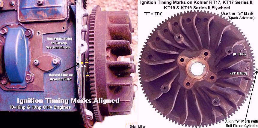 Engines can't start under full compression
and with advanced ignition timing. One or the other must be "suppressed"
in order for the engine to crank over without "kicking back" to start. Either
it needs to have an automatic compression release to relieve about half the
compression, then the compression will return at open upon start up, or the
timing needs to be positioned at TDC, then it can automatically advance upon
start up. On engines with a camshaft having an automatic compression release
(ACR), the ignition timing cannot be advanced more than approximately 25º
BTDC. If it is, the spark will occur when the exhaust valve opens slightly
(to relieve the compression), and the engine may not start or be hard to
start. It may pop out the carburetor instead. If the timing needs to be set
more than 25º BTDC (for methanol fuel), the ACR will need to be removed
from the camshaft, and to make the engine easier to crank over and start
under full compression, a high torque gear starter, heavy [steel] flywheel,
along with separate starter and ignition switches will need to be used to
prevent "kickback" when attempting to start the engine.
With advanced timing, and no mechanical timing retard
or no automatic compression release, chances are this will cause the engine
to "kickback" when attempting to start it. "kickback" occurs when the
crankshaft/flywheel suddenly and quickly momentarily rotates in the opposite
direction, which is could bend or break the starter armature shaft or break
the aluminum starter housing. To start any engine with advanced timing and
under full compression, two separate switches will need to be used. A push
button switch to crank the engine, and an OFF-ON toggle switch or OFF-ON
rotary key switch to power the ignition. To make this work, first crank the
engine over, and while it's cranking over, choke the carburetor (or install
A-1 Miller's remote fuel primer
system), then turn on the ignition switch to "put the spark to it." The
engine should start easily every time. This method works because the continuing
spinning centrifugal force of the flywheel prevents the engine from "kicking
back" when power is being supplied to the ignition.
Engines can't start under full compression
and with advanced ignition timing. One or the other must be "suppressed"
in order for the engine to crank over without "kicking back" to start. Either
it needs to have an automatic compression release to relieve about half the
compression, then the compression will return at open upon start up, or the
timing needs to be positioned at TDC, then it can automatically advance upon
start up. On engines with a camshaft having an automatic compression release
(ACR), the ignition timing cannot be advanced more than approximately 25º
BTDC. If it is, the spark will occur when the exhaust valve opens slightly
(to relieve the compression), and the engine may not start or be hard to
start. It may pop out the carburetor instead. If the timing needs to be set
more than 25º BTDC (for methanol fuel), the ACR will need to be removed
from the camshaft, and to make the engine easier to crank over and start
under full compression, a high torque gear starter, heavy [steel] flywheel,
along with separate starter and ignition switches will need to be used to
prevent "kickback" when attempting to start the engine.
With advanced timing, and no mechanical timing retard
or no automatic compression release, chances are this will cause the engine
to "kickback" when attempting to start it. "kickback" occurs when the
crankshaft/flywheel suddenly and quickly momentarily rotates in the opposite
direction, which is could bend or break the starter armature shaft or break
the aluminum starter housing. To start any engine with advanced timing and
under full compression, two separate switches will need to be used. A push
button switch to crank the engine, and an OFF-ON toggle switch or OFF-ON
rotary key switch to power the ignition. To make this work, first crank the
engine over, and while it's cranking over, choke the carburetor (or install
A-1 Miller's remote fuel primer
system), then turn on the ignition switch to "put the spark to it." The
engine should start easily every time. This method works because the continuing
spinning centrifugal force of the flywheel prevents the engine from "kicking
back" when power is being supplied to the ignition.
The most accurate way to set the ignition timing is dynamically. This is with the engine running and a strobe timing light. The timing light connects to the battery and spark plug wire. Connect the timing light (if it has an adjustable degree wheel, set it at 0º), then start the engine. With the engine running at idle speed, shine the timing light through the sight hole in the flywheel shroud to see the painted "S" mark on the flywheel and the raised line on the bearing plate. When the marks are perfectly aligned, this is when the timing is set exactly at 20º BTDC. This cannot be done on an aftermarket steel flywheel or [starter] pulley on the PTO end of the crankshaft with no timing marks.
The ignition timing greatly depends on where the spark plug is located in the combustion chamber. Most plugs are centered in the combustion chamber. But if it's closer to the exhaust valve, the timing must be advanced slightly more. Location of the spark plug in the combustion chamber and proper ignition timing are two things that's very important in engine performance. Actually, it's best to set the timing with some test pulls or with the engine connected to an engine dynamometer.
NOTE: The above method is sufficiently accurate and useful in building a fresh engine and not having to mess with adjusting the ignition points just to get the engine started for the first time. However, after getting the engine started, it's always a good thing to use either a strobe timing light to check to see if the timing is set exactly where it's supposed to be. The timing light connects to the battery and spark plug wire. This is called setting the timing dynamically. Use a timing light when the timing marks on both the bearing plate and flywheel are perfectly aligned. The ignition timing setting for Kohler engines burning GAS is 20-22º BTDC. NEVER run over-advanced timing (beyond the 22º setting) with gas just to try to get "more power" out of an engine! All that'll do is seriously overheat the engine and ruin parts. [Return to previous paragraph, section or website]
Setting the Ignition Timing with a Strobe Timing Light - [Return to previous paragraph, section or website]
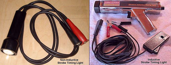 There are 3 types of strobe
timing lights, in-line/neon, analog, and digital.
There are 3 types of strobe
timing lights, in-line/neon, analog, and digital.
In-Line/Neon Timing Light. This very old, vintage, self-powered timing lights relied solely on the electrical energy from the ignition circuit to flash.
Analog vs Digital Timing Lights - (Added 6/5/26)
An analog timing light uses a mechanical dial to set advance and a simple xenon strobe to illuminate timing marks, while a digital timing light uses an LCD screen, pushbuttons, and microprocessor-controlled circuitry to display RPM, advance, and voltage readouts. To use an inductive analog timing light or digital timing light, the engine can be running while connecting the clamps on the battery posts in their respective order, then connect the inductive pickup on the #1 spark plug wire. Choosing between the two depends on your budget and how often you tune your engine.
Which One Should You Choose?
Engines can't start under full compression and with advanced ignition timing. One or the other must be "suppressed" in order for the engine to crank over without "kicking back" to start. Either it needs to have an automatic compression release to relieve about half the compression, then the compression will return at open upon start up, or the timing needs to be positioned at TDC, then it can automatically advance upon start up. If an engine has an automatic compression release on the camshaft and the valve clearance is set right (at least for the exhaust valve), chances are the engine will not "kickback" when attempting to start the engine. "kickback" occurs when the crankshaft/flywheel suddenly and violently rebounds or rotates in the opposite direction, which is could bend or break the starter armature shaft or break the aluminum starter housing. To start any engine with advanced timing and under full compression, two separate switches will need to be used. A push button switch to crank the engine, and an OFF-ON toggle switch or OFF-ON rotary key switch to power the ignition. To make this work, first crank the engine over, and while it's cranking over, choke the carburetor (or install A-1 Miller's remote fuel primer system), then turn on the ignition switch to "put the spark to it." The engine should start easily every time. This method works because the continuing spinning centrifugal force of the flywheel prevents the engine from "kicking back" when power is being supplied to the ignition.
The ignition on Kohler engines aren't like the ignition on most automotive engines. You don't dwell-in the ignition points on a Kohler engine. Instead, you set the point gap at .020" as the initial setting just to get the engine running. Then the ignition timing is set by widening or narrowing the ignition points gap until the timing is at 20º BTDC by observing the alignment timing marks on the flywheel.
NOTE: If the ignition timing is set right and the engine kicks back when trying to start, sometimes, but not always, the compression release isn't relieving enough compression from the combustion chamber. When this happens, try setting the valve clearances to specs and see if that makes a difference. If the timing is retarded at all times with no automatic advance just to reduce the possibility of "kickback" upon startup, then it will run sluggish and not produce enough power. [Return to previous paragraph, section or website]
Another simple way to set the ignition timing is to use a dial indicator to measure the distance of the piston from the top of the block. On the K241 (10hp) Kohler engines, the ignition points just begin to open when the piston is located exactly at .125" BTDC. And on the K301 (12hp), K321 (14hp), K341 (16hp) flathead engines and K361 (18hp OHV) engines, the ignition points just begin to open when the piston is located exactly at .100" BTDC. Distances shown is when the S mark on the flywheel is aligned with the mark on the bearing plate. Take into consideration if the piston doesn't come flush with the top of the block, or if it protrudes out of the cylinder. EXCEPTION: When setting the ignition timing on an older Kohler engine with the old style two-piece camshaft, set the ignition points so they just begin to open with the piston positioned on the compression stroke at 0º TDC (T mark on the flywheel). As soon as the engine starts, the ignition points lobe rotates on the cam pin and flyweights on the cam gear automatically advances the timing to 20º BTDC. Don't set the initial timing at 20º BTDC (S mark) with the old style two-piece camshaft. Due to the absence of an automatic compression release (these engines start under full compression), setting it at 20º BTDC will advance the timing too much and cause the engine to "kickback" when attempting to start the engine. "Kickback" occurs when the crankshaft/flywheel suddenly and quickly momentarily rotates in the opposite direction, which is could bend or break the starter armature shaft or break the aluminum starter housing. To start any engine with advanced timing and under full compression, two separate switches will need to be used. A push button switch to crank the engine, and an OFF-ON toggle switch or OFF-ON rotary key switch to power the ignition. To make this work, first crank the engine over, and while it's cranking over, choke the carburetor (or install A-1 Miller's remote fuel primer system), then flip the ignition switch to "put the spark to it." The engine should start easily every time. This method works because the continuing spinning centrifugal force of the flywheel prevents the engine from "kicking back" when power is being supplied to the ignition.
How To Read A Dial Indicator -
 Each mark on
the face of a dial indicator represents one thousand of an inch (.001")
graduations. The marks with a number (10, 20, 30, etc.) represents every
ten thousands (.010"). Depending on the size of the engine, for a reading
of .050" or .070" BTDC, first, run the piston up at true TDC, then set the
dial indicator at the .050" or .070" mark. Then, slowly rotate the crankshaft
in opposite of normal engine rotation until the needle reads 0 degrees BTDC.
The needle will move in the counterclockwise
Each mark on
the face of a dial indicator represents one thousand of an inch (.001")
graduations. The marks with a number (10, 20, 30, etc.) represents every
ten thousands (.010"). Depending on the size of the engine, for a reading
of .050" or .070" BTDC, first, run the piston up at true TDC, then set the
dial indicator at the .050" or .070" mark. Then, slowly rotate the crankshaft
in opposite of normal engine rotation until the needle reads 0 degrees BTDC.
The needle will move in the counterclockwise
 (left-hand or reverse rotation of an analog
clock) direction (back to the 0 degree mark) as the piston moves downward
in the cylinder.
(left-hand or reverse rotation of an analog
clock) direction (back to the 0 degree mark) as the piston moves downward
in the cylinder.
Where
is the Timing Sight Hole in the Flywheel Shroud?
On the small [8"] flywheel without the starter ring gear and with the starter/generator, the timing sight hole is on the right when facing the front of the flywheel, or on the same side as the starter/generator. But on the large [9-1/2"] flywheel with the starter ring gear and gear starter, the timing sight hole is on the left when facing the front of the flywheel, or on the same side of the carburetor.
To set the ignition timing on the 7hp and 8hp Kohler engines, there's a sight hole in the backside of the bearing plate on the starter/generator side, just behind the flywheel. It has a metal hole cover plug in it. Remove the plug, then slowly rotate the flywheel by hand until you see the S mark. Place a white paint mark on the line. Now connect a strobe timing light, start the engine and note if the mark appears midway in the sight hole. If not, adjust the ignition points until the mark is centered in the hole. This is how you set the ignition timing with a timing light. The timing light connects to the battery and spark plug wire.
It is recommended that a steel flywheel be degreed in on an engine to locate true TDC. Mark the flywheel every 5 degrees out up to 35 degrees BTDC. NOTE: With a steel cam and ground-on point lobe, do not correlate ignition points gap with engine timing – there is a range from approximately 10 degrees BTDC to 40 degrees BTDC! Use a continuity tester to set ignition points to the desired ignition timing by setting the points gap at a specific width.
The initial ignition timing must be properly set and be able to automatically advance (if this feature is on the engine) when the engine starts for the engine to produce full power. The initial timing is set according to when the piston reaches its Before Top Dead Center (BTDC) position in the cylinder on the compression stroke. When measuring the piston distance, take in consideration if a piston protrudes out of the cylinder or if it doesn't come flush with the top of the block. And don't trust strange markings on the flywheel.
Simple Ways to Find Top Dead Center (TDC) of the Piston on the Compression Stroke -
Top Dead Center (TDC) of the compression stroke is when the piston is at its furthest top of the cylinder and both valves are fully closed. If the piston is at TDC and each valve slightly opens then closes when the flywheel or crankshaft is rotated by hand one or the other, the engine is on the exhaust stroke and the crankshaft needs to be rotated 180º to be on the compression stroke. Another way is when the keyways on each end of the crankshaft are positioned straight up with the cylinder, this is when the piston is at 0º TDC. One way to find TDC is with a straight edge tool placed across and centered on the keyway of the crankshaft PTO end. When it's perpendicular with the engine, this is when the piston is at TDC. Another way to find TDC is to "feel" when the piston is at TDC by rocking the flywheel back and forth slowly and gently by hand. Vise Grips lightly clamped on the crankshaft PTO end can be used instead. You will feel the slight "free play" of the oil clearance in the main bearings and connecting rod-to-crank journal when the piston/crankshaft is moved just before and after TDC. When the piston is positioned halfway between the "free play", it is exactly at TDC.
How to Set the Ignition Timing on an Engine that has a Flywheel with no Timing Marks | Use the Correct Tools Below to Precisely Set the Ignition Timing | Find TRUE Top Dead Center (0º TDC) on an engine with an OEM, billet steel flywheel or billet starter pulley with no timing marks to accurately set the ignition (or cam) timing. FYI - These tools are also used to degree in a high-performance camshaft in an automotive or competition pulling Kohler engine with an adjustable cam gear.
The Degree Wheel is a round disc (usually made of aluminum) with the facing edge marked off in degrees, similar to the markings on a protractor. It's actually two 180º protractors put together to form a 360º circle. When used in conjunction with a dial indicator, it's installed on the crankshaft during the engine build to degree the cam in and check for correct valve timing events. It can also be used to check for accurate ignition timing. When in use, a degree wheel is fastened to the front of the crankshaft (automotive engines) or flywheel end (small engines). If it's fastened to the PTO end, it will need to face the engine block and be read from that position. |
Dial Indicator and Magnetic Base A Dial Indicator is necessary to check for correct valve timing to tell precisely when a valve starts to open and the moment it closes. This opening and closing is very critical for high-performance engines and cannot be done by feel or by sight. A dial indicator can also be used to set accurate ignition timing in relation to piston travel. Each mark on the face of a dial indicator represents one thousandth of an inch (.001") graduations. The marks with a number (10, 20, 30, etc.) represents every ten thousandths of an inch (.010", .020", .030", etc.). A dial indicator always mounts on top of the engine block with a sturdy bolt-on bracket or a magnetic base. Dial indicators are very precision and delicate instruments. Care must be used in handling one. |
Piston Stop Tool
The plug-type piston stop can be made from an old spark plug or one can be purchased in manufactured material. The flat bar piston stop can also be purchased in manufactured material or it can be made from scratch. The flat bar type piston stop can be used on a flathead engine or an Over Head Valve (OHV) engine. To make the flat bar piston stop, it can be made of minimum 1/4" thick x 1" wide flat steel or aluminum, drilled with a couple of holes so that it can be fastened to the top of the block with a couple of short bolts directly over the piston. A 1/4" bolt with a jam nut is threaded in the bar to serve as the bump-stop. Up and down (horizontal shaft engines) or in and out (vertical shaft engines) adjustment of the bolt is used to "stop" the piston. If a piston pops out of the cylinder at TDC, flat washers will need to be used between the bar and block so it will clear the piston at TDC.
|
|
With an aftermarket steel flywheel or a stock flywheel with no timing marks, the most accurate way to set the ignition timing [on virtually any engine] is performed by measuring the distance of the piston before it reaches top dead center with a dial indicator in conjunction with a degree wheel fastened to the crankshaft flywheel end. To learn more, read below...
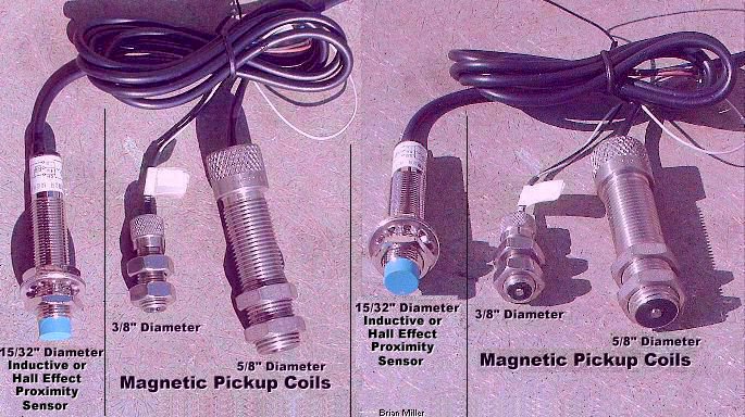 Rotate the crankshaft by hand
in its normal direction until the degree wheel is where you want the timing
to be set at (20º), then adjust the ignition points so they just
begin to open. The
self-powered test light should've gone off or flickered
by now. If not, set the ignition points so they just start to open
and the light flickers. Once the degree wheel is in the proper position,
the breaker points should just begin to open. Or, when using crank-trigger
and flywheel-triggered ignition, check or set the initial timing by positioning
the center of the magnetic pickup coil or 3-wire inductive
proximity sensor with the center of the detectable target, rather if
it's a small magnet, screw, pin, projection (hump) or large bolt head on
the edge of a flywheel or on a rotating disc. It is at this moment when spark
occurs. And it's at this point that the ignition timing is set correctly.
Mark the flywheel or front pulley where the timing marks are on the degree
wheel for setting the timing with a strobe timing
light in the future. The timing light connects to the battery and spark
plug wire.
Rotate the crankshaft by hand
in its normal direction until the degree wheel is where you want the timing
to be set at (20º), then adjust the ignition points so they just
begin to open. The
self-powered test light should've gone off or flickered
by now. If not, set the ignition points so they just start to open
and the light flickers. Once the degree wheel is in the proper position,
the breaker points should just begin to open. Or, when using crank-trigger
and flywheel-triggered ignition, check or set the initial timing by positioning
the center of the magnetic pickup coil or 3-wire inductive
proximity sensor with the center of the detectable target, rather if
it's a small magnet, screw, pin, projection (hump) or large bolt head on
the edge of a flywheel or on a rotating disc. It is at this moment when spark
occurs. And it's at this point that the ignition timing is set correctly.
Mark the flywheel or front pulley where the timing marks are on the degree
wheel for setting the timing with a strobe timing
light in the future. The timing light connects to the battery and spark
plug wire.
Magnetic pickup coils and proximity
sensors are very sensitive to mechanical damage (and electrical damage if
connected wrong). For magnetic pickup coils,
set the air gap/clearance from the detectable target (screw, pin or small
raised area on the rotating disc) at .010"-.060" with a brass
feeler gauge. And being 3-wire inductive
proximity sensors have a farther detection range, set the air gap/clearance
at .010"-.188". If the gap is wider than .188" (3/16") with either sensor,
the ignition system may not produce a spark or the engine could misfire at
higher RPM. To prevent the possibility of an out of time spark occurrence,
the detectable target needs to be a minimum of 3/16" higher than or above
the circumference surface of a steel or cast iron rotating disc or flywheel.
Direct metal contact with either sensor could damage them. When in
doubt if a sensor is mechanically damaged, look at the end of it with the
strong magnifying glass to see any damage. If it is damaged, it needs to
be replaced. A magnetic pickup coil can be tested with a digital
multimeter set on 200m DC, with the negative lead of the meter on the white
wire of the pickup coil and positive lead on the black wire, then pass a
small steel screw or bolt over the end of the magnetic pickup coil. If the
meter shows a reading, the pickup coil is in good condition.
How 3-Wire Proximity Sensors Work -
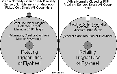
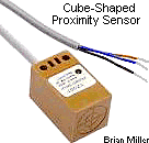 The 3-wire inductive and hall effect proximity sensors requires
external electrical power and function with three wires:
BROWN [power (+)],
BLUE [power (–)] and BLACK
[signal]. The body of metal case proximity sensors do not need to be grounded
to the battery negative (–) post. Proximity Sensors are like a small
generator and a switch in one unit. They come in two functions:
The 3-wire inductive and hall effect proximity sensors requires
external electrical power and function with three wires:
BROWN [power (+)],
BLUE [power (–)] and BLACK
[signal]. The body of metal case proximity sensors do not need to be grounded
to the battery negative (–) post. Proximity Sensors are like a small
generator and a switch in one unit. They come in two functions:
There's the NPN proximity sensor, which stands for Negative-Positive-Negative. "Negative" is when the sensor is turned off when it's NOT in close proximity of the target. This is when there's no activation or no spark occurs. And "Positive" is when the sensor is turned on or the electrical connection is made when the sensor is in close proximity of the target. This is when activation is made or the spark occurs. These type of sensors are known as Normally Open (NO). Normally Open is the same as when a mechanical switch is turned off or when no electrical connection is made, and no power is supplied to the electronic ignition control module/unit (ICU).
And there's the PNP proximity sensor, which stands for Positive-Negative-Positive. This works opposite than the sensor above. Again, "Positive" is when the sensor is turned on or the electrical connection is made when in close proximity of the target. This is when activation is made or the spark occurs. And "Negative" is when the sensor is turned off when it's NOT in close proximity of the target. This is when there's no activation or no spark occurs. These type of sensors are known as Normally Closed (NC). Normally Closed is the same as when a mechanical switch is turned on or when electrical connection is made, and power is supplied to the electronic ignition control module/unit (ICU). Go here to learn more: Proximity Sensor - Google Search | Proximity Sensor - YouTube | Testing NPN and PNP Proximity Sensors - YouTube.
A Normally Open proximity sensor produce electrical current to the ignition control module only when it comes in close proximity of a detectable ferrous metal (steel or cast iron) object, then the circuit is closed (LED sensor comes on). Proximity Sensors can only generate electricity when they come in close proximity of a small or narrow detectable iron-based ferrous metal object that a magnet can stick to. A special type of proximity sensor is required to work with non-magnetic metals, such as: aluminum, brass, copper, stainless steel, titanium, etc. Metal detectors, the kind that treasure hunters use, have the special type of proximity sensor.
Normally Open proximity sensors are used mainly for flywheel- or crank-trigger electronic ignition systems on gas engines. 3-wire inductive proximity sensors also work somewhat like metal detectors; if the metal comes close enough to the sensor, with a Normally Open proximity sensor, the alarm will sound. But a Normally Closed sensor works opposite.
How Inductive and Hall Effect Proximity Sensors Work -
The "inductive" proximity sensors can detect ferrous steel or iron-based metal objects or a magnet, being all magnets have iron in them. They will not work with non-magnetic metals, such as: aluminum, brass, stainless steel, titanium, etc. But the "hall effect" proximity sensors can only detect the presence of a magnetized metal object, such as the head of a steel screw fastened to a magnet on a disc or flywheel. Proximity sensors produce electrical current within and send it to the control module when external power is supplied to it (LED sensor goes off) except when it comes in close proximity of a detectable ferrous metal object, then the circuit is opened (LED sensor comes on). Certain proximity sensors have an LED (Light Emitting Diode) on the unit. If the proximity sensor is wired incorrectly, the LED will stay on and go off when activated. Proximity sensors are used mainly in places where security is needed. They can be used for exterior windows or doors in a secured building. When a window or door with a detectable ferrous metal object is moved away from the sensor, the circuit will be closed and an alarm will sound and/or lights will come on. Also, when a Normally Open proximity sensor is used with flywheel- or crank-trigger electronic ignition, the wider the gap in the rotating disc, the longer the duration of the spark, which makes for a more thorough burning of the fuel. It's almost impossible to tell the difference between a Normally Open and Normally Closed sensor just by looking at them because they appear to be identical. If a 3-wire inductive proximity sensor has no markings or indications to show that it's a Normally Open (N/O) and Normally Closed (N/C), a 100% sure way to determine the type, is read the label on the sensor (may need to use a strong magnifying glass), or test it with the wires connected in a circuit as shown in the drawings further down in this website. Ê Click here for more information: Proximity Sensor - YouTube.
How Magnetic and Non-Magnetic Pickup Coils Work -
A magnetic pickup coil works like a Normally Open proximity sensor. Magnetic pickup coils have two wires, are self-generating and require no external power. They can only generate electricity when they come in close proximity of a small or narrow detectable iron-based ferrous metal object that a magnet can stick to. They will not work with non-magnetic metals, such as: aluminum, brass, copper, stainless steel, titanium, etc. And a non-magnetic pickup coil also have two wires, are self-generating and require no external power. They can only generate electricity when it comes in close proximity of a small or narrow detectable magnet or magnetized metal object, such as the head of a ferrous metal steel screw fastening a magnet to the edge of a disc or flywheel. Click here for more information: Magnetic Pickup Coil - YouTube.
The hall effect sensor with a target magnet should be used with a rotating steel disc or cast iron flywheel that have an uneven outer surface with high spots. But when an inductive sensor is used with a non-magnetic steel target screw on a rotating steel disc or cast iron flywheel that have an uneven outer surface with high spots, this could trigger false spark(s) or send false signal(s) to the control module, which could produce an out-of-time spark or sequence. A hall effect sensor with a magnet will not allow this to happen.
Magnetic pickup coils and proximity
sensors are very sensitive to mechanical damage (and electrical damage if
connected wrong). For magnetic pickup coils,
set the air gap/clearance from the detectable target (screw, pin or small
raised area on the rotating disc) at .010"-.060" with a brass
feeler gauge. And being 3-wire inductive
proximity sensors have a farther detection range, set the air gap/clearance
at .010"-.188". If the gap is wider than .188" (3/16") with either sensor,
the ignition system may not produce a spark or the engine could misfire at
higher RPM. To prevent the possibility of an out of time spark occurrence,
the detectable target needs to be a minimum of 3/16" higher than or above
the circumference surface of a steel or cast iron rotating disc or flywheel.
Direct metal contact with either sensor could damage them. When in
doubt if a sensor is mechanically damaged, look at the end of it with the
strong magnifying glass to see any damage. If it is damaged, it needs to
be replaced. A magnetic pickup coil can be tested with a digital
multimeter set on 200m DC, with the negative lead of the meter on the white
wire of the pickup coil and positive lead on the black wire, then pass a
small steel screw or bolt over the end of the magnetic pickup coil. If the
meter shows a reading, the pickup coil is in good
condition.
How to Precisely Set the Ignition Timing
on Older Tecumseh Engines with points and condenser ignition -
[Top of Page]
|
|||||||||||||||||||||||||||||||||||||||||||||||||||||||||||||
How to Fix the Problem with a Severely Worn Ignition Points Lobe on a Kohler Camshaft or Breaker Cam - [Return to previous paragraph, section or website]
Sometimes the ignition points
lobe on the camshaft in a single cylinder Kohler engine or the breaker cam
(points lobe) in the governor assembly on Kohler engine models K482, K532
and K582 will become worn or have a groove wore in it so severe/deep that
the ignition timing can't be advanced to the factory setting of 20º
BTDC so the engine will produce full power. But there's a way to fix this,
and there's no need to purchase another camshaft or do welding on the points
lobe. Or install a threaded-on stainless steel nut on one end of the OEM
points pushrod for contact of the unworn sides of the points lobe, or convert
the engine to A-1 Miller's custom-made and reliable
flywheel-triggered 12 volt electronic
ignition. A stainless steel nut is very hard, yet slicker than a plain
steel nut, which will allow it to slide against the points lobe with less
friction, lessening wear to the unworn areas of the lobe. This will allow
the ignition timing to be fully advanced to 20º BTDC as if the lobe
isn't worn at all. The "stainless steel nut on the pushrod" can also be used
for an unworn points lobe for longer wear of the lobe. To fix the problem
with a severely worn points lobe...
 Acquire a stainless steel
10-24 UNC or 10-32 UNF (thread size) x 3/8" (wrench size) hex nut.
The minimum length of Kohler engine models
K90/K91, K241, K301, K321, K341, K361, K482, K532 and K582 ignition points
pushrod is 1.500" and maximum length is 1.550" (new). If you're using a stock
Kohler camshaft, then the OEM points pushrod should be long enough. And the
minimum length of Kohler engine models K141, K160/K161,
KV161,
L160/L161, L181 and
K181 ignition points pushrod is 1.260" and maximum length is 1.265" (new).
As long as the pushrod is anywhere between these two measurements, the ignition
points should adjust, open and close, and work just fine. But if either pushrod
is too short, the ignition points contacts won't open enough or at all, and
the rod will need to be replaced with a longer one. And if either pushrod
is too long, the ignition points' contacts won't touch and the rod will need
to be shortened. So measure accurately before (re)installing.
Personally, I've seen some poorly-designed custom-made aluminum mounting
brackets for Chevy points on competition pulling engines that have one or
both of the points mounting holes drilled and tapped too far away from the
engine block, making the OEM-length points pushrod too short, thus, making
adjustment of the points gap and activation of the points impossible. When
this happens, I drill and tap new points mounting hole(s) in the bracket
closer to the engine block.
Acquire a stainless steel
10-24 UNC or 10-32 UNF (thread size) x 3/8" (wrench size) hex nut.
The minimum length of Kohler engine models
K90/K91, K241, K301, K321, K341, K361, K482, K532 and K582 ignition points
pushrod is 1.500" and maximum length is 1.550" (new). If you're using a stock
Kohler camshaft, then the OEM points pushrod should be long enough. And the
minimum length of Kohler engine models K141, K160/K161,
KV161,
L160/L161, L181 and
K181 ignition points pushrod is 1.260" and maximum length is 1.265" (new).
As long as the pushrod is anywhere between these two measurements, the ignition
points should adjust, open and close, and work just fine. But if either pushrod
is too short, the ignition points contacts won't open enough or at all, and
the rod will need to be replaced with a longer one. And if either pushrod
is too long, the ignition points' contacts won't touch and the rod will need
to be shortened. So measure accurately before (re)installing.
Personally, I've seen some poorly-designed custom-made aluminum mounting
brackets for Chevy points on competition pulling engines that have one or
both of the points mounting holes drilled and tapped too far away from the
engine block, making the OEM-length points pushrod too short, thus, making
adjustment of the points gap and activation of the points impossible. When
this happens, I drill and tap new points mounting hole(s) in the bracket
closer to the engine block.
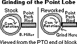 If
doing the above È doesn't help to advance
the timing quite far enough (for gas and especially methanol fuel), grinding
(and polishing) of the lobe may need to be done. Grind about .050" deep in
the surface just before the lobe (see drawing to the right ->)
and about 1/2" from the lobe to right next to the lobe, but not on the
lobe itself! A die grinder with a porting stone works excellent for doing
this. After doing this, the timing can then be advanced as far as 50º
BTDC! The alternative of doing this is to install a custom-made
flywheel- or
crank-trigger electronic ignition system.
If
doing the above È doesn't help to advance
the timing quite far enough (for gas and especially methanol fuel), grinding
(and polishing) of the lobe may need to be done. Grind about .050" deep in
the surface just before the lobe (see drawing to the right ->)
and about 1/2" from the lobe to right next to the lobe, but not on the
lobe itself! A die grinder with a porting stone works excellent for doing
this. After doing this, the timing can then be advanced as far as 50º
BTDC! The alternative of doing this is to install a custom-made
flywheel- or
crank-trigger electronic ignition system.
When advancing the ignition timing past
24º± BTDC, and if the camshaft has an automatic compression release,
it will need to be removed because the spark will occur when the exhaust
valve opens slightly to relieve some of the compression, preventing the engine
from starting. And to make the engine easier to crank over under full
compression, a high torque starter motor with separate starter and ignition
switches to prevent "kickback" will need to be used.
"Kickback" occurs when
the crankshaft/flywheel suddenly and violently rebounds or rotates in the
opposite direction, which is could bend or break the starter armature shaft
or break the aluminum starter housing. To start any engine with advanced
timing and under full compression, two separate switches will need to be
used. A push button switch to crank the engine, and an OFF-ON toggle switch
or OFF-ON rotary key switch to power the ignition. To make this work, first
crank the engine over, and while it's cranking over, choke the carburetor
(or install A-1 Miller's remote
fuel primer system), then turn on the ignition switch to "put the spark
to it." The engine should start easily every time. This method works because
the continuing spinning centrifugal force of the flywheel prevents the engine
from "kicking back" when power is being supplied to the ignition.
COMING SOON! If the points lobe inside the governor assembly or the points pushrod hole is severely worn on a Kohler engine model K482, K532 or K582 and the ignition timing cannot be fully advanced to the factory setting of 22.5º BTDC, and acquiring another governor assembly that's in better condition (if one is available) is out of the question, then the alternative is to convert the engine to A-1 Miller's custom-made and reliable flywheel-triggered 12 volt electronic ignition.
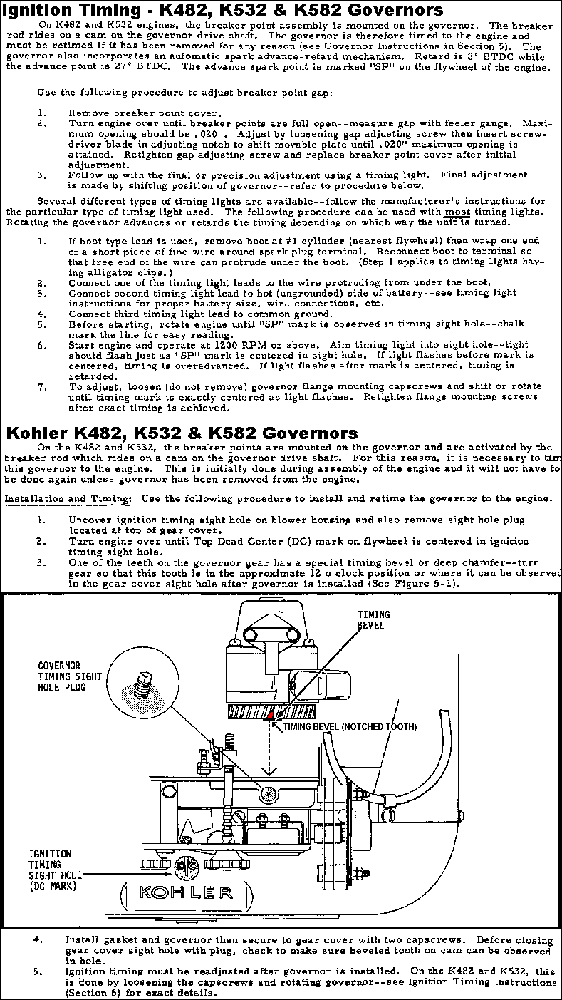
To prevent crankcase oil from
contaminating the ignition points on a Kohler engine is to install a new
[stainless steel] ignition points pushrod and/or if the hole in the block
is slightly worn, install a 3/16" I.D. neoprene rubber
O-ring over the ignition points pushrod. Place the O-ring on the outside
[of the block] and close to the engine block. The oil will travel out to
the O-ring and drip off, staying off the ignition points. But if the ignition
points pushrod hole is excessively worn, this will effect the ignition timing
as well, and the block will need to be machined for installation of a bronze
sleeve bushing, or the hole can be plugged, and solid state or a custom-made
flywheel- or
crank-trigger electronic ignition system
can be installed. (The translucent silicone rubber diaphragm seal (part
# 220074-S) is no longer available from Kohler.)
Ignition System Options - [Top of Page]
If a Kohler K-series engine originally came with ignition points and condenser/capacitor ignition, and you're looking for a more reliable and maintenance-free ignition system, well, you have these options...
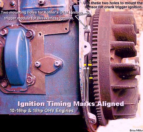 If the engine has self-energizing
magneto ignition, do away with the ignition points and condenser/capacitor
(plug the points pushrod hole), and install a
Universal Solid State
Electronic Ignition Module.
If the engine has self-energizing
magneto ignition, do away with the ignition points and condenser/capacitor
(plug the points pushrod hole), and install a
Universal Solid State
Electronic Ignition Module.

 Get that
old, antique small gas engine for general lawn & garden equipment, go-karts,
King Midget micro car, all terrain vehicles, snowmobiles,
industrial/commercial, etc., running again with 21st century technology using
100% reliable digital electronic ignition, even when new replacement parts
are cost-prohibited or obsolete. Electronic ignition can be installed on
virtually any small gas engine, regardless of the make and model. Where there's
a will, there's a way. It's mind over matter. Click here
to contact A-1 Miller's for FREE honest and accurate technical support and/or
for ordering information and payment options. Please contact A-1 Miller's
if you need part(s) and/or service(s) performed that's not listed or mentioned
in this website. [Top
of Page] [Return to previous
paragraph, section or website]
Get that
old, antique small gas engine for general lawn & garden equipment, go-karts,
King Midget micro car, all terrain vehicles, snowmobiles,
industrial/commercial, etc., running again with 21st century technology using
100% reliable digital electronic ignition, even when new replacement parts
are cost-prohibited or obsolete. Electronic ignition can be installed on
virtually any small gas engine, regardless of the make and model. Where there's
a will, there's a way. It's mind over matter. Click here
to contact A-1 Miller's for FREE honest and accurate technical support and/or
for ordering information and payment options. Please contact A-1 Miller's
if you need part(s) and/or service(s) performed that's not listed or mentioned
in this website. [Top
of Page] [Return to previous
paragraph, section or website]
FYI - I can install my custom-made flywheel- or crank-triggered electronic ignition system on virtually any older small engine and/or rewire your lawn & garden tractor, garden tractor, small engine equipment, small motorized vehicle or competition garden pulling tractor so all the electrical accessories will work correctly and the engine will start quicker, idle smoothly and rev up to full RPM with no hesitation whatsoever. I have the knowledge, skills, all the parts and tools to perform a professional job. I've rewired many customer's lawn & garden tractors, garden tractors, small engine equipment and competition garden pulling tractors through the years with great results. If you're interested, please click/tap here for contact information and directions to A-1 Miller's shop.
This is the era of modern wonders, where everything is electronic, transistorized, digitized and miniaturized. Yet even today, many competition garden pulling tractors with an older engine still use the old-fashioned breaker point ignition systems. For other people, the frustration of attempting to keep a breaker point-fired tractor in peak running condition has been enough of a reason to join the electronic/solid state electronic ignition era. Breaker point systems do have some positives, though. ignition points are cheap and somewhat easy to install. And many people are comfortable with installing their own ignition points. The bad side of using ignition points is, besides the ignition points contacts burning, pitting and wearing out, if or when the ignition points lobe on the (Kohler) camshaft and/or the ignition points pushrod become worn, this will narrow the gap on the ignition points, and retard the ignition timing. The ignition points lobe can wear so much that resetting the ignition points at the factory setting of .020" or setting the ignition timing at 20º BTDC becomes impossible. As the point gap gets too narrow, the ignition timing will become retarded (less than the factory setting of 20º BTDC), which will cause the engine to run sluggish and lose power, and when it gets too wide, the timing will become too advanced (more than the factory setting of 20º BTDC), which will cause the engine to run hotter than normal, which could cause premature engine wear and oil burning, eventually resulting in an engine rebuild. There's also less chance of a dangerous fire due to non-existence of ignition points.
IMPORTANT! Running an engine with insufficient or severely retarded ignition timing will cause accelerated internal wear and lead to oil burning over time. When the timing is retarded (spark occurs too late before the piston reaches top dead center), the fuel mixture does not have time to burn completely inside the combustion chamber, and some it exits out the exhaust. This results in several cascading issues:
On the other hand, when the timing is too advanced (beyond factory recommendation), the spark plug(s) fires too early, causing the air-fuel mixture to ignite and expand while the piston(s) is/are still moving upward. While moderate advancement of the timing increases power and efficiency, with low octane gas, going too far reduces performance, causes dangerous engine knocking (detonation) and pinging, and can severely damage the engine.
Self-energizing small engine magneto armature
ignition coils and battery-powered coils with either points and condenser
or electronic ignition must be used with a metal core spark plug wire and
a copper core/non-resistor spark plug. Most automobiles with electronic ignition
have
suppression/carbon core spark plug wires only to prevent
interference of sensitive electronic components and [AM/FM] radio static.
However, if a suppression/carbon core spark plug wire and/or
a resistor type spark
plug is used with a magneto or battery-powered ignition coil, the coil
may operate at a much higher than normal temperature (too hot to the touch),
and either the coil will fail or the engine will idle well, but hesitate
to rev up at high RPM due to the high resistance in the suppression/carbon
core spark plug wire and/or a
resistor type spark plug. And avoid
using a
suppression/carbon core spark plug wire with an electronic
ignition system on a small engine! The reason being is if the suppression/carbon
core spark plug wire becomes extremely weak and deteriorated with very high
resistance, this can cause the ignition coil and possibly the electronic
ignition control module to burn up.
With all of my Universal Solid State Electronic Ignition Module, and flywheel-triggered ignition systems (all listed below), when installed accordingly, the ignition timing is ALWAYS advanced. If it's set or installed retarded, it will NOT automatically advance as soon as the engine starts. If the timing is set retarded, the only way to advance it is by rotating an ignition plate or ignition distributor manually by hand, or automatically by a vacuum canister with intake manifold, or by centrifugal force with flyweights.
When the timing is retarded, the engine may start with no problems, but not idle or rev up too well, and it'll lack sufficient power. Also, with retarded timing, all of the fuel in the combustion chamber will not be burned. Part of the raw fuel will exit out of the exhaust, while the rest will remain in the chamber combustion and cling to the cylinder wall, causing the crankcase lubricating oil to become diluted or thin-out. When this happens, "cylinder wash down" will result. Cylinder wash down is when the gas (or diesel fuel) dilutes the light coating of oil on the cylinder wall, and the piston rings will no longer be adequately lubricated, causing direct metal to metal contact, which will cause them to wear excessively, and cause the cylinder wall have a protruding ridge towards the top, resulting in a smoky, oil burning engine overtime. Cylinder wash down can also happen to a diesel engine when the fuel injectors are purposely "turned up" to increase the fuel delivery so the engine will produce more power. This will cause a lot of black smoke be blown out the exhaust all the time (at idle and especially upon acceleration), which will result in shorter engine life, and eventually, gray exhaust smoke (crankcase oil ash) will be mixed with the black exhaust smoke (partially burned diesel fuel ash). It'll run good for a while!
But when the ignition timing is too advanced, this will cause the engine to run hotter than normal, which will likely cause the piston to swell more than usual, allowing it to make metal to metal contact against the cylinder wall, causing excessive wear and friction. And the rings will lose their expansion against the cylinder wall as well. Eventually, due to the lose-fitting piston in the cylinder, the engine (piston) will make a rattling sound and start smoking out the exhaust, and it will ultimately need to be rebuilt.
Flywheel- or crank-trigger electronic ignition delivers twice the voltage and twice the duration of spark to the spark plugs, increasing engine performance and spark plug life. No ignition points to burn, no moving parts to wear out. Epoxy molding of the ignition components makes them impervious to dirt, oil, grease and moisture. Stable timing, no need for adjustment - ever! If installed correctly, crank-trigger and flywheel-triggered stabilizes the ignition timing and will always have a strong spark with the use of microelectronics, so you won't ever have to worry about it. There'll be less of a chance of spark plug fouling, and the fuel will be burned more thoroughly. The engine will produce more horsepower and you will have more confidence that the engine will last longer. So for the utmost precision ignition timing and maintenance-free convenience, flywheel- or crank-trigger electronic ignition is the way to go! It will help the engine to idle smoother, rev up with no hesitation and run better, and produce more horsepower at open RPM (wide open throttle). Turns the stock coil into a high-performance coil without shortening the life of the coil.
Tired of changing or constantly adjusting the ignition points? Convert to the 100% digitized flywheel- or crank-trigger electronic ignition! For improved performance, easier starting, and less moving parts to leave your tractor dead on the track. Shock and moisture resistant, and all it takes is a few simple hand tools to install. In my opinion, getting rid of the ignition points and condenser/capacitor has been the best advance ever in engine technology.
Virtually Any Gas Engine Can Be Converted To the Flywheel- or Crank-Trigger Electronic Ignition!
A-1 Miller's custom-made flywheel- or crank-trigger electronic ignition kits will work with virtually any 2- or 4-cycle engine, as long as the magnetic pickup coil or 3-wire inductive proximity sensor, or the Dynatek Dyna S or electronic ignition modules can be mounted securely, and there's a trigger rotor or disc of some kind, that can also be secured in place.
If an engine is connected to a battery (and if it has a charging system to keep the battery fully charged for prolong use), and if there's room on the PTO end of the crankshaft for the ignition disc, and a place to mount the bracket for the magnetic pickup coil or 3-wire inductive proximity sensor, then the engine can be converted to flywheel- or crank-trigger electronic ignition. And the ignition disc doesn't have to be made of aluminum. If there's a steel hub mounted on the end of the crankshaft, it could be used to trigger the ignition. As long as the head(s) of the detectable target, rather if it's a small magnet, screw, pin, projection (hump) or large bolt head on the edge of a flywheel or on a rotating disc, is/are higher than the outer edge of the [steel] hub (signal detection), the magnetic pickup coil or 3-wire inductive proximity sensor will detect it/them. [Return to previous paragraph, section or website]
Kohler's Breakerless Ignition System -
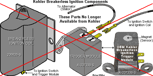 Kohler
Breakerless Ignition (and Tecumseh Cast Iron Block Engine Solid State
Ignition) are a 100% digital system and requires no mechanical or physical
contact to activate any moving parts. It operates basically on the same general
principle as crank-trigger and flywheel-triggered ignition. A trigger module
containing solid state electronics performs the same function as the breaker
points. Because there are no breaker points in this system, there are no
requirements for ignition timing. The Module Sensor, as part of the Breakerless
Ignition system, is energized by two windings on the charging stator under
the flywheel. Breakerless Ignition is pretty much maintenance-free, with
very few parts to wear out or become defective. But when it does fail, OEM
replacement parts are no longer available from any source. Apparently, there's
a good reason why Kohler stopped installing Breakerless Ignition after a
short time. Kohler's Breakerless Ignition and Tecumseh's Solid State Ignition
systems are their version of my custom-made flywheel-triggered electronic
ignition systems as described further down in this website. A-1 Miller's
crank-trigger and flywheel-triggered ignition kits can replace a defective
Breakerless Ignition and Tecumseh's Solid State ignition systems.
Kohler
Breakerless Ignition (and Tecumseh Cast Iron Block Engine Solid State
Ignition) are a 100% digital system and requires no mechanical or physical
contact to activate any moving parts. It operates basically on the same general
principle as crank-trigger and flywheel-triggered ignition. A trigger module
containing solid state electronics performs the same function as the breaker
points. Because there are no breaker points in this system, there are no
requirements for ignition timing. The Module Sensor, as part of the Breakerless
Ignition system, is energized by two windings on the charging stator under
the flywheel. Breakerless Ignition is pretty much maintenance-free, with
very few parts to wear out or become defective. But when it does fail, OEM
replacement parts are no longer available from any source. Apparently, there's
a good reason why Kohler stopped installing Breakerless Ignition after a
short time. Kohler's Breakerless Ignition and Tecumseh's Solid State Ignition
systems are their version of my custom-made flywheel-triggered electronic
ignition systems as described further down in this website. A-1 Miller's
crank-trigger and flywheel-triggered ignition kits can replace a defective
Breakerless Ignition and Tecumseh's Solid State ignition systems.

 The energizer wire that
come from the stator under the flywheel for Kohler Breakerless Ignition or
Tecumseh Solid State Electronic Ignition Module generates about 250 volts
(serious) while the engine is running at full governed speed. Actually, the
primary circuit in virtually all magneto ignition coils generate anywhere
from 200 to 400 volts. So do not touch this wire or terminal with one bare
hand and the engine itself with your other bare hand while the engine is
running! Electrocution or death could occur. It is not needed for any of
A-1 Miller's crank-trigger ignition systems. So snip off this wire or tape
up the terminal.
The energizer wire that
come from the stator under the flywheel for Kohler Breakerless Ignition or
Tecumseh Solid State Electronic Ignition Module generates about 250 volts
(serious) while the engine is running at full governed speed. Actually, the
primary circuit in virtually all magneto ignition coils generate anywhere
from 200 to 400 volts. So do not touch this wire or terminal with one bare
hand and the engine itself with your other bare hand while the engine is
running! Electrocution or death could occur. It is not needed for any of
A-1 Miller's crank-trigger ignition systems. So snip off this wire or tape
up the terminal.
Kohler engines with Breakerless Ignition are rare. In fact, out of the 1,000's of Kohler engines that were manufactured, only 92 of these originally came with Breakerless Ignition. Most originally came with points and condenser ignition because it's more reliable and produces a stronger spark. The Breakerless Ignition System was used on various Kohler engine models K181, K241, K301 and K321. The models and specification numbers of Kohler engines that originally came with Breakerless Ignition are as follows: K181-30296, 30518, 30519, 30529, 30666; K241-46513, 46536, 46566, 46578, 46591, 46613, 46614, 46615, 46624, 46634, 46640, 46651; K301-47145, 47147, 47204, 47232, 47249, 47252, 47255, 47275, 47277, 47278, 47284, 47289, 47295, 47303, 47304, 47305, 47313, 47314, 47335, 47336, 47339, 47340, 47346, 47350, 47362, 47363, 47365, 47367, 47371, 47374, 47375, 47378, 47387, 47389, 47391, 4739, 47400, 47402, 47403, 47407, 47410, 47420, 47422, 47423, 47424, 47814; K321-6006, 6008, 60105, 60121, 60124, 60125, 6013, 60131, 60132, 60133, 60176, 60187, 60189, 60201, 60213, 60239, 60275, 6051, 6053, 6055, 6058, 6071, 6079, 6081, 6088, 6093. All K90/K91, K141, K160/K161, K341 and K361 engines came with points and condenser ignition.
The Trigger Module (the part that's fastened to the bearing plate and extends over the ring gear, and is triggered by the projection (hump) or large bolt head on the edge of the flywheel) is part of the Breakerless Ignition System. To test the Breakerless Ignition Coil and Trigger Module, refer to Kohler K-series Single Cylinder Engine Service Manual TP-2379 or Kohler Breakerless Ignition Service Bulletin. If the Breakerless Ignition fails to produce a spark, the Coil and Trigger Module have been discontinued by Kohler. And if you're looking for an alternative and reliable replacement ignition system to get your engine running again, well, you have the three options below...
Stable ignition timing is a necessity in high-performance engines. In most cases, a ignition points ignition will do just fine, but when you start making big time horsepower with extreme cylinder pressures and higher RPM, the timing is critical to both the performance and life of the engine. The ignition must be triggered at a precise time in relation to the position of the piston during the compression stroke. However, the timing can get erratic or fluctuate at open RPM (wide open throttle) with the ignition points system, due to camshaft end play, clearance in both the crank and cam gears and mechanical flexing that takes place through the camshaft support pin, especially when using a high lift cam with very stiff valve springs. In fact, if you ever checked the timing on an engine with camshaft-operated ignition points using a strobe timing light, you may have noticed that the timing mark on the flywheel (or starter pulley on the PTO end) will fluctuate or "move up and down" a few degrees. And it'll fluctuate more as the engine RPM increases. This won't happen with flywheel- or crank-trigger electronic ignition. It totally eliminates spark flutter or fluctuations and erratic timing problems common with point ignitions. With flywheel- or crank-trigger electronic ignition, the "tighter" the main bearings are, the more stable the timing is.
When checking the timing with a strobe timing light on an engine with crank-trigger and flywheel-triggered electronic and main ball bearings, it's best to run the engine until it reaches normal operating temperature. The reason for this is the free play in the ball bearings is lessened as the bearings get warm, providing a more stable spark.
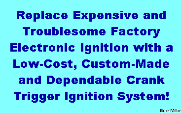 The crankshaft knows exactly
where the piston is, plus the crankshaft is the most stable component in
an engine in relation to piston position. That's why
flywheel- or
crank-trigger electronic ignition is
so important in high-horsepower/open RPM engine applications. With this ignition,
you get absolutely stable timing with 1/10th± of a degree of accuracy
from 0 to 15,000+ RPM without missing a beat (when using an electronic ignition
control module/unit (ICU) with a high capacity transistor). The 1/10th±
of a degree is the result of the oil clearance in the main bearings. With
a high capacity electronic ignition control module, the
flywheel- or
crank-trigger electronic ignition system
will work flawlessly without missing a hit even if the engine is capable
of turning up to 100,000 RPM! Because it works as fast as the speed of
electricity, which can be anywhere from about 50% to 99% of the speed of
light, depending upon the quality of the electronic components and wiring
connections. As long as the crank-trigger ignition system is installed and
the timing is set correctly, it'll help a competition pulling tractor scream
down the track. Also, with the
flywheel- or
crank-trigger electronic ignition system,
you can set the ignition timing and forget it!
The crankshaft knows exactly
where the piston is, plus the crankshaft is the most stable component in
an engine in relation to piston position. That's why
flywheel- or
crank-trigger electronic ignition is
so important in high-horsepower/open RPM engine applications. With this ignition,
you get absolutely stable timing with 1/10th± of a degree of accuracy
from 0 to 15,000+ RPM without missing a beat (when using an electronic ignition
control module/unit (ICU) with a high capacity transistor). The 1/10th±
of a degree is the result of the oil clearance in the main bearings. With
a high capacity electronic ignition control module, the
flywheel- or
crank-trigger electronic ignition system
will work flawlessly without missing a hit even if the engine is capable
of turning up to 100,000 RPM! Because it works as fast as the speed of
electricity, which can be anywhere from about 50% to 99% of the speed of
light, depending upon the quality of the electronic components and wiring
connections. As long as the crank-trigger ignition system is installed and
the timing is set correctly, it'll help a competition pulling tractor scream
down the track. Also, with the
flywheel- or
crank-trigger electronic ignition system,
you can set the ignition timing and forget it!
The flywheel- or crank-trigger electronic ignition is when the mechanical breaker points and condenser/capacitor are totally eliminated and replaced by solid state electronic components. Actually, it works on the same principle as the electronic ignition that's used in the older automobiles (before computerized ignition systems). The conventional ignition points ignition system is considered as old-fashioned technology by today's standards. Even the [high dollar] aftermarket adjustable ignition plate that's made for Chevy ignition points is considered old-fashioned by today's standards!
Using ignition points versus flywheel- or crank-trigger electronic ignition is up to you. Personally, I prefer to use the flywheel-triggered or crank-trigger ignition setup because it's very reliable and virtually maintenance-free. With conventional ignition, the ignition points will ALWAYS go bad or wear out. The contacts on ignition points can get dirty, worn, burnt, oily (oil seepage from the crankcase through the ignition points pushrod hole), out of adjustment, wet (whenever the tractor is washed off or rained upon) or even oxidized (light corrosion). The use of a (40,000 volt) high-output/performance or OEM automotive electronic ignition coil can also shorten the life of ignition points. And the condenser/capacitor can become defective.
At very open RPM, with conventional
ignition points and condenser/capacitor ignition, the ignition coil operates
at about 80% efficiency. The same is true with (40,000 volt)
high-output/performance or OEM automotive electronic ignition coils because
they require more amperage from the battery. But with crank-trigger and
flywheel-triggered ignition, using the GM 4-pin HEI, Chrysler (w/ballast
resistor) or Ford electronic ignition control module/unit
(ICU), any type of coil operates at 100% efficiency at any
RPM, which produce a much stronger spark. This is why Chevrolet refers to
their 1974-'90 electronic ignition as HEI, meaning High Energy Ignition.
The reason there's a stronger spark is because at higher RPM, there's no
condenser/capacitor to break down the voltage in the primary circuit in the
coil.
When a magnetic pickup coil is used with crank-trigger and flywheel-triggered ignition, the duration of each spark lasts about twice as long than with ignition points and condenser/capacitor ignition. And when a 3-wire inductive proximity sensor is used with crank-trigger and flywheel-triggered ignition, the spark duration is about 4 times longer than with ignition points and condenser/capacitor ignition, because a 3-wire inductive proximity sensor can detect the target, rather if it's a small screw, pin, projection (hump) or large bolt head on the edge of a flywheel or on a rotating disc, at the farther distance than a magnetic pickup coil. A longer spark duration burns the fuel more thoroughly, especially at open RPM, resulting in more power. Although a 3-wire inductive proximity sensor can be used on a stock engine running at around 4,000 RPM with no problems, it's more suited for a high-performance engine (than the magnetic pickup coil) due to its longer spark duration. In other words, a stock engine with limited RPM will not benefit from the longer spark duration. Also, the closer the magnetic pickup coil or 3-wire inductive proximity sensor is set to the target, rather if it's a small screw, pin, projection (hump) or large bolt head on the edge of a flywheel or on a rotating disc, the longer the duration will be.
Items Needed and Details on How to Install a Flywheel- or Crank-Trigger Electronic Ignition System (on virtually any gas engine) - [Top of Page]
ü A Universal Magnetic Pickup Coil,
Crankshaft Position Sensor, Tach/Speed Sensor or a 3-Wire Inductive (detects
iron/steel) Proximity Sensor. Virtually any automotive engine speed sensor
or crank position sensor will work for this system. These all work the same.
These sensors require no power from the battery or module because they
self-generate an AC signal. Be sure to use a magnetic one that produce
a small electrical current whenever a small steel (nonmagnetic) object is
passed quickly over the end of it. Most magnetic pickup coils generate 2-3
volts. Also, there needs to be a way to mount it on the engine so the air
gap/clearance and ignition timing can be set and/or adjusted. A universal
magnetic pickup coil is most common for this application. It's an engine
speed sensor (Tach Sensor) that threads in the bellhousing of a late model
truck with a Diesel engine for activation of the
tachometer. A crank position sensor is an automotive
unit that threads in the engine block and reads off a cogged wheel mounted
on the crankshaft. It's for a flywheel- or crank-trigger electronic ignition
system that's on an automobile with a computer-controlled engine that has
electronic fuel injection.
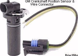
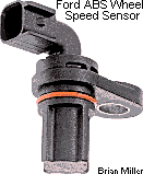
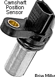 The Ford (various
1987-2009 models) ABS wheel speed sensor will work as the magnetic pickup
coil with the crank-trigger and flywheel-triggered ignition. And various
GM crank position sensors have three or more wires, but use just two wires.
(They're nothing more than a magnetic pickup coil.) The third (or other)
wire(s) is ground or neutral and really don't need to be used with crank-trigger
and flywheel-triggered ignition. When you buy a sensor, test it to see which
wires produce the electrical current, then just snip off the (useless) other
wire(s). A 3-wire inductive proximity sensor, magnetic pickup coil and crank
position sensor can be easily tested by connecting it to an
analog or
digital multimeter that's set on the lowest AC scale, then
quickly pass the head of a small steel bolt or nail back and forth across
the end of the sensor. If the analog needle fluctuates slightly or the digital
display goes up and down each time the metal object makes a pass, the sensor
is in working order. The more voltage a sensor produce, the stronger the
spark. Use a small magnet or a
telescoping magnetic pickup tool with a small magnet to
test a non-magnetic pickup coil or 3-wire hall effect proximity sensor. The
stronger the magnet, the more voltage the sensor will produce, resulting
in a stronger spark.
The Ford (various
1987-2009 models) ABS wheel speed sensor will work as the magnetic pickup
coil with the crank-trigger and flywheel-triggered ignition. And various
GM crank position sensors have three or more wires, but use just two wires.
(They're nothing more than a magnetic pickup coil.) The third (or other)
wire(s) is ground or neutral and really don't need to be used with crank-trigger
and flywheel-triggered ignition. When you buy a sensor, test it to see which
wires produce the electrical current, then just snip off the (useless) other
wire(s). A 3-wire inductive proximity sensor, magnetic pickup coil and crank
position sensor can be easily tested by connecting it to an
analog or
digital multimeter that's set on the lowest AC scale, then
quickly pass the head of a small steel bolt or nail back and forth across
the end of the sensor. If the analog needle fluctuates slightly or the digital
display goes up and down each time the metal object makes a pass, the sensor
is in working order. The more voltage a sensor produce, the stronger the
spark. Use a small magnet or a
telescoping magnetic pickup tool with a small magnet to
test a non-magnetic pickup coil or 3-wire hall effect proximity sensor. The
stronger the magnet, the more voltage the sensor will produce, resulting
in a stronger spark.
Magnetic pickup coils and proximity
sensors are very sensitive to mechanical damage (and electrical damage if
connected wrong). For magnetic pickup coils,
set the air gap/clearance from the detectable target (screw, pin or small
raised area on the rotating disc) at .010"-.060" with a brass
feeler gauge. And being 3-wire inductive
proximity sensors have a farther detection range, set the air gap/clearance
at .010"-.188". If the gap is wider than .188" (3/16") with either sensor,
the ignition system may not produce a spark or the engine could misfire at
open RPM. To prevent the possibility of an out of time spark occurrence,
the detectable target needs to be a minimum of 3/16" higher than or above
the circumference surface of a steel or cast iron rotating disc or flywheel.
Direct metal contact with either sensor could damage them. When in
doubt if a sensor is mechanically damaged, look at the end of it with the
strong magnifying glass to see any damage. If it is damaged, it needs to
be replaced. A magnetic pickup coil can be tested with a digital
multimeter set on 200m DC, with the negative lead of the meter on the white
wire of the pickup coil and positive lead on the black wire, then pass a
small steel screw or bolt over the end of the magnetic pickup coil. If the
meter shows a reading, the pickup coil is in good
condition.
Most engines are not able to start under full compression and with advanced ignition timing. One or the other must be "suppressed" in order for the engine to crank over without "kicking back" to start. Either it needs to have an automatic compression release to relieve about half the compression, then the compression will return at open upon start up, or the timing needs to be positioned at TDC, then it can automatically advance upon start up.
The only reason any engine would need the ignition timing retarded or a spark advance system is so the engine won't "kickback" when attempting to start it. "Kickback" occurs when the crankshaft/flywheel suddenly and quickly momentarily rotates in the opposite direction, which is could bend or break the starter armature shaft or the aluminum starter housing. Virtually all small gas engines nowadays have a compression relief mechanism on the camshaft (that opens the exhaust valve slightly halfway on the compression stroke), which allow the engine to crank over easily without kicking back. And most pulling engines have a long duration camshaft with the compression relief mechanism (if using a cast cam) and a heavier-than-stock [steel] flywheel. Which will also allow the engine to crank over easily without kicking back when starting. So you see, a spark advance really isn't necessary. To start any engine with advanced timing and under full compression (no automatic compression release), first crank the engine over, and while it's cranking over, choke the carburetor or (or install A-1 Miller's remote fuel primer system), then turn on the ignition switch to "put the spark it." The engine should start easily every time. The spinning centrifugal force of the flywheel prevents the engine from "kicking back" when power is supplied to the ignition.
(Added 7/6/24) On a riding mower engine with magneto ignition, if the mechanical automatic compression release (ACR) mechanism on the camshaft is broken, and with the ignition energized, the engine will most likely "kick back" every time when attempting to start it. However, there may be a way around this to get the engine to start and run without replacing the camshaft with a working compression release. If the engine is able to crank over under full compression with the spark plug wire disconnected, then first crank over the engine, choke the carburetor, and use a heavy, dry rag or heavily insulated pliers to reconnect the spark plug wire. The engine should start and run. Or, for a somewhat permanent, low-cost fix, disconnect the ignition wire from the terminal on the key switch, connect this wire to a grounded, one terminal OFF-ON [chainsaw or string trimmer] toggle switch, and when cranking the engine, choke the carburetor, and then turn on the toggle switch to "put the spark to it." This method should allow the engine to start and run every time. And if the engine has an oil pump with a screen and no slinger, the broken pieces in the crankcase should pose no problems.
Magnetic pickup coils and proximity
sensors are very sensitive to mechanical damage (and electrical damage if
connected wrong). For magnetic pickup coils,
set the air gap/clearance from the detectable target (screw, pin or small
raised area on the rotating disc) at .010"-.060" with a brass
feeler gauge. And being 3-wire inductive
proximity sensors have a farther detection range, set the air gap/clearance
at .010"-.188". If the gap is wider than .188" (3/16") with either sensor,
the ignition system may not produce a spark or the engine could misfire at
open RPM. To prevent the possibility of out of time spark occurrence, the
detectable target needs to be a minimum of 3/16" higher than or above the
circumference surface of the steel or cast iron rotating disc or flywheel.
Direct metal contact with either sensor could damage them. When in
doubt if a sensor is mechanically damaged, look at the end of it with the
strong magnifying glass to see any damage. If it is damaged, it needs to
be replaced. A magnetic pickup coil can be tested with a digital
multimeter set on 200m DC, with the negative lead of the meter on the white
wire of the pickup coil and positive lead on the black wire, then pass a
small steel screw or bolt over the end of the magnetic pickup coil. If the
meter shows a reading, the pickup coil is in good
condition.
Electronic Ignition Control Module/Unit (ICU) Wiring Connections/Diagrams with a Magnetic Pickup Coil and 3-Wire Proximity Sensor [Return to previous paragraph, section or website]
IMPORTANT: Most failures of a battery-powered ignition coils and/or electronic ignition control modules are caused by either the use of suppression/carbon-core spark plug wire(s), resistor-type spark plug(s), or overcharging of the electrical system due to a defective voltage rectifier/regulator or defective [automotive] battery. Therefore, if it's not already equipped, it's best to install an ammeter/amp gauge to monitor the charging system. Also, any coil will burn up if the ignition switch is left on with the points closed for more than a few minutes with the engine not running. To prevent this from possibly happening and/or for security reasons, use an OFF-ON key switch and/or a master disconnect switch with a removable key instead of just an OFF-ON toggle switch to power the ignition system. Also, the coil could burn up if the charging system continually overcharge due to a defective voltage rectifier/regulator or a defective [automotive] battery.
Wiring Connections/Diagram for the GM 4-pin HEI Electronic Ignition Control Module with the Cube-shaped 3-Wire Inductive Proximity Sensor
This electronic ignition system requires 12 volts DC negative ground of power. This high-performance ignition system have been thoroughly tested under extreme conditions, and produces a stable and a very strong spark, even with a stock ignition coil, helping the engine to start quicker, idle smoothly and rev up to full RPM with no hesitation whatsoever. In order for the ordinary/stock GM 4-pin HEI module help the engine to rev up at open speed, it must be used with a high-output cube-shaped 3-wire inductive proximity sensor, and can be used with virtually any ignition coil, regardless of the ohm resistance or voltage output, and best to use a metal core spark plug wire and non-resister type spark plug gapped at .035". This concept revolutionizes the use of this small, compact and versatile module! This is a thoroughly tested, researched and proven reliable ignition system invented by A-1 Miller's for ordinary lawn & garden engines and competition pulling engines. The systems below can be used with virtually any ignition coil with a minimum 0.4 ohm internal resister, and best to use a metal core spark plug wire and non-resister type spark plug gapped at .035" for a strong spark. (This system does NOT have a built-in timing retard.)
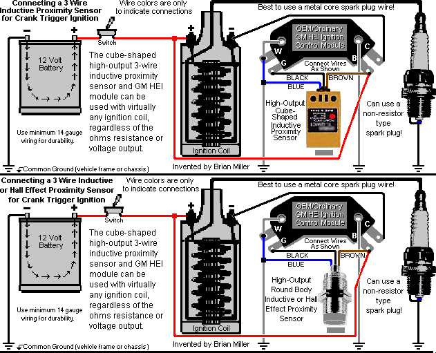 Connect the Black wire
on the sensor to the [G] terminal on the module.
Connect the Black wire
on the sensor to the [G] terminal on the module.
Chrysler/Dodge/Plymouth (MOPAR) Electronic Ignition Control Module/Unit Wiring Connections/Diagram with a Magnetic Pickup Coil
This electronic ignition system requires 12 volts DC negative ground of power. This module requires a minimum 1.2 ohm ballast resistor to prevent from burning up unit. This high-performance ignition system have been thoroughly tested under extreme conditions, and produces a stable and a very strong spark, even with a stock ignition coil, helping the engine to start quicker, idle smoothly and rev up to full RPM with no hesitation whatsoever. Can be used with virtually any magnetic pickup coil or proximity sensor and ignition coil, regardless of the ohm resistance or voltage output , and best to use a metal core spark plug wire and non-resister type spark plug gapped at .035". (This system does NOT have a built-in timing retard.)
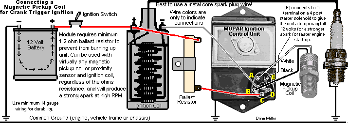 Connect the wires on the magnetic
pickup coil to the [A] and [B] terminals on the module. NOTE:
Due to
electrical
polarity of certain magnetic pickup coils, if a weak spark occurs and/or
if the engine fails to rev up, reverse the wires on the magnetic pickup coil
to produce a stronger spark so the engine will start quick, idle smoothly
and rev at open RPM.
Connect the wires on the magnetic
pickup coil to the [A] and [B] terminals on the module. NOTE:
Due to
electrical
polarity of certain magnetic pickup coils, if a weak spark occurs and/or
if the engine fails to rev up, reverse the wires on the magnetic pickup coil
to produce a stronger spark so the engine will start quick, idle smoothly
and rev at open RPM.
Chrysler/Dodge/Plymouth (MOPAR) Electronic Ignition Control Module /Unit Wiring Connections/Diagram with a 3-Wire Inductive or Hall Effect Proximity Sensor
This electronic ignition system requires 12 volts DC negative ground of power. This module requires a minimum 1.2 ohm ballast resistor to prevent from burning up unit. This high-performance ignition system have been thoroughly tested under extreme conditions, and produces a stable and a very strong spark, even with a stock ignition coil, helping the engine to start quicker, idle smoothly and rev up to full RPM with no hesitation whatsoever. Can be used with virtually any magnetic pickup coil or proximity sensor and ignition coil, regardless of the ohm resistance or voltage output , and best to use a metal core spark plug wire and non-resister type spark plug gapped at .035". (This system does NOT have a built-in timing retard.)
 Connect the Black and
Blue wires on the sensor to the
[A] and [B] terminals on the module. NOTE: It shouldn't
matter how the Black and Blue wires are mistakenly
connected to the [A] and [B] terminals, but if a weak spark
occurs and/or if the engine fails to rev up, reverse these wires to produce
a stronger spark so the engine will start quick, idle smoothly and rev at
open RPM.
Connect the Black and
Blue wires on the sensor to the
[A] and [B] terminals on the module. NOTE: It shouldn't
matter how the Black and Blue wires are mistakenly
connected to the [A] and [B] terminals, but if a weak spark
occurs and/or if the engine fails to rev up, reverse these wires to produce
a stronger spark so the engine will start quick, idle smoothly and rev at
open RPM.
 Some proximity sensors have
an LED (Light Emitting Diode) on the rear of unit. If the NPN
(Negative-Positive-Negative) inductive proximity sensor is wired correctly,
the LED will illuminate when in close proximity to the detectable target.
This is when spark occurs. If the light stays on when the sensor is not in
close proximity of the target and goes off when in close proximity of the
target, then a PNP (Positive-Negative-Positive) type of sensor is being used.
Click/tap here to print out this wiring
diagram/instructions.
Some proximity sensors have
an LED (Light Emitting Diode) on the rear of unit. If the NPN
(Negative-Positive-Negative) inductive proximity sensor is wired correctly,
the LED will illuminate when in close proximity to the detectable target.
This is when spark occurs. If the light stays on when the sensor is not in
close proximity of the target and goes off when in close proximity of the
target, then a PNP (Positive-Negative-Positive) type of sensor is being used.
Click/tap here to print out this wiring
diagram/instructions.
Ford / Mercury / Lincoln Electronic Ignition Control Module/Unit Wiring Connections/Diagram with a Magnetic Pickup Coil
This electronic ignition system requires 12 volts DC negative ground of power. This high-performance ignition system have been thoroughly tested under extreme conditions, and produces a stable and a very strong spark, even with a stock ignition coil, helping the engine to start quicker, idle smoothly and rev up to full RPM with no hesitation whatsoever. Can be used with virtually any magnetic pickup coil or proximity sensor and ignition coil, regardless of the ohm resistance or voltage output , and best to use a metal core spark plug wire and non-resister type spark plug gapped at .035". (This system does NOT have a built-in timing retard.)
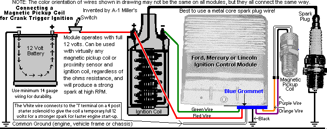 Connect the
Orange and
Purple wires on module to either wire
on the magnetic pickup coil. NOTE: Due to
electrical
polarity of certain magnetic pickup coils, if a weak spark occurs and/or
if the engine fails to rev up, reverse the wires on the magnetic pickup coil
to produce a stronger spark so the engine will start quick, idle smoothly
and rev at open RPM.
Connect the
Orange and
Purple wires on module to either wire
on the magnetic pickup coil. NOTE: Due to
electrical
polarity of certain magnetic pickup coils, if a weak spark occurs and/or
if the engine fails to rev up, reverse the wires on the magnetic pickup coil
to produce a stronger spark so the engine will start quick, idle smoothly
and rev at open RPM.
Ford / Mercury / Lincoln Electronic Ignition Control Module/Unit Wiring Connections/Diagram with a 3-Wire Inductive or Hall Effect Proximity Sensor
This electronic ignition system requires 12 volts DC negative ground of power. This high-performance ignition system have been thoroughly tested under extreme conditions, and produces a stable and a very strong spark, even with a stock ignition coil, helping the engine to start quicker, idle smoothly and rev up to full RPM with no hesitation whatsoever. Can be used with virtually any magnetic pickup coil or proximity sensor and ignition coil, regardless of the ohm resistance or voltage output, and will produce a strong spark. This system can be used with virtually any ignition coil with a minimum 0.4 ohm internal resister, and best to use a metal core spark plug wire and non-resister type spark plug gapped at .035" for a strong spark. (This system does NOT have a built-in timing retard.)
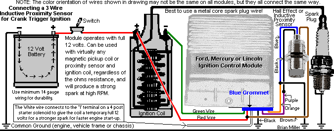 Connect the Black and
Blue wires on sensor to the
Orange and
Purple wires on module. NOTE: It shouldn't
matter how the Black and Blue wires are mistakenly
connected to the Orange and
Purple wires, but if a weak spark occurs and/or
if the engine fails to rev up, reverse these wires to produce a stronger
spark so the engine will start quick, idle smoothly and rev at open RPM.
Some proximity sensors have
an LED (Light Emitting Diode) on the rear of unit. If the NPN
(Negative-Positive-Negative) inductive proximity sensor is wired correctly,
the LED will illuminate when in close proximity to the detectable target.
This is when spark occurs. If the light stays on when the sensor is not in
close proximity of the target and goes off when in close proximity of the
target, then a PNP (Positive-Negative-Positive) type of sensor is being used.
Click/tap here to print out this wiring
diagram/instructions. NOTE: The color orientation of the wires shown
in the drawing above may not be the same on all modules, but they all connect
the same way.
Connect the Black and
Blue wires on sensor to the
Orange and
Purple wires on module. NOTE: It shouldn't
matter how the Black and Blue wires are mistakenly
connected to the Orange and
Purple wires, but if a weak spark occurs and/or
if the engine fails to rev up, reverse these wires to produce a stronger
spark so the engine will start quick, idle smoothly and rev at open RPM.
Some proximity sensors have
an LED (Light Emitting Diode) on the rear of unit. If the NPN
(Negative-Positive-Negative) inductive proximity sensor is wired correctly,
the LED will illuminate when in close proximity to the detectable target.
This is when spark occurs. If the light stays on when the sensor is not in
close proximity of the target and goes off when in close proximity of the
target, then a PNP (Positive-Negative-Positive) type of sensor is being used.
Click/tap here to print out this wiring
diagram/instructions. NOTE: The color orientation of the wires shown
in the drawing above may not be the same on all modules, but they all connect
the same way.
Advertisement: (Prices are subject to change without notice.)
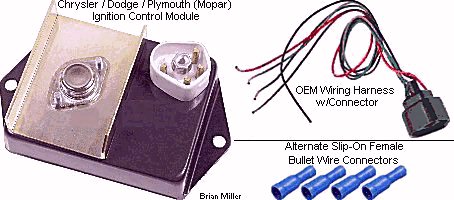 New High Quality Chrysler/Dodge/Plymouth (MOPAR) Electronic
Ignition Control Module/Unit for a custom crank- or flywheel-triggered electronic
ignition to use with virtually any small gas engine, automotive, and virtually
any gas engine. Requires 12 volts DC negative ground of power and a minimum
1.2 ohm ballast resistor to prevent burning up this module.
Click/tap here to learn how to check the ohm
resistance in a ballast resistor. This module can be used with the magnetic
pickup coil or proximity sensor and virtually any ignition coil, regardless
of the ohm resistance or voltage output, for a very strong spark (even with
a stock coil), which will help the engine to start quicker, idle smoothly
and rev up to full RPM with no hesitation whatsoever. Turns the stock coil
into a high-performance coil without shortening the life of the coil. A metal
core spark plug wire and copper core/non-resistor spark plug should be used
with virtually any ignition system to guarantee a strong spark and from burning
up the coil. Click/tap here to learn how to
check the ohm resistance in a spark plug wire. Actual weight of module:
14 oz. Click/tap here for wiring diagrams.
$20.00 each, plus shipping & handling. New High Quality Chrysler/Dodge/Plymouth (MOPAR) Electronic
Ignition Control Module/Unit for a custom crank- or flywheel-triggered electronic
ignition to use with virtually any small gas engine, automotive, and virtually
any gas engine. Requires 12 volts DC negative ground of power and a minimum
1.2 ohm ballast resistor to prevent burning up this module.
Click/tap here to learn how to check the ohm
resistance in a ballast resistor. This module can be used with the magnetic
pickup coil or proximity sensor and virtually any ignition coil, regardless
of the ohm resistance or voltage output, for a very strong spark (even with
a stock coil), which will help the engine to start quicker, idle smoothly
and rev up to full RPM with no hesitation whatsoever. Turns the stock coil
into a high-performance coil without shortening the life of the coil. A metal
core spark plug wire and copper core/non-resistor spark plug should be used
with virtually any ignition system to guarantee a strong spark and from burning
up the coil. Click/tap here to learn how to
check the ohm resistance in a spark plug wire. Actual weight of module:
14 oz. Click/tap here for wiring diagrams.
$20.00 each, plus shipping & handling.
New 1.6 ohm Ballast Resistor for use with Chrysler module (listed above) to prevent burning up unit. $8.00 each, plus shipping & handling.
|
Flywheel- or Crank-Trigger Ignition Will Work on Virtually Any Single- or Multi-Cylinder Gas Spark-Ignited Engine.
Degree Increments for a Super Spacer or Table with a Self-Centering
3-Jaw Chuck -
The chart below is for installing multiple detectable trigger targets (screws,
pins or magnets) in the ignition disc for a crank- or flywheel-triggered
ignition system. This chart also come in handy for drilling multiple holes
of equal spacing in axle flanges and other things. NOTE:
The degrees shown is not for the spark to occur at 0º TDC for each cylinder.
They are the locations of the spark for each cylinder so they will have equal
timing or exact distance of spark between them. And the reason 7 holes is
not shown is because 360º cannot be easily divided equally into 7
spaces.
| Number of holes to be drilled -> | 1st | 2nd | 3rd | 4th | 5th | 6th | 7th | 8th | 9th |
| For a 2 cylinder engine or 2 holes -> | 0º | 180º | |||||||
| For a 3 cylinder engine or 3 holes -> | 0º | 120º | 240º | ||||||
| For a 4 cylinder engine or 4 holes -> | 0º | 90º | 180º | 270º | |||||
| For 5 holes -> | 0º | 72º | 144º | 216º | 288º | ||||
| For a 6 cylinder engine or 6 holes -> | 0º | 60º | 120º | 180º | 240º | 300º | |||
| For an 8 cylinder engine or 8 holes -> | 0º | 45º | 90º | 135º | 180º | 225º | 270º | 315º | |
| For 9 holes -> | 0º | 40º | 80º | 120º | 160º | 200º | 240º | 280º | 320º |
For a multi-cylinder engine, when each detectable trigger target (screw, pin or magnet) is equally spaced apart in the ignition disc and the timing for each target is precisely aligned when its piston is at whatever degrees BTDC it's supposed be, they will fire at whatever degrees BTDC for that piston. It wouldn't matter if a screw creates a spark when the piston that isn't aligned with it or near TDC because there wouldn't be any compression at the position. It'll be a multiple, but wasted spark. This is why MSD (MSD Performance) stands for Multiple Spark Discharge. Also, being the timing will be in the advanced setting at all times with no retard (and no automatic compression release), two switches will be required to start the engine. One being a momentary push button starter switch. to crank the engine, and the other an OFF-ON toggle switch or OFF-ON rotary key switch to power the ignition. To start the engine, first crank it over, and while it's cranking, choke the carburetor (or install A-1 Miller's remote fuel primer system), and then turn on the ignition switch to "put the spark it." The engine should start easily and quickly every time. This works because the spinning centrifugal force of the heavy flywheel prevents the engine from "kicking back" when power is first supplied to the ignition. If the engine has an automatic compression release, this will not need to be done.
When using a magnetic pickup coil or a Normally Open 3-wire inductive proximity sensor for a multi-cylinder engine, a steel sprocket can be used as the trigger disc. The pickup coil or sensor will detect the [raised] sprocket teeth as the triggering objects. And being sprocket teeth are equally spaced apart, they're already degreed in. Use an even number teeth sprocket for an even numbered spark engine, and an odd number teeth sprocket for an odd numbered spark engine. Just grind away the teeth between the ones that needs to make the spark for each cylinder. But be sure to grind away the metal so the disc will maintain perfect balance.
Crank-trigger and flywheel-triggered ignition will spark on the compression
stroke for each piston when used on a multiple cylinder engine. It'll also
work excellent on any 2-cycle engine, because it fires on every stroke of
the piston. On a opposed twin or two cylinder engine, use just one Chrysler
or Ford electronic ignition control module/unit (ICU), one
magnetic pickup coil or 3-wire inductive
proximity sensor, one detectable target (screw or pin) in the
ignition disc located at approximately 20º BTDC on the compression for
the #1 cylinder. It'll spark for the #2 cylinder at 20º BTDC on the
compression stroke, too. And you could install two standard-output/stock
automotive ignition coils, one for each cylinder. Wire them together as you
would for one coil. As the detectable target (screw or pin) pass the pickup
coil, a spark will be produced for each cylinder, one piston being on the
compression stroke and the other on the exhaust stroke and vice-versa. It'll
work identically the same as Briggs & Stratton's Magnetron™ ignition
on their opposed twin cylinder flathead (valves in block) engines. Because
the Briggs opposed twins use a single ignition coil. By the way, the stock
timing on Briggs engines for gas is set at 11º BTDC.

 To advance the
timing for methanol fuel, a special-made 3/16" square
offset flywheel key must be used. Offset flywheel keys
are originally made for racing go-karts and Junior Dragsters with the 5hp
Briggs & Stratton engine. They come in 2º, 4º, 6º and
8º increments. Do a Google search for an
offset flywheel key. Use the 6º key for a setting
of 17º BTDC (11º + 6º = 17º).
To advance the
timing for methanol fuel, a special-made 3/16" square
offset flywheel key must be used. Offset flywheel keys
are originally made for racing go-karts and Junior Dragsters with the 5hp
Briggs & Stratton engine. They come in 2º, 4º, 6º and
8º increments. Do a Google search for an
offset flywheel key. Use the 6º key for a setting
of 17º BTDC (11º + 6º = 17º).
For a Kohler Magnum or any other make of engine with fixed solid state electronic ignition, to advance the ignition timing when burning either E-85 or methanol fuel, either an offset flywheel key will need to be installed, or a new keyway will need to be broached in the flywheel taper a several degrees advanced from the original keyway. A special-made offset woodruff flywheel key will need to be used when advancing the ignition timing on a Kohler Magnum engine. Precise calculation will need to be made to determine the amount of offset in the key, or where the new keyway should be. If cutting a new keyway, the original keyway will need to be filled-in with either bronze brazing or steel stock the same width as the keyway silver-soldered in place to prevent the metal from breaking next to the original keyway when broaching the new keyway slot.
If installed correctly, nothing could possibly go wrong with the flywheel- or crank-trigger electronic ignition system. Mainly because everything is totally sealed. There's no moving parts to wear and it could very well outlast the life of a typical tractor, even when used in high-performance conditions! It's virtually maintenance-free, extremely reliable. That's why auto manufacturers, virtually all small engine manufacturers (Kohler's Magnum engines ignition system operates much like crank-trigger and flywheel-triggered ignition) and most high-performance/racing vehicles nowadays use electronic [or better yet, computerized] ignition. Plus it's something fancy to show off. It's powered by full 12 volts and features a more stable spark than the convention point ignition. You can also use your existing standard ignition coil. And remember, a (40,000 volt) high-output/performance or OEM automotive electronic ignition coil will draw more power from the battery.
Crank-trigger and flywheel-triggered ignition will work on virtually any small engine, but only if there's room on the crankshaft (preferably the PTO end, which is opposite the flywheel end) for mounting of the rotating disc that contains the detectable target (screw, pin, magnet, or small raised area on the rotating disc) (see below Ê). The trigger screw(s) or small magnet can also be fastened onto the factory flywheel. Be sure to allow the head of [each] screw extend approximately 1/8" above the outer edge of the flywheel to prevent an out of time spark occurrence. And when mounting the magnetic pickup coil or 3-wire inductive proximity sensor, make sure it's mounted rigid and stable to prevent erratic timing fluctuations.
On a single cylinder engine, this type of ignition will produce a spark on both the compression and exhaust strokes, which is harmless. Camshaft driven point ignitions only spark during the compression stroke. By the way, Kohler engine is mentioned here only as an example, because they're most common in garden tractor pulling.
A-1 Miller's custom-made flywheel- or crank-trigger electronic ignition system is nothing to be afraid of. Once you understand how it works, it's actually quite simple and you'd feel more confident using it. Also, once you've tried this type of ignition, you'd be reluctant to go back to ignition points. If the crank-trigger and flywheel-triggered ignition is installed correctly on an engine and the timing is set right, it'll bring a pulling tractor to life and help it scream down the track! But if an engine already have a factory-installed solid state electronic ignition that is triggered by the flywheel, you really don't need crank-trigger and flywheel-triggered ignition0. Factory-installed flywheel-triggered ignitions are very stable, reliable and they produce a strong spark. But if you're installing a machined steel flywheel with no detector/trigger magnets or pins on an engine that originally came with solid state electronic ignition and/or there's no provisions (no threaded bolt holes present) on the block to install ignition points, you will need the flywheel- or crank-trigger electronic ignition system.
Set the ignition timing according to piston travel in the cylinder, as mentioned earlier in this website. Install a timing degree indicator mark with a black or metallic permanent ink marker (Sharpie, Magic Marker, Marks-A-Lot, etc.) on the disc and a mark on the engine block, then make a final check of the ignition timing with the engine running using a strobe timing light. The timing light connects to the battery posts and spark plug wire.
How It Works:
The magnetic pickup coil or 3-wire inductive proximity sensor is able to detect the presence of the detectable target (screw, pin, small magnet, or small raised area on the rotating disc) without any physical contact. Each time the detectable target in the rotating disc passes the magnetic pickup coil or 3-wire inductive proximity sensor, this generates a small electrical current within the pickup coil or sensor. This current is sent in the form of a signal to the electronic ignition control module/unit (ICU); within, a transistor opens the primary circuit in the ignition coil and the spark occurs. All this happens at the speed of electricity, which can be anywhere from about 50% to 99% of the speed of light, depending upon the quality of the electronic components and wiring connections. Each module provide open RPM. The conventional ignition points and condenser/capacitor ignition system is less responsive. When wired correctly, it's normal for the flywheel- and crank-trigger ignition systems to make a spark when first powered up. And if it makes a spark as the sensor passes the metal target object, then the ignition system is working as it should.
Checking for Spark -
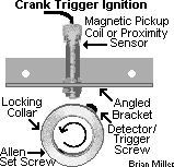

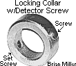 Because this
system produce a spark at very low cranking speeds, once installed, you can
check for spark simply by rotating the crankshaft or rotating disc back and
forth by hand so the steel detectable target (screw, pin, small magnet, or
small raised area on the rotating disc) pass the
magnetic pickup coil or 3-wire inductive
proximity sensor. But turn the ignition switch on first. Also,
after the engine is ran, and because there may be some raw fuel remaining
in the combustion chamber, crank-trigger and flywheel-triggered ignition
will produce a single spark each time the ignition switch is turned on. Sometimes
this spark will make the engine go "POOF", which is harmless in most cases.
Because this
system produce a spark at very low cranking speeds, once installed, you can
check for spark simply by rotating the crankshaft or rotating disc back and
forth by hand so the steel detectable target (screw, pin, small magnet, or
small raised area on the rotating disc) pass the
magnetic pickup coil or 3-wire inductive
proximity sensor. But turn the ignition switch on first. Also,
after the engine is ran, and because there may be some raw fuel remaining
in the combustion chamber, crank-trigger and flywheel-triggered ignition
will produce a single spark each time the ignition switch is turned on. Sometimes
this spark will make the engine go "POOF", which is harmless in most cases.
How to Test if a GM 4-pin HEI, Chrysler (w/ballast resistor) or Ford Electronic Ignition Control Module/Unit is Functioning or Not -
 To test if a GM 4-pin HEI, Chrysler
(w/ballast resistor) or Ford electronic ignition control module is functioning
or not, connect a fully charged 1.5 volt [flashlight] battery to the two
terminals on the module that connects to the
magnetic pickup coil or 3-wire inductive
proximity sensor (it doesn't matter which of the two terminals
is connected to the battery, but disconnect the sensor first!) and connect
the other terminals/wires on the module as shown in the diagrams above. With
the battery connected, a constant, continuous array of sparks should result
at the spark plug's tip. Don't connect the flashlight battery with the
magnetic pickup coil connected! It'll burn it up! Anyway, this test proves
only if the module is functioning or not. It won't show if it's in good working
condition. The connected battery should create a continuous spark at the
spark plug's tip. (FYI - The continuous spark will come in handy as a temporary
or replacement pilot light, such as to ignite a burner in a gas stove/heater
or
forced air heater when the factory igniter unit has failed.)
And don't use a
battery charger alone to supply the power to check for
spark or test a module for crank- or flywheel-triggered ignition. Battery
chargers constantly switch between high to low voltage at 60 cycles per second.
The module for the crank- or flywheel-triggered ignition sees this as the
ignition being switched on and off, resulting in a constant, continuous array
of sparks at the spark plug's tip. Therefore, only a fully charged 12 volt
battery should be used for testing.
To test if a GM 4-pin HEI, Chrysler
(w/ballast resistor) or Ford electronic ignition control module is functioning
or not, connect a fully charged 1.5 volt [flashlight] battery to the two
terminals on the module that connects to the
magnetic pickup coil or 3-wire inductive
proximity sensor (it doesn't matter which of the two terminals
is connected to the battery, but disconnect the sensor first!) and connect
the other terminals/wires on the module as shown in the diagrams above. With
the battery connected, a constant, continuous array of sparks should result
at the spark plug's tip. Don't connect the flashlight battery with the
magnetic pickup coil connected! It'll burn it up! Anyway, this test proves
only if the module is functioning or not. It won't show if it's in good working
condition. The connected battery should create a continuous spark at the
spark plug's tip. (FYI - The continuous spark will come in handy as a temporary
or replacement pilot light, such as to ignite a burner in a gas stove/heater
or
forced air heater when the factory igniter unit has failed.)
And don't use a
battery charger alone to supply the power to check for
spark or test a module for crank- or flywheel-triggered ignition. Battery
chargers constantly switch between high to low voltage at 60 cycles per second.
The module for the crank- or flywheel-triggered ignition sees this as the
ignition being switched on and off, resulting in a constant, continuous array
of sparks at the spark plug's tip. Therefore, only a fully charged 12 volt
battery should be used for testing.
How to Check for Spark with the GM 4-pin HEI, Chrysler (w/ballast resistor) or Ford Modules -
After either ignition system is installed on the engine and electricity is supplied, simply rotate the flywheel, pulley, etc., containing the detectable target (screw, pin, small magnet, or small raised area on the rotating disc) on the crankshaft back and forth by hand. Each time the screw passes the sensor, spark should occur. NOTE: Do not use a battery charger alone to perform this test. Battery chargers constantly switch between high and low voltage at 60 cycles per second, and the module sees this as the ignition being switched on and off resulting in a continuous, constant array of sparks. By the way - I have not received any complaints from our customers or the readers of this website concerning the crank-trigger and flywheel-triggered ignition about their engine(s) running erratic or misfiring at open RPM, unless of course, the sensor has too much clearance or they installed a defective module.
A simple and precise way to set the ignition timing STATICALLY (engine not running) for either sensor/module -
How to accurately set the ignition timing STATICALLY (engine not running) for the GM 4-pin HEI, Chrysler (w/ballast resistor) or Ford modules - (This is also how to test if the module is functioning or not.)
How to precisely set the ignition timing DYNAMICALLY (engine running) with a timing light for the GM 4-pin HEI, Chrysler (w/ballast resistor) or Ford modules. (This is the most accurate way to set the timing.) NOTE: Timing can be checked, but not set while the engine is running!
Advertisement: (Prices are subject to change without notice.)
| Click here to contact A-1 Miller's Performance Enterprises to place an order, send your parts for repairing, and/or for FREE professional and honest technical customer service assistance and support and payment options. Please contact A-1 Miller's if you need part(s) and/or service(s)(s) performed that's not listed or mentioned in this website. |
Get that
old, antique small gas engine running again with 21st century
technology using 100% reliable digital electronic ignition, even when new
replacement parts are obsolete or cost-prohibited. Electronic ignition can
be installed on virtually any small gas engine. Where there's a will, there's
a way. It's mind over matter.
Click here to contact A-1 Miller's
Performance Enterprises to place an order, send your parts for repairing,
and/or for FREE professional and honest technical customer service assistance
and support and payment options.
[Top of Page]
[Return to previous paragraph, section
or website]
FYI - I can install any of my custom-made flywheel- or crank-trigger electronic ignition systems on your older small gas engine and/or rewire your lawn & garden tractor, small engine equipment, small motorized vehicle or competition garden pulling tractor so all the electrical accessories will work and if everything else is in good condition with the engine (compression, carburetion, etc.), the engine should start quicker, idle smoothly and rev up to full RPM with no hesitation whatsoever. I have the knowledge, skills, all the parts and tools to perform a professional job. I've rewired many customer's lawn & garden tractors, small engine equipment and competition garden pulling tractors many times with great results. If you're interested, please click/tap here for contact information and directions to A-1 Miller's shop.
This is the era of modern wonders, where everything is transistorized, digitized and miniaturized. Yet even today, many garden tractor pullers still use the old-fashioned and outdated breaker point ignition system on their competition garden pulling tractors, even when their sanctioning club's rules allow crank trigger ignition. For other people who use ordinary lawn and garden small engine equipment, the frustration of attempting to keep a breaker point-fired engine in peak running condition has been enough of a reason to join the electronic era. Breaker point systems do have some positives, though. Points and condensers are cheap and somewhat easy to install. And many people are comfortable with installing their own points and condensers. The bad side of using points is, besides the points contacts burning, pitting and wearing out, if or when the point gap gets too narrow, the ignition timing can get retarded, and when it gets too wide, the timing will become too advanced.
NOTE: With all of my crank-trigger ignition systems (all listed below), when installed accordingly, the ignition timing is ALWAYS advanced. If it's set or installed retarded, it will NOT automatically advance as soon as the engine starts. If the timing is set retarded, the only way to advance it is by rotating an ignition plate or ignition distributor manually by hand, or automatically by a vacuum canister with intake manifold, or by centrifugal force with flyweights.
When the timing is retarded, the engine may start with no problems, but not idle or rev up too well, and it'll lack sufficient power. Also, with retarded timing, all of the fuel in the combustion chamber will not be burned. Part of the raw fuel will exit out of the exhaust, while the rest will remain in the chamber combustion and cling to the cylinder wall, causing the crankcase lubricating oil to become diluted or thin-out. When this happens, "cylinder wash down" will result. Cylinder wash down is when the gas (or diesel fuel) dilutes the light coating of oil on the cylinder wall, and the piston rings will no longer be adequately lubricated, causing direct metal to metal contact, which will cause them to wear excessively, and cause the cylinder wall have a protruding ridge towards the top, resulting in a smoky, oil burning engine overtime. Cylinder wash down can also happen to a diesel engine when the fuel injectors are purposely "turned up" to increase the fuel delivery so the engine will produce more power. This will cause a lot of black smoke be blown out the exhaust all the time (at idle and especially upon acceleration), which will result in shorter engine life, and eventually, gray exhaust smoke (crankcase oil ash) will be mixed with the black exhaust smoke (resembles partially burnt diesel fuel ash exhaust). It'll run good for a while!
But when the ignition timing is too advanced, this will cause the engine to run too hot, which will likely cause the piston(s) to swell larger than normal, allowing it/them to make metal to metal contact against the cylinder wall, resulting in excessive wear. When the piston wears, it will be too loose in the cylinder, causing a rattling sound. Plus, due to the worn piston, the rings will loose their square edge against the cylinder wall, and become rounded, which will allow oil to be moved to the top of the piston instead of being scraped back into the crankcase. (This is the how the 2nd or middle ring works.) Plus, the rings will lose their expansion against the cylinder wall as well. Eventually, the engine will blow blue or gray smoke out the exhaust, and it will ultimately need to be rebuilt.
If electronic ignition is installed correctly, when the ignition is triggered by the flywheel, this stabilizes the timing, so you won't ever have to worry about it changing. The engine will produce more horsepower and you will have more confidence that the engine will last longer. (As long as an air filter is used, the carburetor is adjusted correctly and the crankcase oil is changed regularly.) So for the utmost precision ignition timing and maintenance-free convenience, flywheel-triggered electronic ignition is the way to go! The high-performance electronic ignition systems offered in this website produce a stable and a very strong spark with the use of microelectronics. They will help the engine to start quicker, idle smoothly and rev up to full RPM with no hesitation whatsoever. Turns the stock coil into a high-performance coil without shortening the life of the coil.
As a matter of fact, electronic ignition works so well, this is why most small engine manufacturers dropped their points and condenser ignition and went to electronic ignition in 1982. And most automotive manufacturers started installing electronic ignition in their vehicles since 1972 (Chrysler products) and 1974 (GM and Ford products).
Tired of cleaning, changing or constantly readjusting the ignition points, and replacing the condenser? Well, upgrade/convert the engine with an A-1 Miller's custom-made, maintenance-free and weather-proof 100% digitized flywheel-triggered electronic ignition system! Shock and moisture resistant, and all it takes is a few simple hand tools to install. In my opinion, getting rid of the points and condenser/capacitor have been the best advance ever in engine technology. FYI - I've designed and sold many various custom-made electronic ignition systems to customers for the past several years and haven't received one complaint about the performance of their engine. Because I use technology that I learned from experiences with my competitive competition pulling tractors (engines) to help factory stock lawn & garden engines perform better. And as a matter of fact, other people have emailed or called me to complain to me about my competitor's replacement electronic ignition systems for Tecumseh engines. They said their technical customer service assistance to resolve the problem was of no help. No joke. Apparently, my competitors haven't quite figured it out yet.
FYI - Kohler's Breakerless Ignition and Tecumseh's (cast iron engine) Solid State Ignition (SSI) systems use a key switch that's also made for a self-energizing magneto or solid state electronic ignition system. Unlike the key switch for a battery-powered ignition system, the Breakerless Ignition is self-energizing, and to kill the engine, the key switch grounds out or shorts the [low voltage] circuit between the energizing coil and ignition control module. And the battery-powered key switch opens the circuit to kill the engine. So with the battery-powered points and condenser ignition system (along with a 12 volt coil), you will need to use a battery-powered key switch, or an OFF-ON toggle switch or OFF-ON rotary key switch to power the ignition and a momentary push button starter switch. to crank the engine could be used instead. If swapping out the OEM Breakerless Ignition, SSI, magneto or solid state ignition key switch for a battery-powered ignition key switch, the wire connectors in the wiring harness plug will need to be rearranged to match the terminals on the key switch to power the ignition, crank the engine and run other electrical accessories. I've done this before on some of my customer's garden tractors and it works great. Click/tap here for battery-powered ignition wiring diagrams.
Advertisement: (Prices are subject to change without notice.)
Replace Old-Fashioned, Out-Dated and
Troublesome Points and Condenser in Virtually Any Self-Energizing Magneto
Ignition System with the State of the Art Universal Solid State Electronic
Ignition Module! [Top of
Page] [Return to previous paragraph,
section or website]
Wiring Diagram and Installation Instructions for Universal Solid State Electronic Magneto Ignition Module are as follows:
|
A-1 Miller's Custom-Made
12 Volt Replacement Electronic Ignition Kit for Tecumseh Cast Iron Block
Engines | [Top of Page]
New, Improved Design!
NOTE - Being this ignition system requires 12 volts DC negative ground of power, the OEM key switch for the Tecumseh Solid State Ignition (SSI) will not work with any battery-powered ignition systems. The OEM switch used with SSI is actually for magneto ignition, which when the engine is shut-down, it grounds the self-energizing wire connected to the SSI ignition. And battery ignition requires a switch that disconnects the electrical source from the ignition. So with this ignition system, you will need either a battery type OFF-ON-START key switch, or an OFF-ON toggle switch or an OFF-ON key switch (for security purposes; to power the ignition) with a momentary push button starter switch. Go here for choice of switches.
IMPORTANT: Most failures of a battery-powered ignition coils and/or electronic ignition control modules are caused by either the use of suppression/carbon-core spark plug wire(s), resistor-type spark plug(s), or overcharging of the electrical system due to a defective voltage rectifier/regulator or defective [automotive] battery. Therefore, if it's not already equipped, it's best to install an ammeter/amp gauge to monitor the charging system. Also, any coil will burn up if the ignition switch is left on with the points closed for more than a few minutes with the engine not running. To prevent this from possibly happening and/or for security reasons, use an OFF-ON key switch and/or a master disconnect switch with a removable key instead of just a toggle switch to power the ignition system. Also, the coil could burn up if the charging system continually overcharge due to a defective voltage rectifier/regulator or a defective [automotive] battery. Replacement Tecumseh Electronic Ignition Kit with Electronic Ignition. This ignition system requires 12 volts DC negative ground. Includes: new electronic ignition sensor/module and new high quality, 12 volt 3.5 ohm high energy compact epoxy-encapsulated armature ignition coil w/molded-in metal spark plug wire, both fastened to an aluminum ignition plate, new Autolite 295 or Champion J8C spark plug, new momentary push button switch (to crank the engine; optional) and new OFF-ON toggle ignition switch or OFF-ON rotary key switch (optional). Installation Instructions and Engine Starting Procedure for A-1 Miller's Replacement Tecumseh Electronic Ignition System listed above - Click/tap here to print out the ignition installation instructions and engine stating procedure for this system.
I offer the below custom-made electronic ignition kit options. Please let me know which kit you'd prefer to use and I'll give you the total amount with shipping and payment options. These kits come with a limited 90 day warranty from date of purchase. Click/tap here to print out the ignition installation instructions and engine stating procedure for this system.
FYI - I've been to many car races, and truck and tractor pulls through the years, and I've noticed that when most drivers start their engine, they use a push button switch to crank it over first , then turn on the ignition switch, and the engine would start every time with no hesitation. I found the reason they start their engine in this order is because the ignition timing is "fixed" in the fully advanced position with no retard. Starting the engine this way prevents "kickback" (when the flywheel/crankshaft rebounds sharply each time when attempting to start the engine), which prevents breaking the aluminum starter motor housing. This is why Tecumseh engines with my custom ignition system listed above should be started. Many high-performance automotive engine builders often weld the mechanical advance weights in place and they install a solid plate in place of the vacuum advance canister, so the ignition timing is in a "fixed" position, ensuring the total timing remains the same rather than automatically advancing with RPM. This technique is common in high-performance engines to prevent detonation and provide a consistent ignition curve. MOREOVER - I received several emails and phone calls from people who purchased another type of custom-made electronic ignition system from another source online to replace the SSI on their Tecumseh cast iron block engine. If you're experiencing problems with this other type of ignition, you will need to complain to the person you purchased it from. Because being I'm not familiar with the design of another person's product, the advice I give you may not be 100% accurate. It'll be like the mechanic/technician of a reputable Chevrolet car dealer/repair shop trying to tell someone how to fix their malfunctioning or poor performing Ford vehicle. By the way - I thoroughly researched and test every custom-made electronic ignition system that I offer in my websites on the test engines in my shop to insure they work flawlessly. And so far, I have not received complaints from any of my customers. But if I do, I will make it right. Not to brag, but I am a perfectionist and I want all my custom-made products work perfect. |
On a Kohler K-series K241, K301, K321 and K341 engine, with points/condenser ignition, when the points lobe on the camshaft wears, the ignition timing cannot be advanced enough to allow the engine to produce full power. To fix this so the engine will be in its original condition, a [used] Kohler camshaft in good condition with an unworn points lobe will need to be installed. But to replace the cam, the entire engine must be completely disassembled (except for removal of the governor components and valves), the end-play of the cam and valve clearances will need to be checked and perhaps reset, new gaskets will need to be installed and the points gap will need to be reset. Or you can avoid all of this and install one of A-1 Miller's custom flywheel-triggered electronic ignition kits that may outlast your engine and require no periodic adjustments. With an electronic ignition kit that replace the points, you can reuse your ignition coil, spark plug wire and spark plug. Please scroll down for information and options.
 FYI - I can install
any of my custom-made flywheel- or crank-trigger electronic ignition systems
on your older small gas engine and/or rewire your lawn & garden tractor,
small engine equipment, small motorized vehicle or competition garden pulling
tractor so all the electrical accessories will work and if everything else
is in good condition with the engine (compression, carburetion, etc.), the
engine should start quicker, idle smoothly and rev up to full RPM with no
hesitation whatsoever. I have the knowledge, skills, all the parts and tools
to perform a professional job. I've rewired many customer's lawn & garden
tractors, small engine equipment and competition garden pulling tractors
many times with great results. If you're interested, please
click/tap here for contact information and directions
to A-1 Miller's shop.
FYI - I can install
any of my custom-made flywheel- or crank-trigger electronic ignition systems
on your older small gas engine and/or rewire your lawn & garden tractor,
small engine equipment, small motorized vehicle or competition garden pulling
tractor so all the electrical accessories will work and if everything else
is in good condition with the engine (compression, carburetion, etc.), the
engine should start quicker, idle smoothly and rev up to full RPM with no
hesitation whatsoever. I have the knowledge, skills, all the parts and tools
to perform a professional job. I've rewired many customer's lawn & garden
tractors, small engine equipment and competition garden pulling tractors
many times with great results. If you're interested, please
click/tap here for contact information and directions
to A-1 Miller's shop.
| Flywheel-Triggered Electronic
Ignition Conversion Kits. Convert a Magneto or Battery-Powered
Points/Condenser Ignition System to a Reliable and Maintenance-Free 12 Volt
Flywheel-Triggered Battery-Powered Electronic Ignition System on Kohler engine
models K90/K91, K141, K160/K161, KV160/KV161, L160/L161, L181, K181, K241,
K301 or K321 with the Small Flywheel and Starter/Generator |
[Top of Page]
Designed to convert a 12 volt points and condenser ignition system into the more reliable and dependable 100% digital 12 volt electronic ignition system. Points and condenser cannot be used with this ignition system. Remove the points and condenser and cover the points pushrod hole with the supplied block-off plate with silicone sealant.
Each ignition sensor/module is completely hidden under the flywheel shroud, with only two wires that connect to the external ignition coil, with only one (red) wire connection to the ignition switch. Requires 12 volts DC negative ground of power.
The RED Ignitor II compensates for and automatically adjusts to the primary ohm resistance and works great with a high-output/performance coil or OEM automotive electronic ignition coil with a minimum of 0.4 ohm. This revolutionizes the ignition system for older cast iron block Kohler engines with the starter/generator and 8" flywheel! All replacement ignition parts are readily available. The electronic ignition sensor/module electronic ignition sends more energy to the coil, which delivers twice the voltage to the spark plug, increasing horsepower, engine efficiency and spark plug life. Hall effect integrated circuit means no points to burn, and no moving parts to wear out. Epoxy molding makes the sensor/module impervious to dirt, oil, grease and moisture. Stable timing - no need for any adjustments. This system can be used on ordinary lawn & garden engines or for competition pulling engines (if rules permit) with battery-powered ignition. The ignition timing will always be set at the factory recommended 20º BTDC, or wherever you set it. And being the ignition timing will be advanced at all times with this module, it will not work on the older Kohler engine models K141, K160/K161, K241 and K330/K331 with the old-style two piece camshaft that automatically advances the timing (with points) as soon as the engine starts. Therefore, separate ignition and starter switches must be used, or a later model camshaft with the automatic compression release (ACR) mechanism will need to be installed in the engine. And if this custom electronic ignition is used in a garden tractor with a longitudinal engine, such as Cub Cadet, Economy Power King, Ford, hydrostatic-drive John Deere, MTD Farm King Model 960, Pennsylvania Panzer, Meteor, Copar, etc., the sensor/module and trigger screw with magnet and rubber washer (prevents the delicate rare earth magnet from possibly breaking when lightly fastened against the uneven rough casting of the flywheel) will be easier to install with the engine removed from the tractor. Invented by A-1 Miller's. Please do not accept an advertised copycat product of this kind. (Copywrite infringement.) IMPORTANT: Most failures of a battery-powered ignition coils and/or electronic ignition control modules are caused by either the use of suppression/carbon-core spark plug wire(s), resistor-type spark plug(s), or overcharging of the electrical system due to a defective voltage rectifier/regulator or defective [automotive] battery. Therefore, if it's not already equipped, it's best to install an ammeter/amp gauge to monitor the charging system. Also, any coil will burn up if the ignition switch is left on with the points closed for more than a few minutes with the engine not running. To prevent this from possibly happening and/or for security reasons, use an OFF-ON key switch and/or a master disconnect switch with a removable key instead of just a toggle switch to power the ignition system. Also, the coil could burn up if the charging system continually overcharge due to a defective voltage rectifier/regulator or a defective [automotive] battery.
Instructions to install A-1 Miller's Flywheel-Triggered Electronic Ignition Conversion Kit for Kohler engines K241, K301 and K321 with the 8" flywheel and starter/generator. Click/tap here to print out these instructions. NOTE: It's kind of hard to explain where to locate and install the PerTronix Ignitor sensor/module. But I'll do my best to explain it it here. I need to make a YouTube video showing this procedure soon.
Customer can reuse the same [copper core/non-resistor] spark plug, [metal core] spark plug wire and [minimum 3.0 ohm] ignition coil (click here to learn how to check the primary ohms resistance in a coil), if all of these are in good condition. Set the spark plug gap .025" and place the spark plug on a grounded metal part of the engine. Turn the ignition switch ON to supply power to the coil, and rotate the flywheel side to side by hand so the magnet passes the module and observe for a strong, audible "snappy" blue spark at the spark plug's tip. IMPORTANT: Use a new copper core/non-resistor AC Delco, Autolite or Champion spark plug of the correct type gapped at .025" and a metal core spark plug wire for longer coil life. Use of a resistor type spark plug or carbon core spark plug wire will void warranty. I offer the Option #1 kits below. Please let me know which kit you'd prefer and I'll give you the total amount with shipping and payment options. Click here to contact A-1 Miller's for FREE honest and accurate technical support and/or for ordering information and payment options. Please contact A-1 Miller's if you need part(s) and/or service(s) performed that's not listed or mentioned in this website. [Top of Page]
|
 BLACK
PerTronix Ignitor Module/Sensor. To prevent from burning up this
Ignitor while in use, it MUST be used with a coil that has a minimum 3.0
ohm primary resistor. Most small engine battery-powered ignition coils have
a 3.0 or 4.0 ohm internal primary resistor. Test your coil to make sure!
Click/tap here to
learn how to test the ohm resistance in a coil. It will burn up instantly
when powered up if the wires are connected in reverse. And it will burn up
if the ignition switch is left on for more than 5 minutes with the engine
not running. Includes two 4-40 UNC z 3/8" length mounting screws and split
lock washers. $100.00 each, plus shipping & handling.
BLACK
PerTronix Ignitor Module/Sensor. To prevent from burning up this
Ignitor while in use, it MUST be used with a coil that has a minimum 3.0
ohm primary resistor. Most small engine battery-powered ignition coils have
a 3.0 or 4.0 ohm internal primary resistor. Test your coil to make sure!
Click/tap here to
learn how to test the ohm resistance in a coil. It will burn up instantly
when powered up if the wires are connected in reverse. And it will burn up
if the ignition switch is left on for more than 5 minutes with the engine
not running. Includes two 4-40 UNC z 3/8" length mounting screws and split
lock washers. $100.00 each, plus shipping & handling.
RED PerTronix Ignitor II Module/Sensor. Any coil can be used with this Ignitor regardless of the ohms resistance. It will compensate for and automatically adjust to the primary ohm resistance in the ignition coil. It works great with most OEM automotive electronic ignition coils and high-output/performance coil with a minimum of 0.4 ohm internal resistor. It won't burn up if the wires are connected in reverse. And it won't burn up if the ignition switch is left on with the engine not running. Includes two 4-40 UNC z 3/8" length mounting screws and split lock washers. $135.00 each, plus shipping & handling.
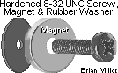 Detectable Steel Target/Trigger
Screw w/Magnet and Protective Rubber Washer for Custom Flywheel-Triggered
Electronic Ignition Systems. Head of screw becomes magnetized. Fasten on
rotating disc, edge of flywheel or backside of flywheel (in the case of an
Onan engine) when using a 3-wire hall effect proximity sensor or hall effect
electronic ignition sensor/module to trigger the spark. 8-32 UNC x 1/2" length
hardened steel Phillips head screw.
Click/tap here to learn
how to professionally cut new threads. Weighs about 1/10 oz. / 2 grams.
NOTE: The rubber washer prevents the high strength but delicate and brittle
magnet from possibly breaking when the screw is tightened to the uneven or
rough casting on the flywheel. IMPORTANT: To prevent from possibly loosening,
secure screw in flywheel or rotating disc with
high strength liquid threadlocker
(Red Loctite, Permatex or equivalent). Tighten
screw just when the rubber begin to bulge, and allow the Loctite to dry and
harden overnight. The hall effect electronic ignition sensor/module is activated
by the South pole of the magnet, so do not remove the magnet from the screw!
$10.00 each, plus shipping & handling.
Detectable Steel Target/Trigger
Screw w/Magnet and Protective Rubber Washer for Custom Flywheel-Triggered
Electronic Ignition Systems. Head of screw becomes magnetized. Fasten on
rotating disc, edge of flywheel or backside of flywheel (in the case of an
Onan engine) when using a 3-wire hall effect proximity sensor or hall effect
electronic ignition sensor/module to trigger the spark. 8-32 UNC x 1/2" length
hardened steel Phillips head screw.
Click/tap here to learn
how to professionally cut new threads. Weighs about 1/10 oz. / 2 grams.
NOTE: The rubber washer prevents the high strength but delicate and brittle
magnet from possibly breaking when the screw is tightened to the uneven or
rough casting on the flywheel. IMPORTANT: To prevent from possibly loosening,
secure screw in flywheel or rotating disc with
high strength liquid threadlocker
(Red Loctite, Permatex or equivalent). Tighten
screw just when the rubber begin to bulge, and allow the Loctite to dry and
harden overnight. The hall effect electronic ignition sensor/module is activated
by the South pole of the magnet, so do not remove the magnet from the screw!
$10.00 each, plus shipping & handling.
Click here to contact A-1 Miller's Performance Enterprises to place an order, send your parts for repairing, and/or for FREE professional and honest technical customer service assistance and support and payment options. If you need a part or parts that's not listed in this website, please contact A-1 Miller's and we'll see if we can get it at a reasonable price. | [Return to previous paragraph, section or website] [Top of Page]
Information About Kohler's Breakerless Ignition - (Scroll down for more information on this.)

If a Kohler flywheel has no projection (slightly angled hump) or large bolt head for Breakerless Ignition, but does have the 3/4" wide area between the fins and ring gear, or a billet steel flywheel, to use a magnetic pickup coil, 3-wire inductive (detects iron/steel) proximity sensor, a small, short steel Phillips or button head socket (Allen) Head screw and a minimum 1/4" length aluminum spacer secured with a split lock washer or high strength liquid threadlocker (Red Loctite, Permatex or equivalent) can be used as the signal detection for the flywheel-triggered electronic ignition. A steel dowel pin or knurled steel pin could be used instead of a screw or spiral pin, but because of exerted centrifugal force, the screw would be more secure due to its thread retention. FYI - Store a container of liquid threadlocker or Super Glue upright and not laying flat. The capped tip will not dry out and clog when stored upright.
The curvature or dome shaped heads of button- and Phillips-head screws makes them ideal for use on a trigger disc or flywheel. Spark occurs at the leading (high side) edge of the hump or screw, and not in the center of the hump or screw. When the magnetic pickup coil or cube-shaped proximity sensor is at the leading edge of the hump and when the S mark on the flywheel is aligned with the raised line on the bearing plate, it is at this point the timing is at 20º BTDC. But if the flywheel has the 3/4" wide area, but no projection (hump) or large bolt head, with the magnetic pickup coil or cube-shaped proximity sensor installed on the bearing plate and the 20º BTDC mark on the flywheel aligned with the raised line on the bearing plate.
When using an inductive proximity sensor, being proximity sensors detect a farther distance (up to 3/16") than a magnetic pickup coil, install a 3/4" length steel screw with a 1/4" length aluminum spacer (to retain flywheel balance). This will extend the detectable target 1/4" above the surface of the flywheel to prevent an out of time spark occurrence by part of the flywheel itself. Or if using a non-magnetic pickup coil, 3-wire hall effect proximity sensor or a non-magnetic electronic ignition sensor/module, a small ring magnet fastened by a small screw can be used to create a rotating magnet detection target. The head of the screw will become magnetized.
An 8-32 UNC and 10-32 UNF x 1/2" length screws with a split lock washer (and small magnet) only weighs about 1/10 of an ounce or 2.8 grams, so this will not make the flywheel significantly noticeably or dangerously out of balance. But if you're concerned about the flywheel being out of balance with the trigger screw/bolt, pin or screw w/ring magnet installed, the flywheel can be static balanced by weighing the flywheel and screw/bolt, pin or screw w/ring magnet separately on a precision scale, make a note of the exact weight of each item, and either install a stainless steel screw of the same exact weight as the trigger screw and magnet on the opposite side of the flywheel (180º apart), or drill a couple of shallow holes into the flywheel next to or beside the installed trigger screw/bolt, pin or screw w/ring magnet to put the flywheel back in balance. Make sure the flywheel is absolutely clean of dirt and debris, too. Actually, it's best to have the flywheel with the trigger screw/bolt, pin or screw w/ring magnet installed dynamically precision spin-balanced on a automotive balancing machine. Again, make sure the flywheel is absolutely clean of dirt and debris.
And for the ignition timing to be set at 20º BTDC, with the
S mark on the flywheel and raised line on the bearing plate
aligned, the screw will need to be located at 2-3/8" when using a magnetic
pickup coil or proximity sensor. This setup can be adapted to a Kohler engine
with the flywheel that has the starter/generator and gear starter alike.
Or it can be applied to an engine with a steel flywheel for competition pulling.
And the mounting holes in the angled bracket for the magnetic pickup coil
can be elongated for precise adjustment/setting of the timing.
If there's already a projection (hump) or
large bolt head on the flywheel, then there's no need to modify the flywheel
for this conversion or upgrade. If they're not already present, new 10-24
UNC threads will need to be
drilled
and tapped in the two raised bosses
in the bearing plate to mount the bracket for the sensor's bracket.
An original, ingenious, thoroughly researched and innovative concept invented
by A-1 Miller's, because nobody else advertise this for use on a small engine.
Please do not accept advertised copycat products of this kind. (But I do
appreciate them acknowledging my ingenuity and intelligence.)
Information About Converting from a Failed OEM Kohler Breakerless Ignition System to a Custom-Made Battery-Powered Electronic Ignition System or Battery-Powered Points/Condenser Ignition System | [Top of Page]
The energizer wire that
come from the stator under the flywheel for Kohler Breakerless Ignition or
Tecumseh Solid State Electronic Ignition Module generates about 250 volts
(serious) while the engine is running at full governed speed. Actually, the
primary circuit in virtually all magneto ignition coils generate anywhere
from 200 to 400 volts. So do not touch this wire or terminal with one bare
hand and the engine itself with your other bare hand while the engine is
running! Electrocution or death could occur. It is not needed for any of
A-1 Miller's crank-trigger ignition systems. So snip off this wire or tape
up the terminal.
 NOTE: On all Kohler engines
with Breakerless Ignition, there is a tiny (3/16") brass cup/expansion cup
plug in the points pushrod hole. This is to prevent oil from leaking out
the crankcase with Breakerless Ignition. This plug MUST be removed to use
the points pushrod when converting to points/condenser ignition. To prevent
damage to certain moving parts inside the engine and possible eventual internal
engine failure, do not push this plug into the crankcase! It may NOT drain
out with the oil either. If it is pushed into the crankcase, the oil pan
will need to be removed in order to remove the brass plug. To remove this
plug from outside the engine, carefully and gently drill a 7/64" pilot
hole through the plug, then use a #6
self-tapping drywall screw (a small
ordinary self-tapping screw may not work as well) with
small Vise-Grips or a small
crowbar or
pry bar hooked to the screw to pull the plug out of the
hole. Because without drilling the hole first, the self-tapping drywall screw
by itself may not be able to bore a hole through the plug without pushing
it deeper into the pushrod hole. And do not force the drill bit into the
plug or it could get pushed inside the crankcase! Use a new drill bit if
necessary. When the plug is removed, a 3/16" drill bit or hand reamer may
need to be used to clean out any debris/rust from the pushrod hole. After
the points is properly installed, and with the piston positioned at TDC on
the compression stroke, set the point gap at .020", or better yet,
set the ignition timing at 20º
BTDC, and definitely use a copper core/non-resistor spark plug of the
correct type gapped at .035".
NOTE: On all Kohler engines
with Breakerless Ignition, there is a tiny (3/16") brass cup/expansion cup
plug in the points pushrod hole. This is to prevent oil from leaking out
the crankcase with Breakerless Ignition. This plug MUST be removed to use
the points pushrod when converting to points/condenser ignition. To prevent
damage to certain moving parts inside the engine and possible eventual internal
engine failure, do not push this plug into the crankcase! It may NOT drain
out with the oil either. If it is pushed into the crankcase, the oil pan
will need to be removed in order to remove the brass plug. To remove this
plug from outside the engine, carefully and gently drill a 7/64" pilot
hole through the plug, then use a #6
self-tapping drywall screw (a small
ordinary self-tapping screw may not work as well) with
small Vise-Grips or a small
crowbar or
pry bar hooked to the screw to pull the plug out of the
hole. Because without drilling the hole first, the self-tapping drywall screw
by itself may not be able to bore a hole through the plug without pushing
it deeper into the pushrod hole. And do not force the drill bit into the
plug or it could get pushed inside the crankcase! Use a new drill bit if
necessary. When the plug is removed, a 3/16" drill bit or hand reamer may
need to be used to clean out any debris/rust from the pushrod hole. After
the points is properly installed, and with the piston positioned at TDC on
the compression stroke, set the point gap at .020", or better yet,
set the ignition timing at 20º
BTDC, and definitely use a copper core/non-resistor spark plug of the
correct type gapped at .035".
| Custom-Made Electronic Ignition Kits (below) for Converting
Kohler engine models K241, K301, K321, K341 or K361 to Flywheel-Triggered
Ignition, if the engine originally came with points/condenser ignition or
Breakerless Ignition. Do away with the old fashioned points and condenser
ignition, or defective and cost-prohibitive Breakerless Ignition components,
and convert your engine to the reliability, dependability and durability
of flywheel-triggered ignition!
This ignition system operates with full 12 volts. This is a thoroughly
tested, researched and proven reliable ignition system invented by A-1 Miller's
for ordinary lawn & garden engines and competition pulling engines. With
most tractors, the ignition conversion can be made with the engine in the
tractor. The only modifications that need to be done is the flywheel shroud
needs to be loosened to access and replace the Trigger Module, and two holes
will need to be drilled and tapped with the 2 supplied screws in the kit.
To install this replacement ignition system; the ignition coil mounts in
place of the Breakerless Ignition coil; the proximity cube sensor/bracket
mounts in place of the Breakerless Ignition Trigger Module, which is located
at the 10:30 position on the bearing plate; and two 9/64" holes will need
to be drilled and tapped (with the two self-threading screws are supplied
with the kit) on the backside of the bearing plate, on the left side when
facing the flywheel, to mount the GM HEI ignition control module. Be sure
to install small flat washers between the module and mounting surface to
provide an "air space" so the module will remain cool while in
operation.
IMPORTANT: Most failures of battery-powered ignition coils and/or electronic ignition control modules are caused by either the use of suppression/carbon-core spark plug wire(s), resistor-type spark plug(s), or overcharging of the electrical system due to a defective voltage rectifier/regulator or defective [automotive] battery. Therefore, if it's not already equipped, it's best to install an ammeter/amp gauge to monitor the charging system. Also, the coil and module may burn up if the ignition switch is left on for more than a few minutes with the engine not running. To prevent this from possibly happening and/or for security reasons, use an OFF-ON key switch and/or a master disconnect switch with a removable key instead of just a toggle switch to power the ignition system. Also, the coil could burn up if the charging system continually overcharge due to a defective voltage rectifier/regulator or a defective [automotive] battery. List of Parts in Kit Includes:
Installation Instructions: Click/tap here to print out the wiring diagram and installation/wiring connection instructions.
Wiring Diagram and Wiring Connection Instructions:
I offer the Option #1 kits below. Please let me know which kit you'd prefer and I'll give you the total amount with shipping and payment options. Click here to contact A-1 Miller's for FREE honest and accurate technical support and/or for ordering information and payment options. Please contact A-1 Miller's if you need part(s) and/or service(s) performed that's not listed or mentioned in this website. [Top of Page] To convert from Breakerless Ignition to Points and Condenser Ignition System. NOTE: New 12 volt ignition coil and spark plug wire included with each kit below.
To Convert from Points and Condenser Ignition to A-1 Miller's Custom Electronic Ignition System. NOTE: Your 12 volt ignition coil and spark plug wire can be reused with each option below.
To Convert from Breakerless Ignition to A-1 Miller's Custom Electronic Ignition System. NOTE: With points and condenser ignition, your 12 volt ignition coil and spark plug wire is to be reused with each kit below.
Option #2 - A-1 Miller's Custom-Made Reliable and Maintenance-Free 12 Volt Electronic Ignition Conversion Kit that is Triggered Off the Ring Gear of a 9-1/2" Flywheel with the Narrow, Tapered Edge. (Most common type of flywheel.) Convert from points and condenser ignition to electronic ignition on Kohler Engine Models K241, K301, K321, K341 and K361. Invented by A-1 Miller's. Please do not accept an advertised copycat product of this kind. (Copywrite infringement.) [Top of Page]
Installation Instructions: Click/tap here to print out the wiring diagram and installation/wiring connection instructions.
Option #3 - Complete Battery-Powered Points and Condenser Ignition System Kit to Convert from [a failed] OEM Kohler Breakerless Ignition OR a Cast Iron Block Briggs & Stratton Engine with a Magneto Ignition System. Designed for Kohler engine models K181, K241, K301, K321 (that originally came with Breakerless Ignition).
Ignition Parts Include: (Prices are as of 2/7/25)
NOTE - Being this ignition system requires 12 volts DC negative ground of power, the OEM key switch for Breakerless Ignition will not work with any battery-powered ignition systems. The switch used with Breakerless Ignition is actually a magneto ignition switch, which when the engine is shut-down, it grounds the self-energizing wire connected to the ignition. And battery ignition requires a switch that disconnects the coil from the power source (battery). So with A-1 Miller's ignition system, you will need either a battery type OFF-ON-START key switch, or an OFF-ON toggle switch or an OFF-ON rotary key switch (for security purposes) and a momentary push button starter switch. Go here for choice of switches. IMPORTANT: Most failures of a battery-powered ignition coils and/or electronic ignition control modules are caused by either the use of suppression/carbon-core spark plug wire(s), resistor-type spark plug(s), or overcharging of the electrical system due to a defective voltage rectifier/regulator or defective [automotive] battery. Therefore, if it's not already equipped, it's best to install an ammeter/amp gauge to monitor the charging system. Also, any coil will burn up if the ignition switch is left on with the points closed for more than a few minutes with the engine not running. To prevent this from possibly happening and/or for security reasons, use an OFF-ON key switch and/or a master disconnect switch with a removable key instead of just a toggle switch to power the ignition system. Also, the coil could burn up if the charging system continually overcharge due to a defective voltage rectifier/regulator or a defective [automotive] battery.
|
|||
Click here to contact A-1 Miller's Performance Enterprises to place an order, send your parts for repairing, and/or for FREE professional and honest technical customer service assistance and support and payment options. If you need a part or parts that's not listed in this website, please contact A-1 Miller's and we'll see if we can get it at a reasonable price. | [Return to previous paragraph, section or website] [Top of Page]
3/16" Steel Plug for Kohler Ignition Points Pushrod
Hole. Fits Kohler engine models K90/K91, K141, K160/K161,
KV161,
L160/L161, L181,
K181, K241, K301, K321, K341, K361, and K482, K532, K582 (with an unworn
points pushrod hole). Use this part (to prevent eventual oil leakage) when
converting engine to electronic ignition. (Listed in this website.) Remove
points cover, points and OEM pushrod, and install this plug in the pushrod
hole with a medium size hammer. Plug should fit tight in hole, but if it
fits loose, create knurled/raised ridges on the plug with a sharp, flat cold
chisel and hammer, and apply silicone sealant on plug when installing in
the block. No need to reinstall cover and points. NOTE: The alternative
to using this plug is to remove the ignition points and points pushrod, and
place the pushrod on a hard, flat surface, and use a hammer and sharp flat
cold chisel to lightly create knurled raised marks midway on the pushrod.
Then reinstall the knurled pushrod in the engine block with the hammer. Or
a
20 penny common nail cut off to 1/2" length and the end
ground to a bevel will serve the same purpose. The knurled ridges will retain
the pushrod in the hole. Replaces Kohler part # X-702-1 (brass welch
plug). OEM Briggs & Stratton part #'s 231143, 692882. $6.00 each,
plus shipping & handling. [Return
to previous paragraph, section or website]
 Points Pushrod Hole Block-Off
Plate. Fits Kohler engine models K90/K91, K141, K160/K161,
KV161,
L160/L161, L181,
K181, K241, K301, K321, K341, K361, KT17 (first design), KT17 Series II,
KT19 (first design) KT19 Series II, KT21, K482, K532 and K582. Use this part
to cover points pushrod hole when converting engine to electronic ignition.
(Listed in this website.) Apply RTV silicone sealant to prevent oil leak
and use the OEM ignition points mounting screws to secure plate in place.
An ingenious and innovative concept by A-1 Miller's. Please do not accept
advertised copycat products of this kind. (But I do appreciate them acknowledging
my ingenuity and intelligence.)
A-1 Miller's fabricated part. $10.00 each, plus shipping & handling.
Points Pushrod Hole Block-Off
Plate. Fits Kohler engine models K90/K91, K141, K160/K161,
KV161,
L160/L161, L181,
K181, K241, K301, K321, K341, K361, KT17 (first design), KT17 Series II,
KT19 (first design) KT19 Series II, KT21, K482, K532 and K582. Use this part
to cover points pushrod hole when converting engine to electronic ignition.
(Listed in this website.) Apply RTV silicone sealant to prevent oil leak
and use the OEM ignition points mounting screws to secure plate in place.
An ingenious and innovative concept by A-1 Miller's. Please do not accept
advertised copycat products of this kind. (But I do appreciate them acknowledging
my ingenuity and intelligence.)
A-1 Miller's fabricated part. $10.00 each, plus shipping & handling.
A-1 Miller's Custom-Made Flywheel-Triggered Electronic Ignition Conversion Kit for Kohler opposed twin cylinder engine models KT17 (first design), KT17 Series II, KT19 (first design), KT19 Series II, KT21, and perhaps opposed twin cylinder Magnum engines with the KT-series flywheel installed, except generator engines. [Top of Page]
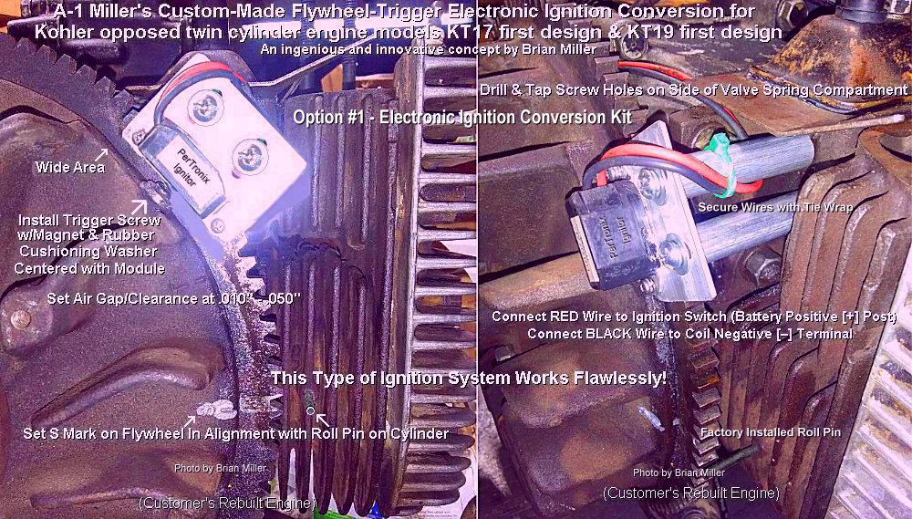
Designed
to convert a 12 volt points and condenser ignition system into the more reliable
and dependable 100% digital 12 volt electronic ignition system.
Points and condenser cannot be used with this ignition system. Remove the
points and condenser and cover the points pushrod hole with the supplied
block-off plate with silicone sealant. With this custom electronic ignition
conversion kit, the edge of the flywheel must be drilled and tapped with
installation for a small screw and magnet. This type of electronic ignition
must be triggered off the flywheel. There is no other way of making it happen.
If you can't find someone local that can do this for you,
A-1 Miller's offer this service if you won't mind bringing
your engine to us. Invented by A-1 Miller's. Please do not accept an
advertised copycat product of this kind.
(Copywrite infringement.)
This high-performance ignition system have been thoroughly tested under extreme conditions, and produces a stable and a very strong spark with the use of microelectronics, even with the stock OEM canister ignition coil, helping the engine to start quicker, idle smoothly and rev up to full RPM with no hesitation whatsoever. The OEM Kohler [4.0 ohm] opposed twin cylinder canister ignition coil works excellent with this ignition sensor/module to produce a a very strong spark. Turns the stock coil into a high-performance coil without shortening the life of the coil. This revolutionizes the ignition system for the opposed twin cylinder Kohler engines! With points (and condenser) ignition, the factory setting for the timing on these engines is 23º BTDC. Being the points is operated off the camshaft, and being there's slight free-play/clearance between the gear teeth on the camshaft and crankshaft (which is normal), the ignition timing can fluctuate a few degrees, resulting in slight loss of engine power. And sometimes the lobe for the points pushrod on the cam will wear, which will make setting the timing at full 23º BTDC impossible, which will also cause the engine to lose power. (Both of these are confirmed in the official Kohler KT17, KT17 Series II, KT19 and KT19 Series II service manual.) And with a worn points lobe, the entire engine will need to be completely disassembled to replace the camshaft. This custom-made electronic ignition system maintains the timing at 23º BTDC at all times because it operates off the flywheel, which is driven by the crankshaft. With this custom ignition system, the timing will never change. It works the same as crank trigger ignition. To prevent burning up the electronic ignition module, it MUST be used with a coil having a minimum of 3.0 ohm resistance, and a sturdy, fabricated bracket to prevent timing fluctuations.
KT-series Electronic Ignition Option #1 - This electronic ignition conversion kit use two round supports that fastens on the side of the valve spring compartment, to mount the module/sensor onto. (Pictured above.) This kit is designed specifically for the KT17 (first design), KT19 (first design) and KT21 engines. But can also be used on the KT17 Series II and KT19 Series II engines, and Magnum opposed twin cylinder engines with the KT-series flywheel installed. Kit includes: New hall effect electronic ignition sensor/module fastened on adjustable/slotted aluminum mounting plate, two 10-24 UNC screws w/flat washers and lock washers, two aluminum spacers, target screw w/magnet and rubber washer (prevents the delicate rare earth magnet from possibly breaking when lightly fastened against the uneven rough casting of the flywheel), two new Autolite 26 or Champion 25 (RV17YC) spark plugs, and points pushrod hole block-off plate (use with silicone sealant). Use this ignition system with the OEM off-ignition-start key switch and dual wire ignition coil. All replacement ignition parts are readily available. And if this custom electronic ignition is used in a garden tractor with a longitudinal engine, such as Cub Cadet, Economy Power King, Ford, hydrostatic-drive John Deere, MTD Farm King Model 960, Pennsylvania Panzer, Meteor, Copar, etc., it'll be easier to install if the engine is removed from the tractor. NOTE: If your engine is hard to start, looses horsepower and dies when hot, and restarts when cooled, and repeats this over and over, then chances are, it needs a professional valve job performed with the valve clearances reset to factory specs. Because just installing electronic ignition will not fix a faulty valve problem. Please contact A-1 Miller's if you're interested in having a professional valve job performed on your Kohler opposed twin cylinder engine.
INSTALLATION INSTRUCTIONS for KT17 (first design), KT19 (first design) and KT21 engines. This option can also be used on the KT17 Series II and KT19 Series II engines, and Magnum opposed twin cylinder engines with the KT-series flywheel installed. Video of this ignition system installed on a running engine coming later. Scroll down to read the wiring connection instructions or click here to view and print out these installation instructions.
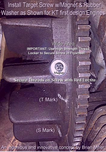
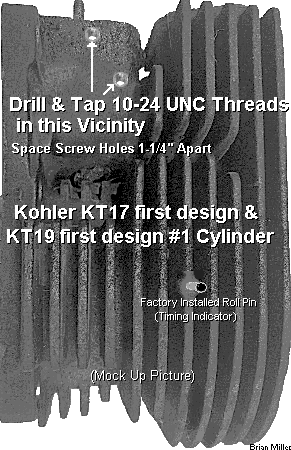 Use a
Sharpie metallic silver permanent ink marker to locate
and install the trigger screw
w/magnet and rubber washer on the flat area on the flywheel above the
T mark as shown in the photo to the right ->. This will place the
ignition timing in alignment with the center of the electronic ignition
sensor/module when the S mark on the flywheel is in exact alignment
with the roll pin on the cylinder (which is positioned at 23º BTDC).
The screw head in the magnet is magnetized to trigger the spark. There is
no need to remove the flywheel to drill and tap the threads to accept the
supplied 6-32 UNC trigger screw.
Click/tap here to learn
how to professionally cut new threads. To prevent from possibly breaking
off drill bit or tap, secure the flywheel so it does not rotate one way or
the other while drilling hole and/or cutting threads! NOTE: The rubber
washer prevents the delicate rare earth magnet from possibly breaking when
lightly fastened against the uneven rough casting of the flywheel. IMPORTANT:
To prevent from possibly loosening, secure screw in flywheel or rotating
disc with
high strength liquid threadlocker
(Red Loctite, Permatex or equivalent). Tighten
screw just when the rubber begin to bulge, and allow the Loctite to dry and
harden overnight. The hall effect electronic ignition sensor/module is activated
by the South pole of the magnet, so do not remove the magnet from the screw!
FYI - Store a container of liquid threadlocker or Super Glue upright and
not laying flat. The capped tip will not dry out and clog when stored
upright.
Being there are no two bosses
on the cooling fins of the #1 cylinder (right side of engine when facing
the flywheel) of the KT17 (first design) and KT19 (first design) engines,
use the flat casting on the side of the valve spring compartment on the #1
cylinder facing the flywheel to mount the two supports with the electronic
ignition sensor/module adjustable mounting plate. See the
[mock up] photo in this section.
Use a
Sharpie metallic silver permanent ink marker to locate
and install the trigger screw
w/magnet and rubber washer on the flat area on the flywheel above the
T mark as shown in the photo to the right ->. This will place the
ignition timing in alignment with the center of the electronic ignition
sensor/module when the S mark on the flywheel is in exact alignment
with the roll pin on the cylinder (which is positioned at 23º BTDC).
The screw head in the magnet is magnetized to trigger the spark. There is
no need to remove the flywheel to drill and tap the threads to accept the
supplied 6-32 UNC trigger screw.
Click/tap here to learn
how to professionally cut new threads. To prevent from possibly breaking
off drill bit or tap, secure the flywheel so it does not rotate one way or
the other while drilling hole and/or cutting threads! NOTE: The rubber
washer prevents the delicate rare earth magnet from possibly breaking when
lightly fastened against the uneven rough casting of the flywheel. IMPORTANT:
To prevent from possibly loosening, secure screw in flywheel or rotating
disc with
high strength liquid threadlocker
(Red Loctite, Permatex or equivalent). Tighten
screw just when the rubber begin to bulge, and allow the Loctite to dry and
harden overnight. The hall effect electronic ignition sensor/module is activated
by the South pole of the magnet, so do not remove the magnet from the screw!
FYI - Store a container of liquid threadlocker or Super Glue upright and
not laying flat. The capped tip will not dry out and clog when stored
upright.
Being there are no two bosses
on the cooling fins of the #1 cylinder (right side of engine when facing
the flywheel) of the KT17 (first design) and KT19 (first design) engines,
use the flat casting on the side of the valve spring compartment on the #1
cylinder facing the flywheel to mount the two supports with the electronic
ignition sensor/module adjustable mounting plate. See the
[mock up] photo in this section.
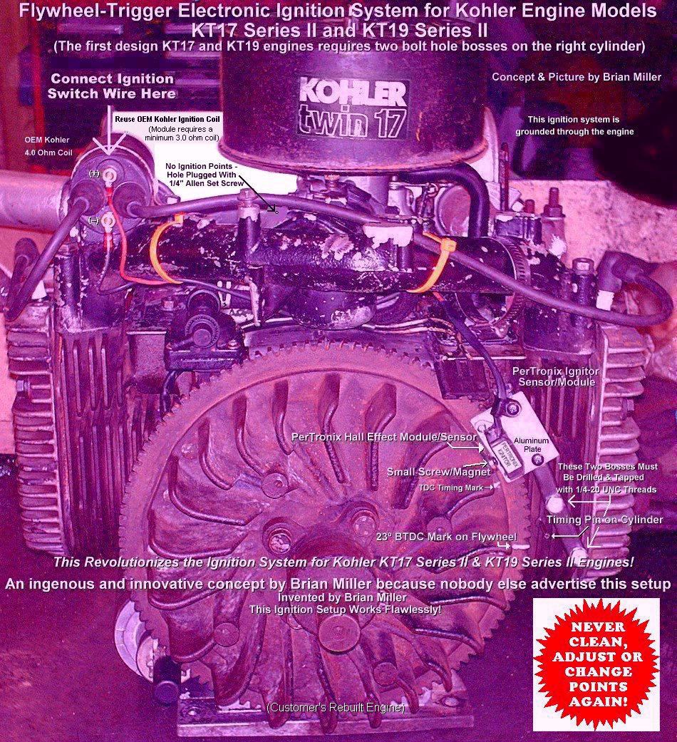
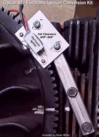 KT-series Electronic Ignition
Option #2 - This electronic ignition conversion kit use a somewhat long square
steel tube support that mounts on the 2 bosses on the #1 cylinder, to mount
the module/sensor onto. (Pictured above.) This kit is specifically designed
ONLY for the KT17 Series II and KT19 Series II engines (and perhaps Magnum
engines with the KT-series flywheel installed). Kit includes: New hall effect
electronic ignition sensor/module fastened on aluminum mounting plate and
square steel tubing, two 1/4" x 1-1/2" length grade 8 bolts w/lock washers,
target screw w/magnet and rubber washer (prevents the delicate rare earth
magnet from possibly breaking when lightly fastened against the uneven rough
casting of the flywheel), two Autolite 26 or Champion 25 (RV17YC) spark
plugs, and points pushrod hole block-off plate (use with silicone sealant).
Use this ignition system with the OEM off-ignition-start key switch and dual
wire ignition coil. All replacement ignition parts are readily available.
And if this custom electronic ignition is used in a garden tractor with a
longitudinal engine, such as Cub Cadet, Economy Power King,
Ford, hydrostatic-drive John Deere, MTD Farm King Model 960, Pennsylvania
Panzer, Meteor, Copar, etc., it'll be easier to install if the engine is
removed from the tractor.
KT-series Electronic Ignition
Option #2 - This electronic ignition conversion kit use a somewhat long square
steel tube support that mounts on the 2 bosses on the #1 cylinder, to mount
the module/sensor onto. (Pictured above.) This kit is specifically designed
ONLY for the KT17 Series II and KT19 Series II engines (and perhaps Magnum
engines with the KT-series flywheel installed). Kit includes: New hall effect
electronic ignition sensor/module fastened on aluminum mounting plate and
square steel tubing, two 1/4" x 1-1/2" length grade 8 bolts w/lock washers,
target screw w/magnet and rubber washer (prevents the delicate rare earth
magnet from possibly breaking when lightly fastened against the uneven rough
casting of the flywheel), two Autolite 26 or Champion 25 (RV17YC) spark
plugs, and points pushrod hole block-off plate (use with silicone sealant).
Use this ignition system with the OEM off-ignition-start key switch and dual
wire ignition coil. All replacement ignition parts are readily available.
And if this custom electronic ignition is used in a garden tractor with a
longitudinal engine, such as Cub Cadet, Economy Power King,
Ford, hydrostatic-drive John Deere, MTD Farm King Model 960, Pennsylvania
Panzer, Meteor, Copar, etc., it'll be easier to install if the engine is
removed from the tractor.
With this custom electronic ignition conversion kit, the edge of the flywheel must be drilled and tapped with installation for a small screw and magnet. This type of electronic ignition must be triggered off the flywheel. There is no other way of making it happen. If you can't find someone local that can do this for you, A-1 Miller's offer this service if you won't mind bringing your engine to us. Invented by A-1 Miller's. Please do not accept an advertised copycat product of this kind. (Copywrite infringement.)
INSTALLATION INSTRUCTIONS of the sensor/module specifically for KT17 Series II and KT19 Series II engines, (and perhaps Magnum engines with the KT-series flywheel installed) - Video of this ignition system installed on a running engine coming later.
trigger screw
w/magnet and rubber washer on the flat area on the flywheel above the
T mark as shown in the photo to the right ->. This will place the
ignition timing in alignment with the center of the self-contained electronic
ignition sensor/module when the S mark on the flywheel is in
exact alignment with the roll pin on the cylinder (which is positioned at
23º BTDC). The screw head is magnetized to trigger the spark. There
is no need to remove the flywheel to drill and tap the threads. The screw
hole must be professionally drilled and tapped to accept the supplied 6-32
UNC trigger screw. Click
here to learn how to professionally cut new threads. To prevent breaking
off drill bit or tap, secure the flywheel so it does not rotate one way or
the other while drilling hole and/or cutting threads! NOTE: The rubber
washer prevents the delicate rare earth magnet from possibly breaking when
lightly fastened against the uneven rough casting of the flywheel. IMPORTANT:
To prevent from possibly loosening, secure screw in flywheel or rotating
disc with
high strength liquid threadlocker
(Red Loctite, Permatex or equivalent). Tighten
screw just when the rubber begin to bulge, and allow the Loctite to dry and
harden overnight. The hall effect electronic ignition sensor/module is activated
by the South pole of the magnet, so do not remove the magnet from the screw!
FYI - Store a container of liquid threadlocker or Super Glue upright and
not laying flat. The capped tip will not dry out and clog when stored
upright.
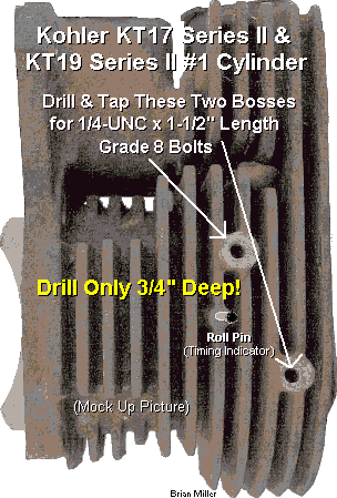 Use the two bosses on the #1 cylinder to mount the bracket
with the ignition sensor/module. Being there are no bolt holes in the bosses,
the center of each boss must be professionally drilled and tapped to accept
the supplied 1/4-20 UNC x 1-1/2" length grade 8 bolts with split lock washers.
Click/tap here to learn
how to professionally cut new threads.
IMPORTANT! Drill only 3/4" deep; do not drill
all the way through the cylinder wall! To guarantee the 3/4" depth, use a
Use the two bosses on the #1 cylinder to mount the bracket
with the ignition sensor/module. Being there are no bolt holes in the bosses,
the center of each boss must be professionally drilled and tapped to accept
the supplied 1/4-20 UNC x 1-1/2" length grade 8 bolts with split lock washers.
Click/tap here to learn
how to professionally cut new threads.
IMPORTANT! Drill only 3/4" deep; do not drill
all the way through the cylinder wall! To guarantee the 3/4" depth, use a
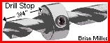 drill stop (small set screw collar) secured at the 3/4"
depth. There is no need to remove the flywheel to do this.
See the
[mock up] animated photo to the right.->
drill stop (small set screw collar) secured at the 3/4"
depth. There is no need to remove the flywheel to do this.
See the
[mock up] animated photo to the right.->
Detectable Steel Target Screw w/Magnet and Protective Rubber
Washer for Custom Flywheel-Triggered Electronic Ignition Systems. Head of
screw becomes magnetized. Fasten on rotating disc, edge of flywheel or backside
of flywheel (in the case of an Onan engine) when using a 3-wire hall effect
proximity sensor or hall effect electronic ignition sensor/module to trigger
the spark. 8-32 UNC x 1/2" length hardened steel Phillips head screw.
Click/tap here to learn
how to professionally cut new threads. Weighs about 1/10 oz. / 2 grams.
NOTE: The rubber washer prevents the high strength but delicate and brittle
magnet from possibly breaking when the screw is tightened to the uneven or
rough casting on the flywheel. IMPORTANT: To prevent from possibly loosening,
secure screw in flywheel or rotating disc with
high strength liquid threadlocker
(Red Loctite, Permatex or equivalent). Tighten
screw just when the rubber begin to bulge, and allow the Loctite to dry and
harden overnight. The hall effect electronic ignition sensor/module is activated
by the South pole of the magnet, so do not remove the magnet from the
screw! $10.00 each, plus shipping & handling. Please
let me know if you're interested in purchasing this
item and I'll give you the total amount with shipping and payment options.
Click here to contact A-1 Miller's Performance Enterprises to place an order, send your parts for repairing, and/or for FREE professional and honest technical customer service assistance and support and payment options. If you need a part or parts that's not listed in this website, please contact A-1 Miller's and we'll see if we can get it at a reasonable price. | [Return to previous paragraph, section or website] [Top of Page]
|
Custom-Made Reliable and Maintenance-Free 12 Volt Crank-Trigger Electronic Ignition Systems That Operate Off the PTO End of Virtually Any Older General-Use Small Engine or Competition Pulling Small Engine - Eliminates Old-Fashioned Points and Condenser or Troublesome OEM Solid State Ignition
Be
ahead of the pulling competition with 21st century technology using 100%
reliable digital electronic ignition!
Click here
to contact A-1 Miller's for FREE honest and accurate technical support and/or
for ordering information and payment options. Please contact A-1
Miller's
if you need part(s) and/or
service(s) performed that's not listed or mentioned in this
website. [Top of Page]
A new way to revolutionize the ignition system on virtually any small gas engine! Virtually trouble- and maintenance-free, and water-proof. These ignition modules/sensors is a small, lightweight, compact and completely self-contained electronic ignition system built with the latest state-of-the-art engineering with the use of microelectronics. Fits entirely on the engine block; no ignition box and additional wiring to clutter the engine compartment because the electronic ignition control module and pickup coil/sensor are contained in the same sealed casing. The self-contained Dynatek Dyna S sensor/module produce a stable and a very strong spark with the use of microelectronics. They will produce a stronger spark to help the engine to start quicker, idle smoothly and rev up to full RPM with no hesitation whatsoever. Allows a stock coil to perform like a high-performance coil without shortening the life of the coil.
These maintenance-free crank-trigger electronic ignition setups have been thoroughly tested and proven very reliable for general lawn and work, and all classes of single and opposed twin cylinder competition pulling engines. One sensor/module is needed for an opposed twin cylinder engine, and two modules/sensors spaced precisely at 90º apart are required for V-twin engines. These are the same ignition systems used by professional pullers everywhere. Reliable at high RPM, these electronic ignition modules provide unlimited RPM. They will allow the ignition system to operate at the speed of electricity (which can be anywhere from about 50% to 99% of the speed of light, depending upon the quality of the electronic components and wiring connections).
Spark occurs when the magnet embedded in an aluminum set screw collar (magnet ring), which is much like an automotive reluctor ring, that's fastened on the crankshaft's PTO end passes the sensor/module. These sensors/modules packs a lot of punch and allow the ignition system operate at 100% efficiency for a stronger spark. When wired correctly, it's normal for the flywheel- and crank-trigger ignition systems to make a spark when first powered up. And if it makes a spark as the sensor passes the metal target object, then the ignition system is working as it should.
NOTE: With all of my crank-trigger ignition systems (all listed below), when installed accordingly, the ignition timing is ALWAYS advanced. If it's set or installed retarded, it will NOT automatically advance as soon as the engine starts. If the timing is set retarded, the only way to advance it is by rotating an ignition plate or ignition distributor manually by hand, or automatically by a vacuum canister with intake manifold, or by centrifugal force with flyweights.
The Dynatek Dyna S sensor/module operates with 12-1/2 to 15 volts DC negative ground, and requires an ignition coil with a minimum 3.0 ohm resistor. Using a coil with less than 3.0 ohm of primary resistance for a long period of time will cause the module to overheat and the engine may misfire until it cools down, or the sensor/module might fail prematurely. A metal core spark plug wire and copper core/non-resistor spark plug should be used. If the voltage drops below the minimum requirement for either sensor/module, the engine may idle well, but not rev up, or the engine may run erratic. Either sensor/module can be used with a standard-output/stock or (40,000 volt) high-output/performance or OEM automotive electronic ignition coil, as long as it has a 3.0 ohm internal primary resistor, or connected to a ballast resistor, resulting in 3.0 ohm of resistance.
Maintenance-Free 12 Volt Dynatek Dyna S Crank-Trigger Electronic Ignition Installation Instructions -
 A-1 Miller's universal flat
aluminum mounting plate with the self-contained Dynatek Dyna S ignition
sensor/module kits can be adapted for use on various makes and models of
one or two cylinder (twin opposing cylinders) small engines. Being there
are so many different bolt patterns on the PTO end of Kohler and other makes
and models of small engines, these are not a simple "one kit fits all" bolt-on
ignition setup. Therefore, customer will need to locate and drill holes in
the mounting plate in alignment with the bolt holes on the PTO end of the
engine block. If there are no bolt hole(s) on the PTO end of the block, they
will need to be drilled and tapped.
Click/tap here to learn
how to professionally cut new threads. For strength and durability, a
minimum of 1/4" bolts (thread size) should be used to fasten mounting plate
to PTO end of engine block. Locate and drill (machine) slotted adjustment
holes in the mounting plate. And then drill and cut 4-40 NC threads in the
mounting plate to fasten the sensor/module. Air gap/clearance between the
sensor/module and set screw collar w/embedded magnet is .010" or .25mm -
.050" or 1mm. sensor/module may not operate or engine may misfire if gap
is wider than .060". NOTE: Do not allow sensor/module
to make contact with set screw collar w/embedded magnet while engine is
running! Click
HERE for custom-made electronic ignition
kits that operate off the flywheel end of the engine. These can be used for
ordinary lawn & garden engines or stock competition pulling
engines.
A-1 Miller's universal flat
aluminum mounting plate with the self-contained Dynatek Dyna S ignition
sensor/module kits can be adapted for use on various makes and models of
one or two cylinder (twin opposing cylinders) small engines. Being there
are so many different bolt patterns on the PTO end of Kohler and other makes
and models of small engines, these are not a simple "one kit fits all" bolt-on
ignition setup. Therefore, customer will need to locate and drill holes in
the mounting plate in alignment with the bolt holes on the PTO end of the
engine block. If there are no bolt hole(s) on the PTO end of the block, they
will need to be drilled and tapped.
Click/tap here to learn
how to professionally cut new threads. For strength and durability, a
minimum of 1/4" bolts (thread size) should be used to fasten mounting plate
to PTO end of engine block. Locate and drill (machine) slotted adjustment
holes in the mounting plate. And then drill and cut 4-40 NC threads in the
mounting plate to fasten the sensor/module. Air gap/clearance between the
sensor/module and set screw collar w/embedded magnet is .010" or .25mm -
.050" or 1mm. sensor/module may not operate or engine may misfire if gap
is wider than .060". NOTE: Do not allow sensor/module
to make contact with set screw collar w/embedded magnet while engine is
running! Click
HERE for custom-made electronic ignition
kits that operate off the flywheel end of the engine. These can be used for
ordinary lawn & garden engines or stock competition pulling
engines.
Dynatek Dyna S Crank Trigger Ignition Kit and Systems for a Single Cylinder Engine listed below. These ignition systems works flawlessly and may outlast the life of the engine. These ignition systems operate off the PTO end of the crankshaft and is mainly for competition pulling engines that have nothing on the PTO end of the crankshaft. NOTE: Slotted mounting holes will be machined in the mounting plate. If the bolt holes in the PTO end of the block don't match the ones in the plate or if bolt holes are not present, then new bolt holes will need to be drilled and tapped in the engine block. Click/tap here to learn how to professionally cut new threads. Can be used on Kohler 10-16hp single or opposed twin cylinder horizontal shaft engines. Set the clearance between the module and set screw collar at .010" or .25mm - .050" or 1mm. NOTE: For easier setting of the timing with the old style electronic ignition , use a permanent ink marker (Sharpie, Magic Marker, Marks-A-Lot, etc.) on the side of the collar in alignment with the magnet to indicate the location of the magnet. IMPORTANT - Gently rotate the flywheel back and forth by hand to check and see that the module does not make contact with the collar. Do not allow the module make contact with the collar while the engine is running! IMPORTANT - The module will burn up after a few minutes up if the ignition switch is left on with the engine not running. To prevent this from possibly happening and/or for security reasons, use an OFF-ON key switch and/or a master disconnect switch with a removable key instead of just a toggle switch to power the ignition system.
 Designed
to convert a 12 volt points and condenser ignition system into the more reliable
and dependable 100% digital 12 volt electronic ignition system.
Points and condenser cannot be used with this ignition system. Remove the
points and condenser and cover the points pushrod hole with the supplied
block-off plate with silicone sealant.
Designed
to convert a 12 volt points and condenser ignition system into the more reliable
and dependable 100% digital 12 volt electronic ignition system.
Points and condenser cannot be used with this ignition system. Remove the
points and condenser and cover the points pushrod hole with the supplied
block-off plate with silicone sealant.
Crank Trigger Ignition Kit with Dynatek Dyna S Sensor/Module Fastened on an Aluminum Mounting Plate, Triggered by an Embedded Magnet in a Set Screw Collar. Requires 12 volts DC negative ground of power and an ignition coil with minimum 3.0 ohms resistance. Mounting plate fastens on the PTO end of engine block, and coil mounts remotely on side of flywheel shroud or elsewhere in engine compartment. This high-performance ignition system have been thoroughly tested under extreme conditions, and produces a stable and a very strong spark with the use of microelectronics, helping the engine to start quicker, idle smoothly and rev up to full RPM with no hesitation whatsoever. Allows a stock coil to perform like a high-performance one without shortening the life of the coil. Ignition coil not included, customer use their own [minimum 3.0 ohm] ignition coil. Module may burn up if the wrong coil is used. Click here to learn how to test the ohm resistance of a coil.
Set the air gap/clearance between sensor and magnet in set screw collar at .010" or .25mm - .050" or 1mm, and set spark plug gap at .035".
NOTE: For easier setting of the timing with this electronic ignition module, use a permanent ink marker (Sharpie, Magic Marker, Marks-A-Lot, etc.) on the side of the set screw collar in alignment with the magnet to indicate the location of magnet.
Simple Wiring Connections: IMPORTANT - Connect the RED wire to the coil positive [+] terminal (which connects to the ignition switch and battery positive (+) post), and connect the BLACK wire to the coil negative (–) terminal. IMPORTANT: The module will burn up after a few minutes up if the ignition switch is left on with the engine not running. To prevent this from possibly happening and/or for security reasons, use an OFF-ON key switch and/or a master disconnect switch with a removable key instead of just a toggle switch to power the ignition system.
How to Install This Crank Trigger Ignition Kit and Set the Timing:
When the ignition unit is installed and wire(s) correctly connected, turn the ignition switch on to supply power to the coil, and rotate the flywheel back and forth by hand so the magnet passes the module and observe for a strong, audible "snappy" blue spark at the spark plug's tip. FYI - The blue color is made by burning of nitrogen and oxygen in the atmosphere when they are energized, and the snapping sound is breaking of the sound barrier, resulting in a very tiny sonic boom released from the rapid burning and explosion of the nitrogen and oxygen. Please specify diameter of crankshaft PTO end for set screw collar w/embedded magnet. Various OEM Kohler crankshaft PTO end diameters are 3/4", 1", 1-1/8", 1-1/4", 1-3/8", 1-7/16" and 1-1/2". Most billet steel crankshafts have a 1-1/2" diameter raised shoulder on the PTO end. Other sizes available. IMPORTANT: Use a new copper core/non-resistor AC Delco, Autolite or Champion spark plug of the correct type gapped at .025" for longer coil life. Use of a resistor type spark plug will void warranty. This ignition setup is shown above. Mounting plate available with 3-1/2" or 4" bolt hole spacing, but customer may have to drill and tap the block to mount the crank-trigger or modify the bracket if necessary. All replacement ignition parts are readily available. Video of this ignition system installed on a running engine coming later. $130.00 per kit, plus shipping & handling. Please let me know if you're interested in purchasing this kit and I'll give you the total amount with shipping and payment options.
Aluminum Set Screw collar
w/Embedded Trigger Magnet (Magnet Ring). Use with Dynatek Dyna S, hall
effect electronic ignition module, hall effect proximity sensors (listed
below) and/or digital tachometer
(with hall effect proximity sensor). When ordering, please specify diameter
of crankshaft PTO end or shaft it's to be mounted on. Most common Kohler
crankshaft PTO end diameters are 1", 1-1/8", but 3/4", 1-1/4", 1-3/8", 1-7/16"
and 1-1/2" are rare. Most billet steel crankshafts have a 1-1/2" diameter
PTO end (raised shoulder). NOTE: For easier setting of the timing with
the electronic ignition module, use a permanent ink marker
(Sharpie,
Magic Marker,
Marks-A-Lot, etc.) on the side of the set screw collar
in alignment with the magnet to indicate the location of the magnet. Other
sizes available. $30.00 each, plus shipping & handling. Please
let me know if you're interested in purchasing this
part and I'll give you the total amount with shipping and payment options.
[Return to previous section]
Points Pushrod Hole Block-Off
Plate. Fits Kohler engine models K90/K91, K141, K160/K161,
KV161,
L160/L161, L181,
K181, K241, K301, K321, K341, K361, KT17 (first design), KT17 Series II,
KT19 (first design) KT19 Series II, KT21, K482, K532 and K582. Use this part
to cover points pushrod hole when converting engine to electronic ignition.
(Listed in this website.) Apply RTV silicone sealant to prevent oil leak
and use the OEM ignition points mounting screws to secure plate in place.
A-1 Miller's fabricated part. $10.00 each, plus shipping & handling.
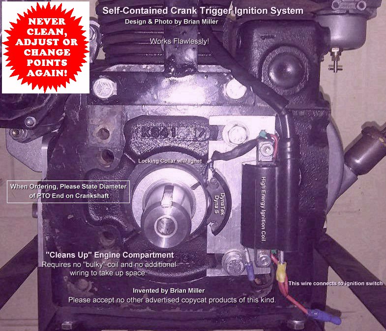 Designed
to convert a 12 volt points and condenser ignition system into the more reliable
and dependable 100% digital 12 volt electronic ignition system.
Points and condenser cannot be used with this ignition system. Remove the
points and condenser and cover the points pushrod hole with the supplied
block-off plate with silicone sealant.
Designed
to convert a 12 volt points and condenser ignition system into the more reliable
and dependable 100% digital 12 volt electronic ignition system.
Points and condenser cannot be used with this ignition system. Remove the
points and condenser and cover the points pushrod hole with the supplied
block-off plate with silicone sealant.
Complete Self-Contained and Compact Crank Trigger Ignition System Kit with Dynatek Dyna S Sensor/Module Incorporated with a High Energy Ignition Coil, Both Fastened on an Aluminum Mounting Plate, Triggered by an Embedded Magnet in a Set Screw collar. Requires 12 volts DC negative ground of power. Coil produces 20,000 volts. Thoroughly tested and proven to be very reliable. The high energy armature ignition coil is fastened above the Dynatek Dyna S sensor/module on the same aluminum ignition plate. This ignition system operates off the PTO end of the engine and is mainly for competition pulling engines that have nothing on the PTO end of the crankshaft. This ignition system "cleans up" the engine compartment. No remotely-mounted coil or extra wiring needed. Can be mounted above or on right side of crankshaft. This high-performance ignition system have been thoroughly tested under extreme conditions, and produces a stable and a very strong spark with the use of microelectronics, even with the compact epoxy-encapsulated armature ignition coil, helping the engine to start quicker, idle smoothly and rev up to full RPM with no hesitation whatsoever. The Dynatek Dyna S sensor/module is triggered by a small magnet embedded in an aluminum set screw collar (magnet ring) that's fastened on the crankshaft. All replacement ignition parts are readily available. Mounting plate available with 3-1/2" or 4" bolt hole spacing. But customer may have to drill and tap the block to mount the crank-trigger or modify the bracket if necessary. Click/tap here to learn how to professionally cut new threads. Invented by A-1 Miller's. Please do not accept an advertised copycat product of this kind. (Copywrite infringement.)
Simple Wiring Connections: Connect the RED wire to the ignition switch [which connects to the battery positive (+) post], and connect the BLACK wire to the grounding-type kill switch. The ignition system is grounded to the engine through negative (–) battery post. IMPORTANT: The module will burn up after a few minutes up if the ignition switch is left on with the engine not running. To prevent this from possibly happening and/or for security reasons, use an OFF-ON key switch and/or a master disconnect switch with a removable key instead of just a toggle switch to power the ignition system.
How to Install This Crank Trigger Ignition Kit and Set the Timing:
When the ignition unit is installed and wire(s) correctly connected, turn the ignition switch on to supply power to the coil, and rotate the flywheel back and forth by hand so the magnet passes the module and observe for a strong, audible "snappy" blue spark at the spark plug's tip. FYI - The blue color is made by burning of nitrogen and oxygen in the atmosphere when they are energized, and the snapping sound is breaking of the sound barrier, resulting in a very tiny sonic boom released from the rapid burning and explosion of the nitrogen and oxygen. The collar w/embedded magnet is available for all diameters of PTO end of the crankshaft. IMPORTANT: Use a new copper core/non-resistor AC Delco, Autolite or Champion spark plug of the correct type gapped at .025" for longer coil life. Use of a resistor type spark plug will void warranty. Please specify diameter of crankshaft PTO end for set screw collar w/embedded magnet. Various OEM Kohler crankshaft PTO end diameters are 3/4", 1", 1-1/8", 1-1/4", 1-3/8", 1-7/16" and 1-1/2". Most billet steel crankshafts have a 1-1/2" diameter raised shoulder on the PTO end. Other sizes available. $250.00 per kit, plus shipping & handling. Please let me know if you're interested in purchasing this kit and I'll give you the total amount with shipping and payment options.
Aluminum Set Screw collar
w/Embedded Trigger Magnet (Magnet Ring). Use with Dynatek Dyna S, hall
effect electronic ignition module, hall effect proximity sensors (listed
below) and/or digital tachometer
(with hall effect proximity sensor). When ordering, please specify diameter
of crankshaft PTO end or shaft it's to be mounted on. Various OEM Kohler
crankshaft PTO end diameters are 3/4", 1", 1-1/8", 1-1/4", 1-3/8", 1-7/16"
and 1-1/2". Most billet steel crankshafts have a 1-1/2" diameter raised shoulder
on the PTO end. Other sizes available. NOTE: For easier setting of the
timing with the electronic ignition module, use a permanent ink marker
(Sharpie,
Magic Marker,
Marks-A-Lot, etc.) on the side of the set screw collar
in alignment with the magnet to indicate the location of the magnet. Other
sizes available. $30.00 each, plus shipping & handling. Please
let me know if you're interested in purchasing this
part and I'll give you the total amount with shipping and payment options.
[Return to previous section]
Points Pushrod Hole Block-Off
Plate. Fits Kohler engine models K90/K91, K141, K160/K161,
KV161,
L160/L161, L181,
K181, K241, K301, K321, K341, K361, KT17 (first design), KT17 Series II,
KT19 (first design) KT19 Series II, KT21, K482, K532 and K582. Use this part
to cover points pushrod hole when converting engine to electronic ignition.
(Listed in this website.) Apply RTV silicone sealant to prevent oil leak
and use the OEM ignition points mounting screws to secure plate in place.
A-1 Miller's fabricated part. $10.00 each, plus shipping & handling.
Click here to contact A-1 Miller's for FREE honest and accurate technical support and/or for ordering information and payment options. Please contact A-1 Miller's if you need part(s) and/or service(s) performed that's not listed or mentioned in this website. [Top of Page]
Self-Contained Crank Trigger Electronic Ignition System with the Dynatek Dyna S Sensor/Module Incorporated with a High Energy Ignition Coil Fastened on an Angled Aluminum Mounting Plate, and Set Screw collar w/Embedded Magnet for Kohler Engine Models KT17 (first design), KT17 Series II, KT19 (first design), KT19 Series II, KT21, M18 and M20 Competition Pulling Engines Only -
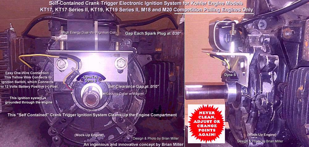
Designed to convert a 12 volt points and condenser ignition system into the more reliable and dependable 100% digital 12 volt electronic ignition system. Points and condenser cannot be used with this ignition system. Remove the points and condenser and cover the points pushrod hole with the supplied block-off plate with silicone sealant. Invented by A-1 Miller's. Please do not accept an advertised copycat product of this kind. (Copywrite infringement.)
Crank Trigger Electronic Ignition System with the Self-Contained Dynatek Dyna S Sensor/Module and an Incorporated High Energy Ignition Coil Fastened on an Angled Aluminum Mounting Plate, and Set Screw collar w/Embedded Magnet for Kohler Engine Models KT17 (first design), KT17 Series II, KT19 (first design), KT19 Series II, KT21, M18 and M20 Competition Pulling Engines Only. Requires 12 volts DC negative ground of power. Being the aftermarket and OEM Magnum M18 and M20 solid state electronic armature ignition coils will hold up to around 3,600 RPM, when used at higher RPM, the secondary windings within the coil tend to overheat, causing the coil to eventually fail. But this custom-made ignition system helps the engine to rev to its maximum without failing. It works flawlessly and may outlast the life of the engine. It operates off the PTO end of the engine and is mainly for competition pulling engines that have nothing on the PTO end of the crankshaft. The high energy dual-spark plug wire compact armature ignition coil is fastened above the Dynatek Dyna S module on a sturdy aluminum mounting plate; cleans up the engine compartment. IMPORTANT: When ordering, please indicate the bolt hole spacing (measurement) for mounting the angle bracket to the rear closure plate on the PTO end of the engine. Or customer can machine their own adjustable slotted mounting holes. This high-performance ignition system have been thoroughly tested under extreme conditions, and produces a stable and a very strong spark with the use of microelectronics, even with the compact armature ignition coil, helping the engine to start quicker, idle smoothly and rev up to full RPM with no hesitation whatsoever. The Dynatek Dyna S sensor/module is triggered by a small magnet embedded in an aluminum set screw collar (magnet ring) that's fastened on the crankshaft. Use this setup for durability when the solid state armature ignition coil keeps failing for no apparent reason. All replacement ignition parts are readily available. Simple one wire hook-up; RED wire on sensor/module connects to 12 volt ignition switch (which connects to the positive (+) battery post). This ignition system is grounded through the engine. NOTE: For easier setting of the timing with this electronic ignition module, use a permanent ink marker (Sharpie, Magic Marker, Marks-A-Lot, etc.) on the side of the collar in alignment with the magnet to indicate the location of the magnet. Kit includes: Dynatek Dyna S sensor/module and high energy dual wire epoxy-encapsulated armature ignition coil with two molded-in metal core coil-to-spark plug wires and 90º spark plug terminals/boots fastened on aluminum mounting plate, and small magnet embedded in an aluminum set screw collar (magnet ring), and new battery ignition OFF-IGNITION-START key switch (do not reuse OEM Magnum solid state ignition key switch with this system) or momentary push button starter switch (to crank the engine), OFF-ON toggle switch or an OFF-ON key switch (for security purposes; to power the ignition) and fully insulated male and female slip-on spade crimp-type wire connectors (to easily connect/disconnect the ignition system to/from the power source). Remove the OEM solid state armature ignition coil and aluminum bracket. They will serve no purpose with this kit. Use with metal core spark plugs gapped at .030" each. When the ignition unit is installed and wire(s) correctly connected, turn the ignition switch on to supply power to the coil, and rotate the flywheel back and forth by hand so the magnet passes the module and observe for a strong, audible "snappy" blue spark at the spark plug's tip(s). FYI - The blue color is made by burning of nitrogen and oxygen in the atmosphere when they are energized, and the snapping sound is breaking of the sound barrier, resulting in a very tiny sonic boom released from the rapid burning and explosion of the nitrogen and oxygen. Please specify diameter of crankshaft PTO end for set screw collar w/embedded magnet. IMPORTANT: Use a new copper core/non-resistor AC Delco, Autolite or Champion spark plug of the correct type gapped at .025" for longer coil life. Use of resistor type spark plugs will void warranty. Coil can withstand high engine vibration. Please specify diameter of crankshaft PTO end for the set screw collar when ordering. Click here to learn how to set the ignition timing on a KT17 (first design), KT17 Series II, KT19 (first design) KT19 Series II, KT21, M18 or M20 engine with crank trigger ignition.
Aluminum Set Screw collar
w/Embedded Trigger Magnet (Magnet Ring). Use with Dynatek Dyna S, hall
effect electronic ignition module, hall effect proximity sensors (listed
below) and/or digital tachometer
(with hall effect proximity sensor). When ordering, please specify diameter
of crankshaft PTO end or shaft it's to be mounted on. Various OEM Kohler
crankshaft PTO end diameters are 3/4", 1", 1-1/8", 1-1/4", 1-3/8", 1-7/16"
and 1-1/2". Most billet steel crankshafts have a 1-1/2" diameter raised shoulder
on the PTO end. Other sizes available. NOTE: For easier setting of the
timing with the electronic ignition module, use a permanent ink marker
(Sharpie,
Magic Marker,
Marks-A-Lot, etc.) on the side of the set screw collar
in alignment with the magnet to indicate the location of the magnet. Other
sizes available. $30.00 each, plus shipping & handling. Please
let me know if you're interested in purchasing this
part and I'll give you the total amount with shipping and payment options.
[Return to previous section]
Points Pushrod Hole Block-Off
Plate. Fits Kohler engine models K90/K91, K141, K160/K161,
KV161,
L160/L161, L181,
K181, K241, K301, K321, K341, K361, KT17 (first design), KT17 Series II,
KT19 (first design) KT19 Series II, KT21, K482, K532 and K582. Use this part
to cover points pushrod hole when converting engine to electronic ignition.
(Listed in this website.) Apply RTV silicone sealant to prevent oil leak
and use the OEM ignition points mounting screws to secure plate in place.
A-1 Miller's fabricated part. $10.00 each, plus shipping & handling.
Click here to contact A-1 Miller's for FREE honest and accurate technical support and/or for ordering information and payment options. Please contact A-1 Miller's if you need part(s) and/or service(s) performed that's not listed or mentioned in this website. [Top of Page]
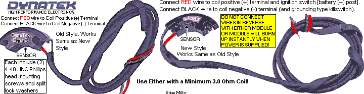 Replacement Dynatek Dyna S
Sensor/Modules. IMPORTANT: Use with minimum 3.0 ohm coil to prevent burning
up module! Click
here to learn how to check the primary ohms resistance in a coil. Simple
wiring instructions: Connect the RED
wire to the coil positive [+] terminal (which connects to the ignition switch
and battery positive (+) post), and connect the BLACK wire to the
coil negative (–) terminal, and self-grounding kill switch (pulling
tractor). There are no other wire(s) that connects to the negative (–)
terminal on the coil. The mounting base of the sensor/module is grounded
to the engine and negative (–) battery post.
IMPORTANT
- Use dielectric grease between the module/sensor and aluminum mounting plate
to dissipate the normal operating heat with cool circulating air. And the
module will burn up after a few minutes up if the ignition switch is left
on with the engine not running. To prevent this from possibly happening and/or
for security reasons, use an OFF-ON key switch and/or a
master disconnect switch with a removable
key instead of just a toggle switch to power the ignition system.
To test if the module is good or bad, with an analog or digital
multimeter set on the Ohms resistance, connect one lead to the BLACK
wire and the other lead to the mounting base. If the meter shows no resistance,
the module is good. But if it shows resistance, the module is bad (shorted
out internally). Use with aluminum set screw collar w/embedded magnet (magnet
ring; listed below) on PTO end of crankshaft to trigger the spark.
Replacement Dynatek Dyna S
Sensor/Modules. IMPORTANT: Use with minimum 3.0 ohm coil to prevent burning
up module! Click
here to learn how to check the primary ohms resistance in a coil. Simple
wiring instructions: Connect the RED
wire to the coil positive [+] terminal (which connects to the ignition switch
and battery positive (+) post), and connect the BLACK wire to the
coil negative (–) terminal, and self-grounding kill switch (pulling
tractor). There are no other wire(s) that connects to the negative (–)
terminal on the coil. The mounting base of the sensor/module is grounded
to the engine and negative (–) battery post.
IMPORTANT
- Use dielectric grease between the module/sensor and aluminum mounting plate
to dissipate the normal operating heat with cool circulating air. And the
module will burn up after a few minutes up if the ignition switch is left
on with the engine not running. To prevent this from possibly happening and/or
for security reasons, use an OFF-ON key switch and/or a
master disconnect switch with a removable
key instead of just a toggle switch to power the ignition system.
To test if the module is good or bad, with an analog or digital
multimeter set on the Ohms resistance, connect one lead to the BLACK
wire and the other lead to the mounting base. If the meter shows no resistance,
the module is good. But if it shows resistance, the module is bad (shorted
out internally). Use with aluminum set screw collar w/embedded magnet (magnet
ring; listed below) on PTO end of crankshaft to trigger the spark.
Click here to contact A-1 Miller's for FREE honest and accurate technical support and/or for ordering information and payment options. Please contact A-1 Miller's if you need part(s) and/or service(s) performed that's not listed or mentioned in this website. [Top of Page] [Return to previous paragraph, section or website]
How to Test for Spark and Set the Timing for the electronic ignition
sensor/modules - After either setup is installed on the engine and power
is supplied, simply rotate the set screw collar w/embedded magnet (loose)
on the crankshaft back and forth by hand. Each time the embedded detector/trigger
magnet passes the sensor/module, spark should occur.
 NOTE: Do not use a
battery charger in place of the battery to perform this
test. Battery chargers constantly switch between high and low voltage at
60 cycles per second, and the module sees this as the ignition constantly
being switched on and off, resulting in a continuous array of sparks.
NOTE: Do not use a
battery charger in place of the battery to perform this
test. Battery chargers constantly switch between high and low voltage at
60 cycles per second, and the module sees this as the ignition constantly
being switched on and off, resulting in a continuous array of sparks.
A simple and precise way to set the ignition timing STATICALLY (engine not running) for either sensor/module -
How to accurately set the ignition timing STATICALLY for the Electronic Ignition Module or Inductive 3-Wire Proximity sensor/module - (This is also how to test if the sensor/modules or the ignition system is functioning or not.)
How to precisely set the ignition timing DYNAMICALLY (engine running) using a strobe timing light for either sensor/module. (This is the most accurate way to set the timing.) NOTE: Timing can be checked, but not set while the engine is running! Do not allow sensor/module to make contact with the set screw collar w/embedded magnet while engine is running! -
How to Safely Bench Test the DynaTek Dyna S or PerTronix Ignitor hall effect modules. This process checks if the internal switching transistor is successfully triggering when the magnet passes it. Exception: the head of a small steel screw or steel nail instead of a magnet will be required for the inductive type PerTronix Ignitor.
Equipment Needed:
NOTE: Do not use a
battery charger in place of the battery to perform this
test. Battery chargers constantly switch between high and low voltage at
60 cycles per second, and the module sees this as the ignition constantly
being switched on and off, resulting in a continuous array of sparks.
Step-by-Step Test Procedure:
Reliable and Durable Tachometers and Hour Meter [Return to Previous Section, Paragraph or Website]
 High Quality Small Engine
Inductive Tachometer/Hour Meter with Replaceable Battery. A tachometer
is required for monitoring and/or setting the maximum speed of a small engine,
which is normally 3,200 or 3,600 RPM (depending on type of carburetor), to
prevent from over-revving and possible damage to the engine or dangerous
flywheel explosion. Very accurate, vibration-proof and weatherproof construction.
Can be surface-mounted and secured with two screws to monitor engine RPM,
or hand-held to set engine RPM. Large 3/8 inch LCD display. Works with magneto
or battery-powered ignition systems by selecting engine type by programming
S1 and S2 buttons. If tachometer does not turn on automatically as soon
as engine starts, press and hold the two buttons at the same time.
Instructions included. Reads up to 99,999 RPM. Hour meter reads up to 9999:59
hours/minutes. Programmable maintenance hour setting with service icon, a
service reminder when to change oil or other maintenance. Can be manually
reset to Zero hours. Easy installation: Single wire wraps around spark plug
wire and secured with two supplied nylon zip-ties. No wire terminal connections
required. Includes replaceable CR2450 battery. Dimensions: 2" wide x 1-3/4"
depth x 3/4" height. $25.00 each, plus shipping & handling.
Click here to print out
instructions. Please let me know if you're
interested in purchasing this item and I'll give you the total amount with
shipping and payment options.
High Quality Small Engine
Inductive Tachometer/Hour Meter with Replaceable Battery. A tachometer
is required for monitoring and/or setting the maximum speed of a small engine,
which is normally 3,200 or 3,600 RPM (depending on type of carburetor), to
prevent from over-revving and possible damage to the engine or dangerous
flywheel explosion. Very accurate, vibration-proof and weatherproof construction.
Can be surface-mounted and secured with two screws to monitor engine RPM,
or hand-held to set engine RPM. Large 3/8 inch LCD display. Works with magneto
or battery-powered ignition systems by selecting engine type by programming
S1 and S2 buttons. If tachometer does not turn on automatically as soon
as engine starts, press and hold the two buttons at the same time.
Instructions included. Reads up to 99,999 RPM. Hour meter reads up to 9999:59
hours/minutes. Programmable maintenance hour setting with service icon, a
service reminder when to change oil or other maintenance. Can be manually
reset to Zero hours. Easy installation: Single wire wraps around spark plug
wire and secured with two supplied nylon zip-ties. No wire terminal connections
required. Includes replaceable CR2450 battery. Dimensions: 2" wide x 1-3/4"
depth x 3/4" height. $25.00 each, plus shipping & handling.
Click here to print out
instructions. Please let me know if you're
interested in purchasing this item and I'll give you the total amount with
shipping and payment options.
 High Quality, Reliable and Durable Digital Tachometer/Proximity
Sensor Kits. A tachometer is required in setting the correct engine RPM,
which is normally 3,200 or 3,600 RPM (depending on type of carburetor), to
prevent from over-revving and possible damage to the engine or dangerous
flywheel explosion. Choice of a RED or
BLUE numeric display. Will work with
most small engines or multi-cylinder automotive engines, gas or diesel. Very
accurate, vibration-proof and weatherproof construction. The great thing
about this type of tachometer is that it needs no setup or programming. Displays
accurate RPM as soon as the engine cranks over to start. Displays up to 9,999
RPM. Tachometer returns to zero [0000] when engine is shut down. Can be used
for lawn & garden equipment or competition pulling engines. Designed
to be permanently mounted to monitor engine RPM at all times. Tachometer
can be in-dash or panel-mounted. This precision digital tachometer operates
with external power and on the same principle as my
flywheel- or
crank-trigger ignition systems with a proximity sensor to detect the
target, which can be a small ferrous steel screw or pin, or magnet in a rotating
disc on the crankshaft or on/in flywheel. Operates totally independent of
the ignition system, or can be used with crank trigger ignition with the
same proximity sensor. Sensor is capable of powering this digital tachometer
and crank-trigger ignition module at the same time, with the exception of
using the electronic ignition modules. This tachometer must be wired separately
or wiring can be incorporated with my crank-trigger ignition system that
use a proximity sensor. A sturdy metal bracket will need to be fabricated
by customer to mount the sensor in close proximity of the detector/trigger
target. Set air gap/clearance at .010"-.188". Tachometer works with 8-24
volts DC, proximity sensor works with 6-36 volts DC. Dimensions for mounting
hole for tachometer: 3" wide x 1-17/32" wide. Tachometer measures 1" in depth.
Dimensions of proximity sensor: 15/32" diameter threads x 1-3/8" thread length.
Click or tap here for YouTube videos to see how well this
tachometer works.
High Quality, Reliable and Durable Digital Tachometer/Proximity
Sensor Kits. A tachometer is required in setting the correct engine RPM,
which is normally 3,200 or 3,600 RPM (depending on type of carburetor), to
prevent from over-revving and possible damage to the engine or dangerous
flywheel explosion. Choice of a RED or
BLUE numeric display. Will work with
most small engines or multi-cylinder automotive engines, gas or diesel. Very
accurate, vibration-proof and weatherproof construction. The great thing
about this type of tachometer is that it needs no setup or programming. Displays
accurate RPM as soon as the engine cranks over to start. Displays up to 9,999
RPM. Tachometer returns to zero [0000] when engine is shut down. Can be used
for lawn & garden equipment or competition pulling engines. Designed
to be permanently mounted to monitor engine RPM at all times. Tachometer
can be in-dash or panel-mounted. This precision digital tachometer operates
with external power and on the same principle as my
flywheel- or
crank-trigger ignition systems with a proximity sensor to detect the
target, which can be a small ferrous steel screw or pin, or magnet in a rotating
disc on the crankshaft or on/in flywheel. Operates totally independent of
the ignition system, or can be used with crank trigger ignition with the
same proximity sensor. Sensor is capable of powering this digital tachometer
and crank-trigger ignition module at the same time, with the exception of
using the electronic ignition modules. This tachometer must be wired separately
or wiring can be incorporated with my crank-trigger ignition system that
use a proximity sensor. A sturdy metal bracket will need to be fabricated
by customer to mount the sensor in close proximity of the detector/trigger
target. Set air gap/clearance at .010"-.188". Tachometer works with 8-24
volts DC, proximity sensor works with 6-36 volts DC. Dimensions for mounting
hole for tachometer: 3" wide x 1-17/32" wide. Tachometer measures 1" in depth.
Dimensions of proximity sensor: 15/32" diameter threads x 1-3/8" thread length.
Click or tap here for YouTube videos to see how well this
tachometer works.
Wiring Instructions:
Wiring is the same for the hall effect and inductive proximity sensors. Certain proximity sensors have an LED (Light Emitting Diode), which flashes when in close proximity of target. If the proximity sensor is wired incorrectly, the LED will illuminate at all times.
Aluminum Set Screw Locking Collar
w/Embedded Magnet. Use with hall effect proximity sensors only. $30.00
each, plus shipping & handling.

 To place an order, send your item(s) for repairing, and/or
for customer service assistance, and FREE honest and accurate technical support,
please contact: A-1 Miller's Performance Enterprises, 12091 N Route B,
Hallsville, MO (Missouri) 65255-9604 USA. Please call in your order or send
an email with a list parts you need and your contact information.
To place an order, send your item(s) for repairing, and/or
for customer service assistance, and FREE honest and accurate technical support,
please contact: A-1 Miller's Performance Enterprises, 12091 N Route B,
Hallsville, MO (Missouri) 65255-9604 USA. Please call in your order or send
an email with a list parts you need and your contact information.
 Phone: 1-573-881-7229 (cell;
call, text or leave voicemail). Please call Monday-Friday, 9am to 5pm, Central
time zone, except holidays. If no answer, please try again later.
Phone: 1-573-881-7229 (cell;
call, text or leave voicemail). Please call Monday-Friday, 9am to 5pm, Central
time zone, except holidays. If no answer, please try again later.
 E-mail:
pullingtractor@aol.com. A-1 Miller's
shop is open to the public Monday-Friday, 9am to 5pm, Central time zone,
with an appointment on weekends, except holidays. If you're the kind of person
who don't trust delivery/shipping companies (mis)handling your high-dollar
and fragile merchandise, you can make the long drive to A-1 Miller's new
shop (click image to the right) to personally purchase parts, or drop off
and/or pick up your carburetor, clutch assembly, and/or other parts for repairing
and/or rebuilding. Or visit our new shop to drop off your parts. Please contact
us before coming so we'll be at our shop waiting for your arrival. When you
visit our shop, you will be dealing directly with the owner for the best
customer service. "The road to a [trusted] friend's house (or shop) is
never long." Don't sacrifice quality workmanship for distance.
Payment Options below.
Photos
of our new building/shop are posted here!
12091 N Route B, Hallsville, MO - Google Maps.
[Return To Previous Paragraph, Section
or Website]
E-mail:
pullingtractor@aol.com. A-1 Miller's
shop is open to the public Monday-Friday, 9am to 5pm, Central time zone,
with an appointment on weekends, except holidays. If you're the kind of person
who don't trust delivery/shipping companies (mis)handling your high-dollar
and fragile merchandise, you can make the long drive to A-1 Miller's new
shop (click image to the right) to personally purchase parts, or drop off
and/or pick up your carburetor, clutch assembly, and/or other parts for repairing
and/or rebuilding. Or visit our new shop to drop off your parts. Please contact
us before coming so we'll be at our shop waiting for your arrival. When you
visit our shop, you will be dealing directly with the owner for the best
customer service. "The road to a [trusted] friend's house (or shop) is
never long." Don't sacrifice quality workmanship for distance.
Payment Options below.
Photos
of our new building/shop are posted here!
12091 N Route B, Hallsville, MO - Google Maps.
[Return To Previous Paragraph, Section
or Website]
Payment Options, and We Ship to Canada and
Worldwide 
Item(s) in a package or cushioned envelope weighing less than 1 lb. is sent
by US Postal Service Airmail Letter Post for a 4-7 days delivery. Packaged
item(s) weighing over 1 lb. and up to 66 lb. is sent by US Postal Service
Airmail Parcel Post for a 4-10 days delivery. I cannot use the US Postal
Services' Flat Rate Priority Mail envelopes and boxes to ship outside U.S.
territories. Item(s) weighing over 67 lbs. or more is sent by FedEx Ground
or equivalent services. We try to keep our shipping cost to customers within
reason. Therefore, we don't ship our products in a fancy-looking package
with our company name and/or logo on it because most customers will just
toss it in the trash after they remove the contents. And being there is no
USPS tracking number outside the US, all I can do is make sure I write your
address correctly on the customs form and on your package.
My websites are not set up to process orders and accept payments. Therefore, I will need your name, complete and correct postal mailing address and phone number. And for payment options, I accept cash (in person), USPS Postal Money Orders, cashier's checks and business checks. I do not accept credit/debit cards. Or to make a payment to me through PayPal, please click this link: https://www.paypal.com (username: pullingtractor@aol.com). And please use PayPal's "Friends and Family" option to ensure that I receive the full amount or add 3% to the total amount to cover PayPal's processing surcharge. I also accept Venmo (username: Pullingtractor) and Cash App (username: pullingtractor) please add 2% for Cash App's surcharge as well). And be sure to mention a description of what the payment is for with your full name, postal address, phone number and email address. If sending a money order or cashier's check, please include a note in the envelope with your name, complete mailing address, phone number, email address and a description of what the payment is for. I'll make a note of your order when I have all your information, and I may have to order some of the parts on your list, which should take a few days to come in, but I will send everything to you as soon as the parts are in stock after I receive your payment.


Return To Previous Website | Top of Page | Copyright © 1996-Present. This website created, designed and maintained by A-1 Miller's Performance Enterprises
 Stainless Steel Points Pushrod.
A-1 Miller's high quality aftermarket part. Replaces discontinued Kohler
aluminum part # 41 411 01-S. $25.00 each, plus shipping & handling.
Stainless Steel Points Pushrod.
A-1 Miller's high quality aftermarket part. Replaces discontinued Kohler
aluminum part # 41 411 01-S. $25.00 each, plus shipping & handling.
 Flared-End Stainless Steel
Points Pushrod. Use this part if the points lobe is severely worn and the
ignition timing cannot be fully advanced to the factory setting of 20º
BTDC. The flared end makes contact with unworn sides or areas of points lobe
so ignition timing can be fully advanced to 20º BTDC. NOTE: Entire
engine must be completely disassembled, and install this part from inside
crankcase or governor assembly. A-1 Miller's high quality aftermarket
part. $20.00 each, plus shipping & handling.
Flared-End Stainless Steel
Points Pushrod. Use this part if the points lobe is severely worn and the
ignition timing cannot be fully advanced to the factory setting of 20º
BTDC. The flared end makes contact with unworn sides or areas of points lobe
so ignition timing can be fully advanced to 20º BTDC. NOTE: Entire
engine must be completely disassembled, and install this part from inside
crankcase or governor assembly. A-1 Miller's high quality aftermarket
part. $20.00 each, plus shipping & handling.
 Stainless Steel Points Pushrod.
OEM Kohler part # 47 411 04-S (was 46 411 01-S). $22.10 each, plus
shipping & handling.
Stainless Steel Points Pushrod.
OEM Kohler part # 47 411 04-S (was 46 411 01-S). $22.10 each, plus
shipping & handling.
 Thin-Wall Brass Sleeve Bushing
for Points Pushrod. Use this to repair worn 3/16" points pushrod hole in
governor assembly for Kohler engine models K482, K532 and K582. To install,
the points pushrod hole will need to be precision-aligned bored (enlarged)
exactly to .218" with a chucking reamer for a press-fit installation. Dimensions:
3/16" I.D. x 7/32" O.D. x 5/8" length. $4.00 each, plus shipping &
handling.
Thin-Wall Brass Sleeve Bushing
for Points Pushrod. Use this to repair worn 3/16" points pushrod hole in
governor assembly for Kohler engine models K482, K532 and K582. To install,
the points pushrod hole will need to be precision-aligned bored (enlarged)
exactly to .218" with a chucking reamer for a press-fit installation. Dimensions:
3/16" I.D. x 7/32" O.D. x 5/8" length. $4.00 each, plus shipping &
handling.
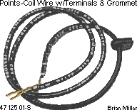 "Ready to Install"
Points-to-Ignition Coil Wire Kits. Replace OEM wire with frayed/cracked
insulation and/or broken connector(s) to prevent a short circuit and/or engine
misfire. Or use this when converting from Breakerless Ignition to points
and condenser ignition. Fits Kohler engines with battery-powered ignition,
models K90/K91, K141, K160/K161,
"Ready to Install"
Points-to-Ignition Coil Wire Kits. Replace OEM wire with frayed/cracked
insulation and/or broken connector(s) to prevent a short circuit and/or engine
misfire. Or use this when converting from Breakerless Ignition to points
and condenser ignition. Fits Kohler engines with battery-powered ignition,
models K90/K91, K141, K160/K161,
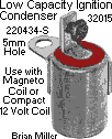 Low Capacity Ignition
Condenser/
Low Capacity Ignition
Condenser/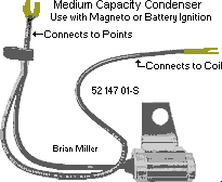
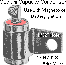 Medium Capacity Ignition
Condensers/
Medium Capacity Ignition
Condensers/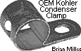 OEM Kohler condenser clamp w/9/32"
mounting hole. Allows high-output/performance condenser (listed above) be
mounted next to coil with one of coil's mounting bracket bolts. Or could
be used as a wire clamp for bundle of wires. Used and in excellent condition.
Irrelevant Kohler part number. $2.00 each, plus shipping & handling.
OEM Kohler condenser clamp w/9/32"
mounting hole. Allows high-output/performance condenser (listed above) be
mounted next to coil with one of coil's mounting bracket bolts. Or could
be used as a wire clamp for bundle of wires. Used and in excellent condition.
Irrelevant Kohler part number. $2.00 each, plus shipping & handling.
 High Quality Copper Core/Non-Resistor
Spark Plugs. Designed for most larger cast iron block Briggs & Stratton
engines, Kohler engine models K141, K160/K161,
High Quality Copper Core/Non-Resistor
Spark Plugs. Designed for most larger cast iron block Briggs & Stratton
engines, Kohler engine models K141, K160/K161,
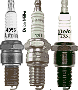 High Quality Copper
Core/Non-Resistor Spark Plugs for use in machined billet cylinder heads
for competition pulling only. Designed for Kohler engine models K241,
M10, K301, M12, K330/K331, K321, M14 , K341 and M16. Along with a metal core
spark wire, copper core spark plugs provide a stronger spark that allow the
ignition coil to operate cooler, last longer and provide the highest possible
energy to ensure maximum ignition potential. For best engine performance
and longevity of the coil, set gap at .025" with a self-energizing magneto
or solid state electronic ignition system, .035" with a full size battery-powered
ignition coil, and .060" with a high-output/performance battery-powered coil.
14mm threads x 3/4" thread reach, flat washer seat. Irrelevant Kohler part
number.
High Quality Copper
Core/Non-Resistor Spark Plugs for use in machined billet cylinder heads
for competition pulling only. Designed for Kohler engine models K241,
M10, K301, M12, K330/K331, K321, M14 , K341 and M16. Along with a metal core
spark wire, copper core spark plugs provide a stronger spark that allow the
ignition coil to operate cooler, last longer and provide the highest possible
energy to ensure maximum ignition potential. For best engine performance
and longevity of the coil, set gap at .025" with a self-energizing magneto
or solid state electronic ignition system, .035" with a full size battery-powered
ignition coil, and .060" with a high-output/performance battery-powered coil.
14mm threads x 3/4" thread reach, flat washer seat. Irrelevant Kohler part
number.
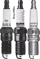 High Quality Copper
Core/Non-Resistor Spark Plugs. Designed for most models of Onan opposed
twin-cylinder air-cooled small engines. Along with a metal core spark wire,
copper core spark plugs provide a stronger spark that allow the ignition
coil to operate cooler, last longer and provide the highest possible energy
to ensure maximum ignition potential. For best engine performance and longevity
of the coil, set gap at .025" with a self-energizing magneto or solid state
electronic ignition system, .035" with a full size battery-powered ignition
coil, and .060" with a high-output/performance battery-powered coil. 14mm
threads x 11/16" thread reach, flat washer seat.
High Quality Copper
Core/Non-Resistor Spark Plugs. Designed for most models of Onan opposed
twin-cylinder air-cooled small engines. Along with a metal core spark wire,
copper core spark plugs provide a stronger spark that allow the ignition
coil to operate cooler, last longer and provide the highest possible energy
to ensure maximum ignition potential. For best engine performance and longevity
of the coil, set gap at .025" with a self-energizing magneto or solid state
electronic ignition system, .035" with a full size battery-powered ignition
coil, and .060" with a high-output/performance battery-powered coil. 14mm
threads x 11/16" thread reach, flat washer seat.

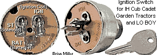
 1/4" Width Slide-On Brass
Spade Crimp Wire Connector with Locking Tab/Tang. Replace damaged brass
connector(s) to insure 100% electrical connections for reliability. Fits
plastic housing electrical connectors used on most OFF-ON-START key switches,
voltage rectifier/regulators, head lights, etc. FYI - Solder or use
1/4" Width Slide-On Brass
Spade Crimp Wire Connector with Locking Tab/Tang. Replace damaged brass
connector(s) to insure 100% electrical connections for reliability. Fits
plastic housing electrical connectors used on most OFF-ON-START key switches,
voltage rectifier/regulators, head lights, etc. FYI - Solder or use

 Universal, High Quality
Epoxy-Encapsulated 12 Volt 4.0 ohm Armature Ignition Coil w/Integrated Dual
21" Length Metal Core Spark Plug Wires for Opposed Twin Cylinder Engines.
Can be used on Kohler engine models KT17, KT17 Series II, KT19, KT19 Series
II, KT21, K482, K532, K582, K660/K662, Onan opposed twin cylinder engines,
or virtually any opposed twin cylinder small engine with a fabricated bracket.
Mounting hardware included for custom applications. Two 90º spark plug
boots and terminals included. Can be used with A-1 Miller's custom-made
Universal, High Quality
Epoxy-Encapsulated 12 Volt 4.0 ohm Armature Ignition Coil w/Integrated Dual
21" Length Metal Core Spark Plug Wires for Opposed Twin Cylinder Engines.
Can be used on Kohler engine models KT17, KT17 Series II, KT19, KT19 Series
II, KT21, K482, K532, K582, K660/K662, Onan opposed twin cylinder engines,
or virtually any opposed twin cylinder small engine with a fabricated bracket.
Mounting hardware included for custom applications. Two 90º spark plug
boots and terminals included. Can be used with A-1 Miller's custom-made
 Epoxy-Encapsulated 12 Volt
4.0 ohm Canister Ignition Coils for Opposed Twin Cylinder Engine. Each
coil below fits Kohler engine models KT17, KT17 Series II, KT19 and KT19
Series II. Can be used with A-1 Miller's custom-made
Epoxy-Encapsulated 12 Volt
4.0 ohm Canister Ignition Coils for Opposed Twin Cylinder Engine. Each
coil below fits Kohler engine models KT17, KT17 Series II, KT19 and KT19
Series II. Can be used with A-1 Miller's custom-made
 Epoxy-Encapsulated 12 Volt
Ignition Coils for Opposed Twin Cylinder Engine. Each listed below fits
Kohler engine models K482, K532, K582, or virtually any opposed twin cylinder
small engine with a fabricated bracket. Can be used with A-1 Miller's custom-made
Epoxy-Encapsulated 12 Volt
Ignition Coils for Opposed Twin Cylinder Engine. Each listed below fits
Kohler engine models K482, K532, K582, or virtually any opposed twin cylinder
small engine with a fabricated bracket. Can be used with A-1 Miller's custom-made
 removed
the new armature/stator assembly and reinstalled the original armature/stator
assembly; installed a new OEM Kohler magneto armature ignition coil on the
armature; and even tried a different flywheel, but with all of these things,
one after the other, the engine would still die out above idle, no matter
what. Then I connected a temporary battery-powered ignition system with jumper
wires with alligator clips just to find if the engine would rev up at open
throttle, and it did, with no problems! Then after all of this, I found that
the charging system would not generate the full 10 amps to recharge the battery.
It would only generate about 3 amps. (The tractor had a factory-installed
amp gauge.) The voltage rectifier/regulator was in good condition too, but
there was nothing I could do to fix this.
removed
the new armature/stator assembly and reinstalled the original armature/stator
assembly; installed a new OEM Kohler magneto armature ignition coil on the
armature; and even tried a different flywheel, but with all of these things,
one after the other, the engine would still die out above idle, no matter
what. Then I connected a temporary battery-powered ignition system with jumper
wires with alligator clips just to find if the engine would rev up at open
throttle, and it did, with no problems! Then after all of this, I found that
the charging system would not generate the full 10 amps to recharge the battery.
It would only generate about 3 amps. (The tractor had a factory-installed
amp gauge.) The voltage rectifier/regulator was in good condition too, but
there was nothing I could do to fix this.
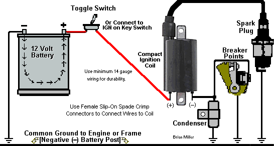
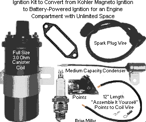
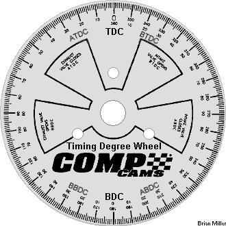
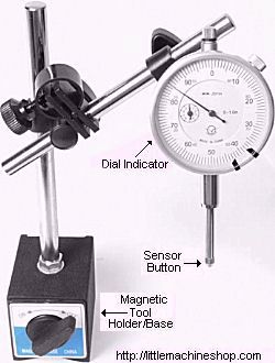
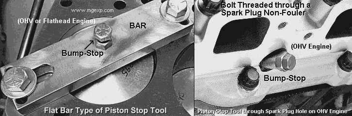 A
A
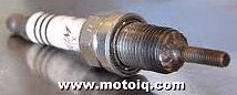 The plug-type piston stop can
be used on a flathead engine, or it can be used on an OHV engine if the spark
plug sits at an angle to the piston. If the spark plug is perpendicular (at
a 90º angle) with the head, a long-reach (long threaded) spark plug
can be used in the head to serve as the bump-stop. Up and down or in and
out adjustment of the the very long spark plug is made to "stop" the piston.
Simply fasten the head on the block with a couple of bolts with the plug
over the piston. The spark plug can be adjusted up or down to find true Top
Dead Center (TDC) of the piston in relationship with the degree wheel. A
blunt-end (not to damage the piston) steel rod may need to be welded on the
end of the plug for an extended reach.
The plug-type piston stop can
be used on a flathead engine, or it can be used on an OHV engine if the spark
plug sits at an angle to the piston. If the spark plug is perpendicular (at
a 90º angle) with the head, a long-reach (long threaded) spark plug
can be used in the head to serve as the bump-stop. Up and down or in and
out adjustment of the the very long spark plug is made to "stop" the piston.
Simply fasten the head on the block with a couple of bolts with the plug
over the piston. The spark plug can be adjusted up or down to find true Top
Dead Center (TDC) of the piston in relationship with the degree wheel. A
blunt-end (not to damage the piston) steel rod may need to be welded on the
end of the plug for an extended reach.
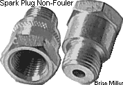 To check and adjust the ignition
(or
To check and adjust the ignition
(or 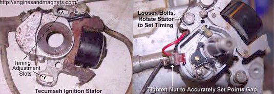 Make sure inside the points
compartment, points contacts, rubbing block (points lobe) and
Make sure inside the points
compartment, points contacts, rubbing block (points lobe) and
 (right-hand or normal rotation
of an
(right-hand or normal rotation
of an
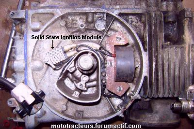 To install a
 New High Quality
Ford/Mercury/Lincoln Electronic Ignition Control Module/Unit for a custom
crank- or flywheel-triggered electronic ignition to use with virtually any
small engine or automotive engine. Requires 12 volts DC negative ground of
power and no ballast resistor. This module can be used with the magnetic
pickup coil or proximity sensor and virtually any ignition coil, regardless
of the ohm resistance or voltage output for a very strong spark, and will
produce a stronger spark to help the engine to start quicker, idle smoothly
and rev up to full RPM with no hesitation whatsoever. Turns the stock coil
into a high-performance coil without shortening the life of the coil. A metal
core spark plug wire and copper core/non-resistor spark plug should be used
with virtually any ignition system to guarantee a strong spark and from burning
up the coil.
New High Quality
Ford/Mercury/Lincoln Electronic Ignition Control Module/Unit for a custom
crank- or flywheel-triggered electronic ignition to use with virtually any
small engine or automotive engine. Requires 12 volts DC negative ground of
power and no ballast resistor. This module can be used with the magnetic
pickup coil or proximity sensor and virtually any ignition coil, regardless
of the ohm resistance or voltage output for a very strong spark, and will
produce a stronger spark to help the engine to start quicker, idle smoothly
and rev up to full RPM with no hesitation whatsoever. Turns the stock coil
into a high-performance coil without shortening the life of the coil. A metal
core spark plug wire and copper core/non-resistor spark plug should be used
with virtually any ignition system to guarantee a strong spark and from burning
up the coil. 

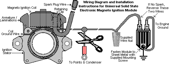 Fasten the module to the engine
sheet metal that has plenty of cool, circulating air with the supplied mounting
screw.
Fasten the module to the engine
sheet metal that has plenty of cool, circulating air with the supplied mounting
screw.

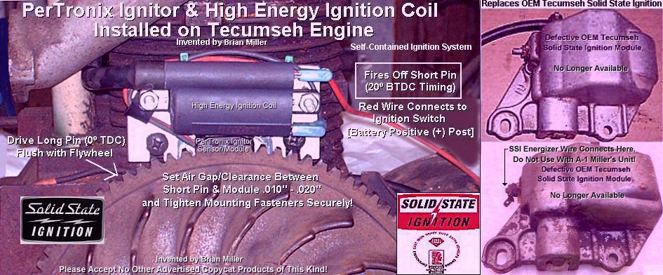
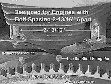


 A-1 Miller's Custom-Made, Reliable and Maintenance-Free
12 Volt Replacement Electronic Ignition Kit for Tecumseh Engine Models VH80,
VH100, HH80, HH100, HH120, OH120, OH140, OH150, OH160 and OH180 with a
gear starter that have a failed OEM Solid State Ignition Module as shown
to the right ->. Fits Tecumseh engine blocks with two bosses with the
2-13/16" bolt hole spacing for the OEM SSI module. This will NOT work on
a Tecumseh engine with a starter/generator because there are no protruding
pins on the edge of the flywheel to trigger the spark. This replacement
ignition system utilizes the PerTronix Ignitor sensor/module and high energy
ignition coil, which installs in place of the OEM Tecumseh Solid State Ignition
(SSI) module unit and is completely hidden under the flywheel shroud,
with no external ignition components exposed, with only one wire connection
to the ignition switch. Works great for lawn & garden, and generator/welder
engines! This ignition system works flawlessly and may outlast the life of
the engine. This high-performance ignition system have been thoroughly tested
under extreme conditions, and produces a stable and a very strong spark with
the use of
A-1 Miller's Custom-Made, Reliable and Maintenance-Free
12 Volt Replacement Electronic Ignition Kit for Tecumseh Engine Models VH80,
VH100, HH80, HH100, HH120, OH120, OH140, OH150, OH160 and OH180 with a
gear starter that have a failed OEM Solid State Ignition Module as shown
to the right ->. Fits Tecumseh engine blocks with two bosses with the
2-13/16" bolt hole spacing for the OEM SSI module. This will NOT work on
a Tecumseh engine with a starter/generator because there are no protruding
pins on the edge of the flywheel to trigger the spark. This replacement
ignition system utilizes the PerTronix Ignitor sensor/module and high energy
ignition coil, which installs in place of the OEM Tecumseh Solid State Ignition
(SSI) module unit and is completely hidden under the flywheel shroud,
with no external ignition components exposed, with only one wire connection
to the ignition switch. Works great for lawn & garden, and generator/welder
engines! This ignition system works flawlessly and may outlast the life of
the engine. This high-performance ignition system have been thoroughly tested
under extreme conditions, and produces a stable and a very strong spark with
the use of
 This ignition system utilizes
the self-contained PerTronix Ignitor or Ignitor II sensor/module electronic
ignition, which works flawlessly, is very reliable and may outlast the life
of the engine. Each Ignitor allows a stock coil perform like a high-performance
one without shortening the life of the coil. This high-performance ignition
system have been thoroughly tested under extreme conditions, and produces
a stable and a very strong spark with the use of
This ignition system utilizes
the self-contained PerTronix Ignitor or Ignitor II sensor/module electronic
ignition, which works flawlessly, is very reliable and may outlast the life
of the engine. Each Ignitor allows a stock coil perform like a high-performance
one without shortening the life of the coil. This high-performance ignition
system have been thoroughly tested under extreme conditions, and produces
a stable and a very strong spark with the use of
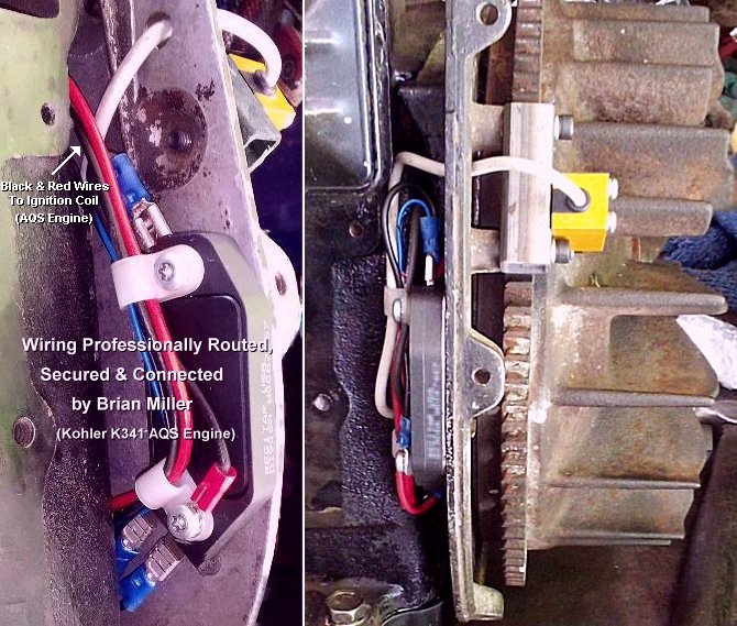
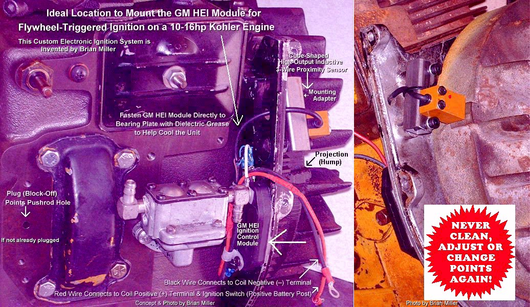
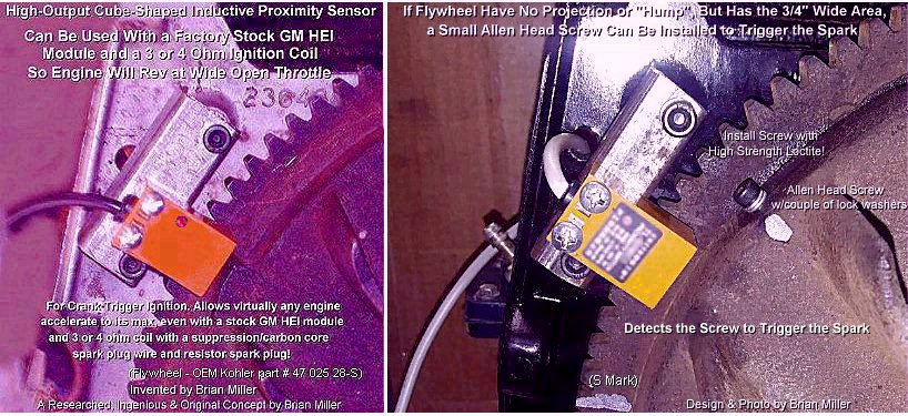
 two 8-32 UNC x 1" hex head
self-threading screws (not self-tapping) and two flat washers (to create
an air space for cooling of module).
two 8-32 UNC x 1" hex head
self-threading screws (not self-tapping) and two flat washers (to create
an air space for cooling of module).
 Mounting of module requires
two 9/64" drilled holes. Module can be remotely mounted on a flat surface
with cool, circulating air, or to install module behind bearing plate, use
a
Mounting of module requires
two 9/64" drilled holes. Module can be remotely mounted on a flat surface
with cool, circulating air, or to install module behind bearing plate, use
a
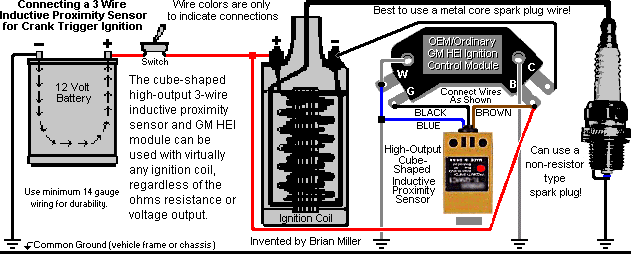 Connect the BLACK
wire on the sensor to the [G] terminal on the module.
Connect the BLACK
wire on the sensor to the [G] terminal on the module.
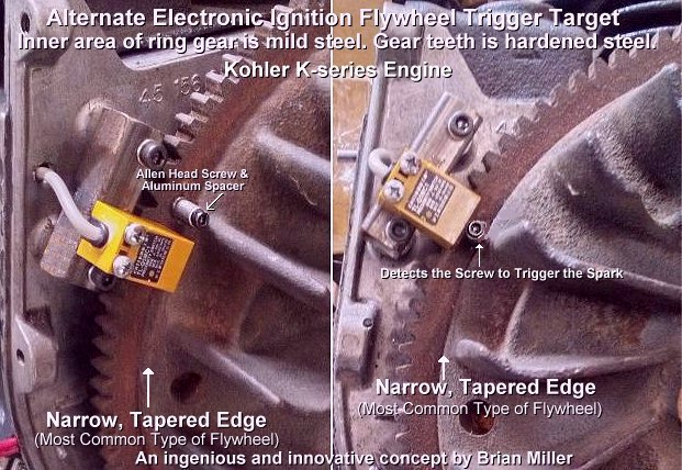 List of Parts in Kit
Includes:
List of Parts in Kit
Includes:

 High Output Cube-Shaped 3-Wire
Inductive Proximity Sensor. Operates with 6-36 volts DC negative ground.
Very versatile. This sensor can be used for many applications; ignition
or electrical. 59" length cable wire. This sensor is capable of powering
the GM 4-pin HEI crank-trigger ignition control module and a digital
High Output Cube-Shaped 3-Wire
Inductive Proximity Sensor. Operates with 6-36 volts DC negative ground.
Very versatile. This sensor can be used for many applications; ignition
or electrical. 59" length cable wire. This sensor is capable of powering
the GM 4-pin HEI crank-trigger ignition control module and a digital