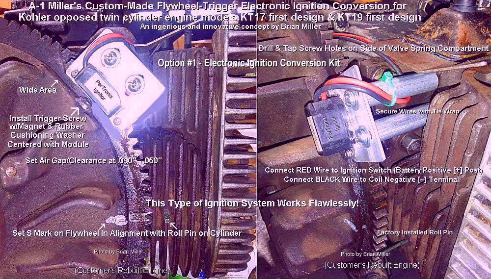
Electronic Ignition Conversion Kit below specifically made for KT17 first design and KT19 first design engines includes: New PerTronix Ignitor hall effect module/sensor fastened on adjustable/slotted aluminum mounting plate, two 10-24 UNC screws w/flat washers and lock washers, two aluminum spacers, target screw w/magnet and rubber cushioning washer, two new Autolite 26 or Champion 25 (RV17YC) spark plugs, and points pushrod hole block-off plate (use with silicone sealant). Use this ignition system with the OEM off-ignition-start key switch and dual wire ignition coil.
INSTALLATION INSTRUCTIONS for KT17 first design and KT19 first design engines. This option can also be used on the KT17 Series II and KT19 Series II engines, and perhaps Magnum engines with the KT-series flywheel installed. Video of this ignition system installed on a running engine coming soon.
 Use a
Sharpie metallic silver permanent marker to locate and
install the
Use a
Sharpie metallic silver permanent marker to locate and
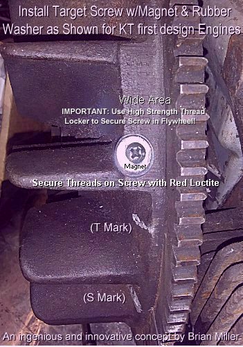
install the  trigger screw w/magnet
and rubber cushioning washer on the flat area on the flywheel above the
T mark as shown in the picture to the right. This will place the ignition
timing in alignment with the center of the PerTronix Ignitor module/sensor
when the S mark on the flywheel is in exact alignment with
the roll pin on the cylinder (which is positioned at 23º BTDC). The
screw head is magnetized to trigger the spark. There is no need to remove
the flywheel to drill and tap the threads. The screw hole must be professionally
drilled and tapped
to accept the supplied 6-32 UNC trigger screw with a [preferably]
TAPER hand tap.
Click here to learn
how to professionally cut new threads. To prevent from breaking off
drill bit or tap, secure the flywheel so it does not rotate one way or the
other while drilling hole and/or cutting threads! NOTE: The rubber
washer prevents the brittle rare earth/neodymium magnet from breaking when
the screw is tightened. IMPORTANT: Secure the screw in the flywheel with
high strength liquid threadlocker
(Red Loctite, Permatex or equivalent) and tighten
it just until the rubber washer begin to bulge. The PerTronix Ignitor hall
effect module/sensor is activated by the South pole of the magnet, so do
not remove the magnet from the screw. FYI - Store a container of liquid
threadlocker or Super Glue upright and not laying flat. The capped tip will
not dry out and clog when stored upright.
trigger screw w/magnet
and rubber cushioning washer on the flat area on the flywheel above the
T mark as shown in the picture to the right. This will place the ignition
timing in alignment with the center of the PerTronix Ignitor module/sensor
when the S mark on the flywheel is in exact alignment with
the roll pin on the cylinder (which is positioned at 23º BTDC). The
screw head is magnetized to trigger the spark. There is no need to remove
the flywheel to drill and tap the threads. The screw hole must be professionally
drilled and tapped
to accept the supplied 6-32 UNC trigger screw with a [preferably]
TAPER hand tap.
Click here to learn
how to professionally cut new threads. To prevent from breaking off
drill bit or tap, secure the flywheel so it does not rotate one way or the
other while drilling hole and/or cutting threads! NOTE: The rubber
washer prevents the brittle rare earth/neodymium magnet from breaking when
the screw is tightened. IMPORTANT: Secure the screw in the flywheel with
high strength liquid threadlocker
(Red Loctite, Permatex or equivalent) and tighten
it just until the rubber washer begin to bulge. The PerTronix Ignitor hall
effect module/sensor is activated by the South pole of the magnet, so do
not remove the magnet from the screw. FYI - Store a container of liquid
threadlocker or Super Glue upright and not laying flat. The capped tip will
not dry out and clog when stored upright.
 Being there are no two bosses
on the #1 cylinder (right side of engine when facing the flywheel) of the
KT17 first design and KT19 first design engines, use the side of the valve
spring compartment casting on the #1 cylinder facing the flywheel to mount
the two supplied posts/supports for the supplied mounting plate with the
ignition module/sensor. See the
[mock up]picture to the right.->
Being there are no two bosses
on the #1 cylinder (right side of engine when facing the flywheel) of the
KT17 first design and KT19 first design engines, use the side of the valve
spring compartment casting on the #1 cylinder facing the flywheel to mount
the two supplied posts/supports for the supplied mounting plate with the
ignition module/sensor. See the
[mock up]picture to the right.->
For customer service assistance, and FREE honest and accurate technical support, please contact: A-1 Miller's Performance Enterprises | 12091 N. Route B | Hallsville, MO (Missouri) 65255 USA | Phone: 1-573-881-7229 (cell/text). Call any day, Monday-Friday, 9am to 5pm, Central time zone. If no answer, please try again later. E-mail: pullingtractor@aol.com.