A-1 Miller's Performance Enterprises | 1501 W. Old Plank Rd. | Columbia,
MO (Missouri) 65203-9136 USA | Phone: 1-573-256-0313 (shop) | 1-573-881-7229
(cell). Please call Monday-Friday (except Holidays), 9am to 5pm, Central
time zone. If no answer, please try again later. (When speaking with Brian,
please be patient because I stutter.) A-1 Miller's shop is open to the
public from 9am to 5pm, including weekends (except Holidays). Please call
before coming so I'll be here waiting for your arrival. Fax:
1-573-449-7347. E-mail:
pullingtractor@aol.com.
Directions to our shop |
1501 West Old Plank Road, Columbia, MO - Google Maps or
Map of 1501 West Old Plank
Road, Columbia, MO by MapQuest.
Converting a Kohler Engine with the starter/Generator to Maintenance-Free
Flywheel-Triggered Electronic Ignition -
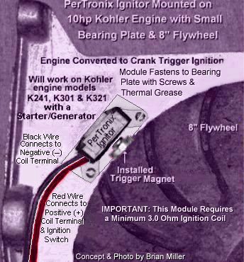
 Flywheel-Trigger Ignition Kit for Kohler engine models K141,
K160/K161, K181, K241, K301 and K321 with the small (8") diameter flywheel
and starter/generator. The PerTronix Ignitor module/sensor sends more
voltage to the coil, which delivers twice the voltage to the spark plug,
increasing horsepower and spark plug life. Hall Effect integrated circuit
means no points to burn, and no moving parts to wear out. Epoxy molding makes
the module impervious to dirt, oil, grease and moisture. Stable timing -
no need for any adjustments. This simple and reliable ignition system system
produces a very strong spark, and the ignition timing will always be set
at 20º BTDC, or wherever you set it. This system can be used on lawn
& garden engines or stock (4,000 RPM) competition pulling engines. Kit
includes a PerTronix Ignitor non-magnetic sensor/module, thermal grease and
mounting screws, small ring magnet/rubber cushioning/isolator washer/mounting
screw (weighs 1/10 oz. / 6 grams). The
sensor is activated by the South pole of the magnet, so do not remove the
magnet from the screw! NOTE: Neodymium and magnets are the strongest
available. Five times stronger than ceramic (ferrite) magnets for stronger
detection. So be extra careful when handling rare earth/neodymium magnets.
They are very brittle and can break when snapped onto something or when the
screw is overtightened. When installing the magnet/screw/rubber washer
on the flywheel, tighten the screw just until the rubber washer begins to
bulge. Secure the screw with
high strength liquid threadlocker
(Red Loctite, Permatex or equivalent). The PerTronix
Ignitor must be used with a minimum 3.0 ohm coil or it may burn up. Most
small engine battery ignition coils have a 3.0 ohm internal primary resistor.
But test your coil just to make sure!
Click or tap here
to learn how to test the ohms resistance in a coil. $75.00 per
kit, plus shipping & handling.
Flywheel-Trigger Ignition Kit for Kohler engine models K141,
K160/K161, K181, K241, K301 and K321 with the small (8") diameter flywheel
and starter/generator. The PerTronix Ignitor module/sensor sends more
voltage to the coil, which delivers twice the voltage to the spark plug,
increasing horsepower and spark plug life. Hall Effect integrated circuit
means no points to burn, and no moving parts to wear out. Epoxy molding makes
the module impervious to dirt, oil, grease and moisture. Stable timing -
no need for any adjustments. This simple and reliable ignition system system
produces a very strong spark, and the ignition timing will always be set
at 20º BTDC, or wherever you set it. This system can be used on lawn
& garden engines or stock (4,000 RPM) competition pulling engines. Kit
includes a PerTronix Ignitor non-magnetic sensor/module, thermal grease and
mounting screws, small ring magnet/rubber cushioning/isolator washer/mounting
screw (weighs 1/10 oz. / 6 grams). The
sensor is activated by the South pole of the magnet, so do not remove the
magnet from the screw! NOTE: Neodymium and magnets are the strongest
available. Five times stronger than ceramic (ferrite) magnets for stronger
detection. So be extra careful when handling rare earth/neodymium magnets.
They are very brittle and can break when snapped onto something or when the
screw is overtightened. When installing the magnet/screw/rubber washer
on the flywheel, tighten the screw just until the rubber washer begins to
bulge. Secure the screw with
high strength liquid threadlocker
(Red Loctite, Permatex or equivalent). The PerTronix
Ignitor must be used with a minimum 3.0 ohm coil or it may burn up. Most
small engine battery ignition coils have a 3.0 ohm internal primary resistor.
But test your coil just to make sure!
Click or tap here
to learn how to test the ohms resistance in a coil. $75.00 per
kit, plus shipping & handling.
Directions to Install This Kit -
-
Remove the points and condenser and block-off the points pushrod hole with
the supplied plug. Failure to do this will cause a major oil leak out
the hole.
-
Align the S mark on the flywheel with the center of the timing sight
hole on the back of the bearing plate or on the side of the flywheel shroud,
and with the flywheel in place and standing still, draw a horizontal line
on the outside of the flywheel and on the bearing plate at the 10:30 position.
This will be the location on the bearing plate to install the PerTronix
Ignitor.
-
On the outside of the flywheel, draw another line vertically or crossway 1"
up or away from the bearing plate with the line that was drawn on the flywheel
to create a + intersection. It is at or near
this location where the trigger screw/magnet/rubber washer is installed in
the flywheel. The screw must be centered with the PerTronix Ignitor to avoid
a misfire.
-
 Very carefully drill and tap
6-32 UNC threads in the flywheel where the two lines intersect and install
the supplied trigger screw/magnet/rubber washer (weighs approximately 1/10
oz. / 2.8 grams) in this spot. The screw head is magnetized to trigger the
spark. This spot allows the screw/magnet/rubber washer to clear the flywheel
shroud mounting boss located at the 4:30 position on the bearing plate.
Click/tap here to
learn how to professionally cut new threads. NOTE: The rubber washer
prevents the high strength but delicate and brittle magnet from possibly
breaking when the screw is tightened to the uneven or rough casting on the
flywheel. IMPORTANT: To prevent from possibly loosening, secure screw in
flywheel or rotating disc with
high strength liquid threadlocker
(Red Loctite, Permatex or equivalent). Tighten
screw just when the rubber begin to bulge, and allow the Loctite to dry and
harden overnight. The PerTronix Ignitor hall effect module/sensor is activated
by the South pole of the magnet, so do not remove the magnet from the
screw!
Very carefully drill and tap
6-32 UNC threads in the flywheel where the two lines intersect and install
the supplied trigger screw/magnet/rubber washer (weighs approximately 1/10
oz. / 2.8 grams) in this spot. The screw head is magnetized to trigger the
spark. This spot allows the screw/magnet/rubber washer to clear the flywheel
shroud mounting boss located at the 4:30 position on the bearing plate.
Click/tap here to
learn how to professionally cut new threads. NOTE: The rubber washer
prevents the high strength but delicate and brittle magnet from possibly
breaking when the screw is tightened to the uneven or rough casting on the
flywheel. IMPORTANT: To prevent from possibly loosening, secure screw in
flywheel or rotating disc with
high strength liquid threadlocker
(Red Loctite, Permatex or equivalent). Tighten
screw just when the rubber begin to bulge, and allow the Loctite to dry and
harden overnight. The PerTronix Ignitor hall effect module/sensor is activated
by the South pole of the magnet, so do not remove the magnet from the
screw!
-
With the S mark on the flywheel aligned or centered with the timing
sight hole in the bearing plate, center the Ignitor with the magnet, allow
.010"-.050" clearance, mark on the bearing plate and drill and tap 6-32 UNC
threads in the bearing plate to mount the Ignitor and spacer.
Click/tap here to learn
how to professionally cut new threads. Be sure to apply
thermal paste (to dissipate normal operating heat) between
the Ignitor and aluminum spacer to help cool the module, and then securely
fasten the Ignitor and aluminum spacer to the bearing plate with the supplied
6-32 UNC screws and split lock washers.
IMPORTANT
- Gently rotate the flywheel back and forth by hand to check and see that
the module/sensor does not make contact with the screw head. Damage to the
module/sensor will occur if it makes contact with the screw
head!
-
Drill a 5/16" hole through the bearing plate behind the Ignitor and route
the wires from the Ignitor to the ignition coil. Bevel or chamber the drilled
hole, use a rubber grommet or apply
clear RTV silicone adhesive sealant in the hole and around
the wires to hold the wires rigid to prevent the insulation on the wires
from rubbing and possibly being shorted.
-
Disconnect and do away with the wires to the points and condenser (plug the
points pushrod hole). Connect the BLACK wire on the Ignitor to the
coil negative (–) terminal, and connect the
RED wire on the Ignitor to the coil positive
[+] terminal and to the ignition switch (positive [+] battery post).
IMPORTANT
- The module/sensor will burn up if the ignition switch is left on for more
than a few minutes with the engine not running. To prevent this from possibly
happening and/or for security reasons, use an OFF-ON key switch and/or a
master disconnect switch with a removable
key instead of just a toggle/flip switch to power the ignition
system.
-
With an ordinary stock coil, set the spark plug gap .035" and place the spark
plug on a grounded metal cover. Turn the ignition switch on, rotate the flywheel
back and forth by hand so the magnet passes the Ignitor and observe for a
strong, blue spark at the spark plug's tip.