
 How to Rebuild and Modify the Cub Cadet
Garden Tractor Drive Clutch Assembly for Durable Service
How to Rebuild and Modify the Cub Cadet
Garden Tractor Drive Clutch Assembly for Durable Service

|
|
|
Educating and Inspiring Small Engine, Lawn & Garden, and Garden
Pulling Tractor Enthusiasts Since 1996. Where Science and Common Sense Come
Together for Safety and Improved Engine/Tractor Performance |
A-1
Miller's Performance Enterprises - Parts & Services
Webstore |  Available Soon - Detailed Illustrated Plans
on How to Construct a Professional Pull-Back and Self-Propelled Garden
Tractor/Small Wheel Mini Rod Pulling Sleds
Available Soon - Detailed Illustrated Plans
on How to Construct a Professional Pull-Back and Self-Propelled Garden
Tractor/Small Wheel Mini Rod Pulling Sleds
Nowadays, prices are subject to change without notice. Click
Refresh to see any
changes or updates. Optimized for 1152 x 864 computer screen resolution.
To search for a word or phrase in any of my websites, press the CTRL
 and F
and F  keys on
your keyboard simultaneously to open the Find or Search dialog box in your
web browser. And being I have no
apprentice to update and pay for my websites so they'll
continue to be on the Internet, they will be removed forever when I'm no
longer around.
keys on
your keyboard simultaneously to open the Find or Search dialog box in your
web browser. And being I have no
apprentice to update and pay for my websites so they'll
continue to be on the Internet, they will be removed forever when I'm no
longer around.
 On the direct-drive Cub Cadet
garden tractor, power from the engine is through the
clutch and
driveshaft
assembly to the
transaxle
and to the rear tires. If the clutch is severely worn or if stock (OEM) parts
may slip and little power or torque will be transferred, especially when
using the tractor for competition pulling (especially with a big engine in
a fast gear), gardening or to haul heavy loads. An engine in a competition
pulling tractor that's built to the max or runs at high RPM or at
wide
open throttle produce a lot more torque than what the engineers at Cub
Cadet originally anticipated for the driveline to handle. Therefore, the
clutch assembly is the weak point (and the
one-piece carrier and coarse spline
axles), and will need to be reinforced and built up for strength for
durability and to prevent slippage. Remember: towards the end of the track,
if the tires don't spin or the engine bogs down, then the clutch will slip
or something elsewhere in the driveline will possibly twist or break.
On the direct-drive Cub Cadet
garden tractor, power from the engine is through the
clutch and
driveshaft
assembly to the
transaxle
and to the rear tires. If the clutch is severely worn or if stock (OEM) parts
may slip and little power or torque will be transferred, especially when
using the tractor for competition pulling (especially with a big engine in
a fast gear), gardening or to haul heavy loads. An engine in a competition
pulling tractor that's built to the max or runs at high RPM or at
wide
open throttle produce a lot more torque than what the engineers at Cub
Cadet originally anticipated for the driveline to handle. Therefore, the
clutch assembly is the weak point (and the
one-piece carrier and coarse spline
axles), and will need to be reinforced and built up for strength for
durability and to prevent slippage. Remember: towards the end of the track,
if the tires don't spin or the engine bogs down, then the clutch will slip
or something elsewhere in the driveline will possibly twist or break.
Types of Cub Cadet Garden Tractor Clutch Assemblies -
An ordinary clutch assembly for general lawn and garden use consist of a OEM quality steel driveshaft, composite clutch disc and an OEM pressure spring. But a clutch assembly for heavy lawn and garden use consist of a heavy duty 3- or 6-pin drive plate, either high strength steel or stainless steel driveshaft, either a single aftermarket composite clutch disc or a single aluminum clutch disc, and definitely a much stiffer pressure spring for placing a heavier load against the clutch disc. Also, the OEM Cub Cadet garden tractor pressure plates will definitely need to be trued-up in a metal lathe (with a self-centering 3-jaw chuck) so they'll be perfectly round and faced (resurfaced) until perfectly flat for better clutch adhesion. Because new OEM pressure plates are made of stamped steel and are not machined whatsoever. This means they are not perfectly flat and they wobble from the factory when new. If used OEM pressure plates have not been resurfaced before, then chances are, they'll still be thick enough after being resurfaced. Always remove the minimal amount of metal to retain maximum thickness so they will not warp when hot. (IMPORTANT: If you don't feel comfortable using a metal lathe, please consult a professional and experienced machinist with a lathe.) The same happens to automotive flywheels and pressure plates as the clutch disc wears. They need to be resurfaced too, when installing a new clutch disc. And the heavier or stronger the clutch assembly is, the more it will cost. By the way - if the rotating clutch parts are precision balanced, installed and adjusted correctly, the OEM Cub Cadet or aftermarket garden tractor composite clutch disc setup should last a long time, a lot longer than the popular aftermarket 3 puck metallic clutch disc.
Cub Cadet made four different 3-pin clutch drive plates. The bolt circle pattern for the three clutch disc drive pins/partially threaded studs and four mounting holes are the same for all drive plates listed below.
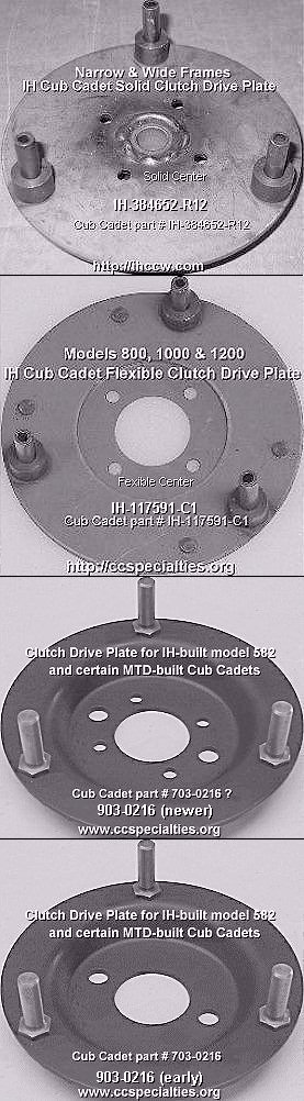 The first clutch drive plate
is designed for the IH-built narrow- and wide-frame Cub Cadet garden tractor
models 70, 71, 72, 73, 100, 102, 104, 106, 122, 124, 126, 86, 108 and 128
all with a solid-mounted engine. It's made of flat, solid/non-flexible, 1/8"
thickness steel, with a bronze bushing (pilot bearing) pressed in the center
to support the driveshaft, and have coiled/spiral
pins to drive the clutch disc. This type of drive plate can also be used
on the Cub Cadet "Quiet Line" rubber ISO-mounted engine garden tractors (listed
below Ê) as long as
solid motor mounts are installed. It's Cub
Cadet part # IH-384652-R12.
The first clutch drive plate
is designed for the IH-built narrow- and wide-frame Cub Cadet garden tractor
models 70, 71, 72, 73, 100, 102, 104, 106, 122, 124, 126, 86, 108 and 128
all with a solid-mounted engine. It's made of flat, solid/non-flexible, 1/8"
thickness steel, with a bronze bushing (pilot bearing) pressed in the center
to support the driveshaft, and have coiled/spiral
pins to drive the clutch disc. This type of drive plate can also be used
on the Cub Cadet "Quiet Line" rubber ISO-mounted engine garden tractors (listed
below Ê) as long as
solid motor mounts are installed. It's Cub
Cadet part # IH-384652-R12.
Depending on the class your tractor is going to pull in and engine size/modifications, there are many variations in which clutch/driveshaft design and carrier/axles to use. Listed are the weakest to the strongest:
Using Quality Driveshaft Material Is Important!
 Most driveshafts are likely to
break at the second coiled/spiral pin hole, just in front of the
clutch release/throw-out bearing. Because
that's where the most vibration usually occurs. They also break just behind
the pressure spring, in front of the
pillow block bearing, due to temporary
frame twisting (narrow frames) when pulling. If this happens, it's best to
install a split clamping/locking collar.
Most driveshafts are likely to
break at the second coiled/spiral pin hole, just in front of the
clutch release/throw-out bearing. Because
that's where the most vibration usually occurs. They also break just behind
the pressure spring, in front of the
pillow block bearing, due to temporary
frame twisting (narrow frames) when pulling. If this happens, it's best to
install a split clamping/locking collar.
What mainly makes the driveshaft break at 4,000+ RPM is either...
If quality driveshaft material is used, and if the rotating parts are precision balanced and if a carrier bearing is also installed (above 4,000 RPM. The factory setting of maximum RPM for virtually all small gas engines, including all of Kohler engines is 3,600), the driveshaft could possibly last the life of the tractor. Even when used in high-performance conditions.
Remember, in the direct-drive Cub Cadet garden tractor, the entire clutch/driveshaft assembly rotates the same speed as the engine. For reliability in a highly modified tractor that turns well above 4,000 RPM, the driveshaft must be made of quality, solid hardened steel that can resist torsional twist. Such as high strength 1144 stress proof steel, heat-treated 4140 chrome-moly steel or ultra tough 304 alloy stainless steel.
Advertisement: (Prices are subject to change without notice.) Click here to contact A-1 Miller's Performance Enterprises to place an order, send your parts for repairing, and/or for FREE professional and honest technical customer service assistance and support and payment options. Please contact A-1 Miller's if you need a part or parts, or service(s) performed that's not listed or mentioned in this website. | [Top of Page]
| Click here to contact A-1 Miller's Performance Enterprises to place an order, send your parts for repairing, and/or for FREE professional and honest technical customer service assistance and support and payment options. Please contact A-1 Miller's if you need a part or parts, or service(s) performed that's not listed or mentioned in this website. | [Top of Page] |
Professionally Rebuild YOUR IH Cub Cadet Original Garden Tractor Clutch Assembly. NOTE: I'll try to keep the total rebuild price reasonable, but being replacement parts for the Original clutch are hard to find nowadays, the price may be higher. $350.00± each for parts and labor, plus return shipping & handling.
Professionally Rebuild YOUR IH- or MTD-built Cub Cadet Garden Tractor Clutch Assembly. $250.00± each for parts and labor, plus return shipping & handling. Professionally Rebuilt IH- or MTD-built Cub Cadet Garden Tractor Clutch Assemblies for General Lawn and Garden Use. Includes all narrow, wide and spread frame models. When ordering, please specify model of tractor and if it has a creeper drive or not. $350.00± each, depending on model, plus return shipping & handling. Professionally Rebuilt IH- or MTD-built Cub Cadet Garden Tractor Clutch Assemblies for Heavy Duty Use or Competition Pulling. Includes all narrow, wide and spread frame models. $500.00± each, depending on model and usage, plus return shipping & handling.
|
| Cub Cadet Garden Tractor Driveshafts
- Click here to contact A-1 Miller's Performance
Enterprises to place an order, send your parts for repairing, and/or for
FREE professional and honest technical customer service assistance and support
and payment options. Please contact A-1 Miller's if you need a part or
parts, or service(s) performed that's not listed or mentioned in this website.
| [Top of Page]
Click here to contact A-1 Miller's Performance Enterprises to place an order, send your parts for repairing, and/or for FREE professional and honest technical customer service assistance and support and payment options. If you need a part or parts that's not listed in this website, please contact A-1 Miller's and we'll see if we can get it at a reasonable price. | [Top of Page]
Replacement Heavy Duty Coiled/Spiral Pins for Cub Cadet Creeper Drives, Garden Tractor Driveshafts and 3-Pin Clutch Drive Plate. Each made of high strength, heat treated, hardened carbon steel. Minimum Rockwell hardness is C42. [Return To Previous Section, Paragraph or Website]
1/4" Diameter Heavy Duty Coiled/Spiral Pins for all other models of Cub Cadet garden tractor driveshafts. 6,500 P.S.I. breaking strength. NOTE: The driveshafts with or without a creeper drive use the same number of coiled/spiral pins. There's two to drive the pressure plates (1-1/2" length), one behind the main pressure spring (1" length), and two in the tubular coupler (1" length for the small diameter coupler, or 1-1/2" length for the large diameter coupler). NOTE - On the narrow frame Cub Cadet garden tractors, a grade 8 bolt w/locknut can be used to connect the coupler to the input shaft in the transaxle for much easier installation and removal.
|
 OEM
Cub Cadet Garden Tractor 3-Pin Solid Clutch Drive Plate.
Designed for IH-built Cub Cadet garden tractor models 70, 71, 72, 73, 86,
100, 102, 104, 108, 122, 124, 126 and 128 with the solid-mounted engine.
These models have the engine fastened directly to the frame with no rubber
motor mounts. If you want to use this type of drive plate in a "Quiet Line"
model 800, 1000 or 1200 with the ISO-mounted engine, then a set of A-1 Miller's
solid motor mounts must also be installed,
making the clutch/driveshaft assembly rigid throughout so less wear will
occur to the clutch assembly. IMPORTANT: To prevent the pilot bushing
(and holes in the clutch disc) from wearing excessively, it's highly recommended
that your OEM pressure plates be trued-up (and faced (resurfaced) until perfectly
flat for better clutch adhesion) in a
metal lathe. And before reinstalling the driveshaft/clutch
assembly in the tractor, apply automotive grease inside the pilot bushing
and/or on the front of the driveshaft. Because if either is dry, chances
are, the driveshaft will wear the bushing excessively or bind up in the bushing,
and the clutch may not release. OEM
Cub Cadet Garden Tractor 3-Pin Solid Clutch Drive Plate.
Designed for IH-built Cub Cadet garden tractor models 70, 71, 72, 73, 86,
100, 102, 104, 108, 122, 124, 126 and 128 with the solid-mounted engine.
These models have the engine fastened directly to the frame with no rubber
motor mounts. If you want to use this type of drive plate in a "Quiet Line"
model 800, 1000 or 1200 with the ISO-mounted engine, then a set of A-1 Miller's
solid motor mounts must also be installed,
making the clutch/driveshaft assembly rigid throughout so less wear will
occur to the clutch assembly. IMPORTANT: To prevent the pilot bushing
(and holes in the clutch disc) from wearing excessively, it's highly recommended
that your OEM pressure plates be trued-up (and faced (resurfaced) until perfectly
flat for better clutch adhesion) in a
metal lathe. And before reinstalling the driveshaft/clutch
assembly in the tractor, apply automotive grease inside the pilot bushing
and/or on the front of the driveshaft. Because if either is dry, chances
are, the driveshaft will wear the bushing excessively or bind up in the bushing,
and the clutch may not release.
|
 Cub Cadet Garden Tractor
3-Pin Flexible Center Clutch Drive Plate. Designed for IH-built
Cub Cadet garden tractor "Quiet Line" models 800, 1000 and 1200, including
models 1250, 1450 and 1650 with a hydrostatic disconnect attachment. All
these models have a rubber ISO-mounted engine to
reduce vibration throughout the tractor for operator comfort. IMPORTANT
- To maintain balance of this particular drive plate, one spiral pin is longer
than the other two - do not grind it down! And both pressure plates should
be trued-up (and faced (resurfaced) until perfectly flat for better clutch
adhesion) in a metal lathe to prevent the possibility of breakage. FYI -
The OEM Cub Cadet clutch pressure plates are made of stamped steel, which
makes them somewhat oblong or "egg-shaped" and not machined perfectly round,
which cause the clutch disc and drive plate to wear and eventually break.
This is what cause the pilot bushing to prematurely wear. And before reinstalling
the driveshaft/clutch assembly in the tractor, apply automotive grease inside
the pilot bushing and/or on the front of the driveshaft. Because if either
is dry, chances are, the driveshaft can bind up in the bushing, the clutch
may not release, and cause severe wear to both the bushing and driveshaft.
Replaces discontinued Cub Cadet flexible drive plate part # IH-106545-C93. Cub Cadet Garden Tractor
3-Pin Flexible Center Clutch Drive Plate. Designed for IH-built
Cub Cadet garden tractor "Quiet Line" models 800, 1000 and 1200, including
models 1250, 1450 and 1650 with a hydrostatic disconnect attachment. All
these models have a rubber ISO-mounted engine to
reduce vibration throughout the tractor for operator comfort. IMPORTANT
- To maintain balance of this particular drive plate, one spiral pin is longer
than the other two - do not grind it down! And both pressure plates should
be trued-up (and faced (resurfaced) until perfectly flat for better clutch
adhesion) in a metal lathe to prevent the possibility of breakage. FYI -
The OEM Cub Cadet clutch pressure plates are made of stamped steel, which
makes them somewhat oblong or "egg-shaped" and not machined perfectly round,
which cause the clutch disc and drive plate to wear and eventually break.
This is what cause the pilot bushing to prematurely wear. And before reinstalling
the driveshaft/clutch assembly in the tractor, apply automotive grease inside
the pilot bushing and/or on the front of the driveshaft. Because if either
is dry, chances are, the driveshaft can bind up in the bushing, the clutch
may not release, and cause severe wear to both the bushing and driveshaft.
Replaces discontinued Cub Cadet flexible drive plate part # IH-106545-C93.
|
  A-1 Miller's Professional Repair Service - Weld Spiral
Pin Collars on YOUR OEM IH Cub Cadet Garden Tractor Drive Plate. This adds
approximately 85% more strength to prevent from bending or flexing of drive
plate while under severe strain from heavy duty use or competition pulling.
Labor include true-up drive plate in
metal lathe to remove wobble or run-out to reduce vibration.
We always perform this repair to a customer's drive plate, as part of the
complete clutch rebuild. IMPORTANT: To prevent the pilot bushing (and
holes in the clutch disc) from wearing excessively, it's highly recommended
that your OEM pressure plates be trued-up (and faced (resurfaced) until perfectly
flat for better clutch adhesion) in a
metal lathe. And before reinstalling the driveshaft/clutch
assembly in the tractor, apply automotive grease inside the pilot bushing
and/or on the front of the driveshaft. Because if either is dry, chances
are, the driveshaft will wear the bushing excessively or bind up in the bushing,
and the clutch may not release. A-1 Miller's Professional Repair Service - Weld Spiral
Pin Collars on YOUR OEM IH Cub Cadet Garden Tractor Drive Plate. This adds
approximately 85% more strength to prevent from bending or flexing of drive
plate while under severe strain from heavy duty use or competition pulling.
Labor include true-up drive plate in
metal lathe to remove wobble or run-out to reduce vibration.
We always perform this repair to a customer's drive plate, as part of the
complete clutch rebuild. IMPORTANT: To prevent the pilot bushing (and
holes in the clutch disc) from wearing excessively, it's highly recommended
that your OEM pressure plates be trued-up (and faced (resurfaced) until perfectly
flat for better clutch adhesion) in a
metal lathe. And before reinstalling the driveshaft/clutch
assembly in the tractor, apply automotive grease inside the pilot bushing
and/or on the front of the driveshaft. Because if either is dry, chances
are, the driveshaft will wear the bushing excessively or bind up in the bushing,
and the clutch may not release.
|
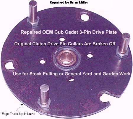 A-1 Miller's Professional
Repair Service - Repair your OEM IH Cub Cadet garden tractor 3-pin clutch
drive plate when the three OEM drive pin collar(s) are broken off with three
hardened steel drive studs. No need to purchase another drive plate. Work
include true-up drive plate in
metal lathe to remove wobble or run-out to reduce vibration
and for precision alignment installation of drive studs. I can also do this
to repair a customer's drive plate, as part of the clutch rebuild. Three
new holes drilled precisely at 2.5625" from dead center on a milling machine
with a super indexing spacer. IMPORTANT: To prevent the pilot bushing
(and holes in the clutch disc) from wearing excessively, it's highly recommended
that your OEM pressure plates be trued-up (and faced (resurfaced) until perfectly
flat for better clutch adhesion) in a
metal lathe. And before reinstalling the driveshaft/clutch
assembly in the tractor, apply automotive grease inside the pilot bushing
and/or on the front of the driveshaft. Because if either is dry, chances
are, the driveshaft will wear the bushing excessively or bind up in the bushing,
and the clutch may not release.
A-1 Miller's Professional
Repair Service - Repair your OEM IH Cub Cadet garden tractor 3-pin clutch
drive plate when the three OEM drive pin collar(s) are broken off with three
hardened steel drive studs. No need to purchase another drive plate. Work
include true-up drive plate in
metal lathe to remove wobble or run-out to reduce vibration
and for precision alignment installation of drive studs. I can also do this
to repair a customer's drive plate, as part of the clutch rebuild. Three
new holes drilled precisely at 2.5625" from dead center on a milling machine
with a super indexing spacer. IMPORTANT: To prevent the pilot bushing
(and holes in the clutch disc) from wearing excessively, it's highly recommended
that your OEM pressure plates be trued-up (and faced (resurfaced) until perfectly
flat for better clutch adhesion) in a
metal lathe. And before reinstalling the driveshaft/clutch
assembly in the tractor, apply automotive grease inside the pilot bushing
and/or on the front of the driveshaft. Because if either is dry, chances
are, the driveshaft will wear the bushing excessively or bind up in the bushing,
and the clutch may not release.
|
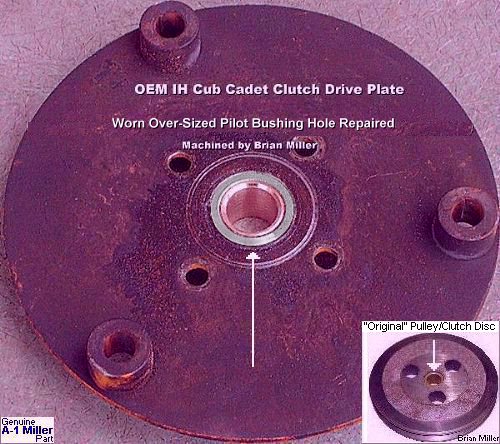 A-1 Miller's Professional Repair Service - Repair Worn
Over-Size Pilot Bushing Hole in YOUR IH Cub Cadet Garden Tractor Drive Plate,
or Repair Bushing in YOUR Cub Cadet "Original" Garden Tractor Pulley/Clutch
Disc for Installation of OEM-size Pilot Bushing. No need to purchase another
drive plate. Work include true-up drive plate in
metal lathe to remove wobble or run-out to reduce vibration.
I can also do this to repair a customer's drive plate, as part of the clutch
rebuild. Work is performed in a large metal lathe. IMPORTANT: To prevent
the pilot bushing (and holes in the clutch disc) from wearing excessively,
it's highly recommended that your OEM pressure plates be trued-up (and faced
(resurfaced) until perfectly flat for better clutch adhesion) in a
metal lathe. And before reinstalling the driveshaft/clutch
assembly in the tractor, apply automotive grease inside the pilot bushing
and/or on the front of the driveshaft. Because if either is dry, chances
are, the driveshaft will wear the bushing excessively or bind up in the bushing,
and the clutch may not release. A-1 Miller's Professional Repair Service - Repair Worn
Over-Size Pilot Bushing Hole in YOUR IH Cub Cadet Garden Tractor Drive Plate,
or Repair Bushing in YOUR Cub Cadet "Original" Garden Tractor Pulley/Clutch
Disc for Installation of OEM-size Pilot Bushing. No need to purchase another
drive plate. Work include true-up drive plate in
metal lathe to remove wobble or run-out to reduce vibration.
I can also do this to repair a customer's drive plate, as part of the clutch
rebuild. Work is performed in a large metal lathe. IMPORTANT: To prevent
the pilot bushing (and holes in the clutch disc) from wearing excessively,
it's highly recommended that your OEM pressure plates be trued-up (and faced
(resurfaced) until perfectly flat for better clutch adhesion) in a
metal lathe. And before reinstalling the driveshaft/clutch
assembly in the tractor, apply automotive grease inside the pilot bushing
and/or on the front of the driveshaft. Because if either is dry, chances
are, the driveshaft will wear the bushing excessively or bind up in the bushing,
and the clutch may not release.
|
| A-1 Miller's Professional
Repair Service - Convert your OEM IH or MTD Cub Cadet garden tractor
clutch drive plate from 3-pin (IH) or 3-stud (MTD) to 3-pin/3-stud or 6-stud.
Work includes true-up plate in
metal lathe to remove wobble or run-out to reduce vibration,
drill three new holes precisely at 2.5625" from dead center on a milling
machine with a super indexing spacer to match OEM pins or studs, and then
install 3 additional hardened steel studs, lock washers and nuts. I can also
do this to repair a customer's drive plate, as part of the clutch rebuild.
NOTE: Clutch disc must be precision-drilled with 3 additional holes to
accept the 3 additional drive studs. IMPORTANT: To prevent the pilot bushing
(and holes in the clutch disc) from wearing excessively, it's highly recommended
that your OEM pressure plates be trued-up (and faced (resurfaced) until perfectly
flat for better clutch adhesion) in a
metal lathe. And before reinstalling the driveshaft/clutch
assembly in the tractor, apply automotive grease inside the pilot bushing
and/or on the front of the driveshaft. Because if either is dry, chances
are, the driveshaft will wear the bushing excessively or bind up in the bushing,
and the clutch may not release. $60.00 each drive plate, includes
parts and labor, plus return shipping & handling.
|
 Heavy Duty 6-Pin x 1/8"
Thickness Clutch Drive Plate. Made with hardened steel studs. Can be
used with 6 hole composite or metallic clutch disc, or three pins can be
removed for use with a 3 hole clutch disc. Fits IH- and MTD-built Cub Cadet
garden tractors with OEM Cub Cadet clutch disc, aftermarket composite clutch
disc or aftermarket metallic clutch disc. Designed for heavy yard and garden
use, snow blowing or open RPM competition pulling
(pillow block bearing and brace also
recommended). Holes for all six drive studs drilled precisely at 2.5625"
from dead center on a milling machine with a super indexing spacer to match
drive holes in OEM Cub Cadet clutch disc or billet aluminum clutch disc.
NOTE: To prevent damage to the clutch assembly, when used in a Cub Cadet
"Quiet Line" model 800, 1000 or 1200, solid motor
mounts must also be installed. And the 3 hole clutch disc must be
precision-drilled with 3 additional holes precision aligned drilled to accept
the 3 additional drive studs in this 6-pin plate. IMPORTANT: To prevent the
pilot bushing (and holes in the clutch disc) from wearing excessively, it's
highly recommended that your OEM pressure plates be trued-up (and faced
(resurfaced) until perfectly flat for better clutch adhesion) in a
metal lathe with a 3 jaw chuck. Also, before reinstalling
the driveshaft/clutch assembly in the tractor, apply automotive grease inside
the pilot bushing and/or on the front of the driveshaft. Because if either
is dry, chances are, the driveshaft will wear the bushing excessively or
bind up in the bushing, and the clutch may not release. $105.00
each, plus shipping & handling. Heavy Duty 6-Pin x 1/8"
Thickness Clutch Drive Plate. Made with hardened steel studs. Can be
used with 6 hole composite or metallic clutch disc, or three pins can be
removed for use with a 3 hole clutch disc. Fits IH- and MTD-built Cub Cadet
garden tractors with OEM Cub Cadet clutch disc, aftermarket composite clutch
disc or aftermarket metallic clutch disc. Designed for heavy yard and garden
use, snow blowing or open RPM competition pulling
(pillow block bearing and brace also
recommended). Holes for all six drive studs drilled precisely at 2.5625"
from dead center on a milling machine with a super indexing spacer to match
drive holes in OEM Cub Cadet clutch disc or billet aluminum clutch disc.
NOTE: To prevent damage to the clutch assembly, when used in a Cub Cadet
"Quiet Line" model 800, 1000 or 1200, solid motor
mounts must also be installed. And the 3 hole clutch disc must be
precision-drilled with 3 additional holes precision aligned drilled to accept
the 3 additional drive studs in this 6-pin plate. IMPORTANT: To prevent the
pilot bushing (and holes in the clutch disc) from wearing excessively, it's
highly recommended that your OEM pressure plates be trued-up (and faced
(resurfaced) until perfectly flat for better clutch adhesion) in a
metal lathe with a 3 jaw chuck. Also, before reinstalling
the driveshaft/clutch assembly in the tractor, apply automotive grease inside
the pilot bushing and/or on the front of the driveshaft. Because if either
is dry, chances are, the driveshaft will wear the bushing excessively or
bind up in the bushing, and the clutch may not release. $105.00
each, plus shipping & handling. |
  Clutch Drive Studs w/nuts and split lock washers for Cub
Cadet garden tractors. IMPORTANT: Installing three additional
clutch drive stud in a drive plate is something that must be performed with
precision accuracy. And it's highly recommended that your OEM pressure
plates be trued-up in a
metal lathe (with a self-centering 3-jaw chuck) so they'll
be perfectly round (to reduce premature pilot bushing wear, and faced
(resurfaced) until perfectly flat for better clutch adhesion) to prevent
premature wearing of the new pilot bushing and drive pins in the drive plate,
and holes in the clutch disc. Clutch Drive Studs w/nuts and split lock washers for Cub
Cadet garden tractors. IMPORTANT: Installing three additional
clutch drive stud in a drive plate is something that must be performed with
precision accuracy. And it's highly recommended that your OEM pressure
plates be trued-up in a
metal lathe (with a self-centering 3-jaw chuck) so they'll
be perfectly round (to reduce premature pilot bushing wear, and faced
(resurfaced) until perfectly flat for better clutch adhesion) to prevent
premature wearing of the new pilot bushing and drive pins in the drive plate,
and holes in the clutch disc.
|
 Do this only if the front
axle have been moved forward -
Do this only if the front
axle have been moved forward -
 On the narrow frame Cub Cadet garden tractors, if the front
axle have been moved forward, reinforce the frame rails where the engine
mounting holes are to reduce normal high-RPM engine vibration travel that
could lead to both frame and driveshaft breakage. To do so, stiffen the frame
rails where the engine mounting bolt holes are by welding two 1/4" thick
steel plates under the frame. Longer engine mounting bolts must be used,
too. The reason for this is because when the front axle center support is
moved, the remaining frame material isn't thick enough to hold up to the
engine vibration.
On the narrow frame Cub Cadet garden tractors, if the front
axle have been moved forward, reinforce the frame rails where the engine
mounting holes are to reduce normal high-RPM engine vibration travel that
could lead to both frame and driveshaft breakage. To do so, stiffen the frame
rails where the engine mounting bolt holes are by welding two 1/4" thick
steel plates under the frame. Longer engine mounting bolts must be used,
too. The reason for this is because when the front axle center support is
moved, the remaining frame material isn't thick enough to hold up to the
engine vibration.
For the spread frame models with the ISO (rubber) motor mounts, replace the rubber mounts with a set of our solid steel motor mounts or remove the brackets and fabricate a minimum 1/4" thick plate steel, set it at the right height and weld it to the frame. But the engine mounting holes and oil drain plug hole must be properly located (centered) and drilled in the plate first. This is much easier to do on a platform work table than on the floor or ground. [Return to Previous Section, Paragraph or Website]
|
|
|
|
|
|
How to Remove the Driveshaft/Clutch Assembly from a Cub Cadet Garden Tractor: (This is much easier performed on a platform work table than on the floor or ground.) (Updated 9/13/22)
The coiled/spiral pin in
the input shaft on the transaxle of a narrow frame Cub Cadet garden tractor
can be very difficult to remove and somewhat difficult to access from underneath.
Therefore, it's recommended that a 1" hole should be drilled through the
top of a short tunnel cover (center section of the tractor frame), or through
the side of a tall tunnel cover in direct alignment with the coiled/spiral
pin, then use a long 1/4" roll pin punch and medium size hammer to drive
the pin from the coupler. Don't attempt to drill-out the coiled/spiral pin.
They're just as hard as a high quality drill bit. After the pin is removed
and the clutch assembly is rebuilt, upon reinstallation in the tractor, use
a socket in the drilled hole to fasten a hardened steel 1/4" diameter
[grade 8 or Allen head] bolt in the coupler.
 For cosmetic purpose, hide the drilled hole with a 1" plastic
or metal hole plug. Just push the plug in the hole for a nice distinctive
look. And sometimes when driving out the coiled/spiral pin, the pounding
will bend the input shaft in the transaxle. If this happens, the input shaft
will need to be straightened (and hope it doesn't break later because the
metal have been weakened) or a good used input shaft will need to be installed.
This is why it's highly recommended that a hardened steel (grade 8) 1/4"
bolt/lock nut be used in the coupler in place of the coiled/spiral pin because
if the driveshaft ever needs to be removed again, removing a bolt/lock nut
would be a lot easier than driving out a stubborn coiled/spiral pin. Plus,
it'll be easier on your nerves and on the input shaft.
For cosmetic purpose, hide the drilled hole with a 1" plastic
or metal hole plug. Just push the plug in the hole for a nice distinctive
look. And sometimes when driving out the coiled/spiral pin, the pounding
will bend the input shaft in the transaxle. If this happens, the input shaft
will need to be straightened (and hope it doesn't break later because the
metal have been weakened) or a good used input shaft will need to be installed.
This is why it's highly recommended that a hardened steel (grade 8) 1/4"
bolt/lock nut be used in the coupler in place of the coiled/spiral pin because
if the driveshaft ever needs to be removed again, removing a bolt/lock nut
would be a lot easier than driving out a stubborn coiled/spiral pin. Plus,
it'll be easier on your nerves and on the input shaft.
 On the IH-built models 800, 1000
and 1200, there's a 5/8" steel ball at the end of the driveshaft located
inside the rear flex arm coupler (with the bronze swivel bushing). Do not
lose this ball! It will need to be reused when reinstalling the clutch
assembly/driveshaft in the tractor. This ball is located at the end of
the driveshaft and inside the rear flex arm coupler (with the bronze swivel
bushing) and sometimes gets lost when removing the clutch assembly/driveshaft
from the tractor. It allows the driveshaft to "move side to side" with the
engine (that's mounted on rubber mounts). If it's left out, the clutch
assembly/driveshaft will move further back 5/8" when the clutch pedal is
depressed, and the clutch disc will not release and operate correctly. The
MTD-built models have no steel ball. The end of the [5/8" longer] driveshaft
is pointed, which fits in the pilot hole of the input shaft in the
transaxle.
On the IH-built models 800, 1000
and 1200, there's a 5/8" steel ball at the end of the driveshaft located
inside the rear flex arm coupler (with the bronze swivel bushing). Do not
lose this ball! It will need to be reused when reinstalling the clutch
assembly/driveshaft in the tractor. This ball is located at the end of
the driveshaft and inside the rear flex arm coupler (with the bronze swivel
bushing) and sometimes gets lost when removing the clutch assembly/driveshaft
from the tractor. It allows the driveshaft to "move side to side" with the
engine (that's mounted on rubber mounts). If it's left out, the clutch
assembly/driveshaft will move further back 5/8" when the clutch pedal is
depressed, and the clutch disc will not release and operate correctly. The
MTD-built models have no steel ball. The end of the [5/8" longer] driveshaft
is pointed, which fits in the pilot hole of the input shaft in the
transaxle.
How to Disassemble the Clutch Components from the Driveshaft -
To disassemble the clutch components from the driveshaft, first place the front pressure plate hub on slightly open jaws of a bench vise, and use a quality-made 1/4" coiled/spiral pin punch and a medium size hammer to drive out the coiled/spiral pin. Then the pressure plates, clutch disc clutch release/throw-out bearing and pressure spring should all slide off the driveshaft.
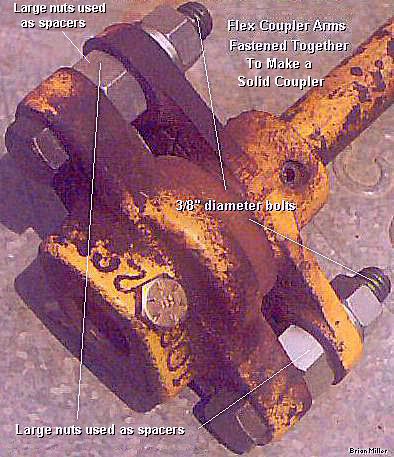
Fasten the Coupler Arms Together To Make One Rigid Driveshaft Coupler -
 With solid
motor mounts installed in a Cub Cadet "Quiet Line" garden tractor that
originally came with a rubber ISO-mounted engine, the driveshaft will not
be able to "move" with the engine and there'll be less chance of clutch parts
prematurely wearing or breaking. The flexible rubber disc(s) at the end of
the driveshaft will be useless too, and could deteriorate over time. So instead
of replacing the OEM coupler arms with a machined rigid tubular coupler,
make the coupler arms rigid by removing the flexible rubber disc(s) and install
a couple of 3/8" thickness spacers for a single disc, and a couple of 3/4"
thickness spacers for double composite clutch discs, and fasten the arms
together with a couple of 3/8" diameter hardened steel bolts. (Large nuts
are used as spacers in the photo to the right.) By the way - one rubber flex
disc is 3/8" thick. This setup is just as strong as using a rigid tubular
coupler, and it cost a lot less.
With solid
motor mounts installed in a Cub Cadet "Quiet Line" garden tractor that
originally came with a rubber ISO-mounted engine, the driveshaft will not
be able to "move" with the engine and there'll be less chance of clutch parts
prematurely wearing or breaking. The flexible rubber disc(s) at the end of
the driveshaft will be useless too, and could deteriorate over time. So instead
of replacing the OEM coupler arms with a machined rigid tubular coupler,
make the coupler arms rigid by removing the flexible rubber disc(s) and install
a couple of 3/8" thickness spacers for a single disc, and a couple of 3/4"
thickness spacers for double composite clutch discs, and fasten the arms
together with a couple of 3/8" diameter hardened steel bolts. (Large nuts
are used as spacers in the photo to the right.) By the way - one rubber flex
disc is 3/8" thick. This setup is just as strong as using a rigid tubular
coupler, and it cost a lot less.
If the outer parts of the
two arms don't come together or meet when the bolts are tightened (be careful
not to tighten the bolts too tight if the arms don't meet, they could break),
a couple of thin flat washers may need to be added as shims next to the spacers.
And before fastening the arms together with the spacers, first slide the
arms on the driveshaft so they'll be in perfect alignment with each other,
and tighten the bolts. See the photo to the right ->. Also, if you want,
leave out the 5/8" diameter [swivel/spacer] steel ball. It'll serve no purpose
when using solid motor mounts and when making
the coupler arms rigid.
FYI - Many pullers convert the hydrostatic drive Cub Cadet garden tractor models 109, 129, 149 and 169 (wide frames with a solid mounted engine) and models 1250, 1450 and 1650 (wide frames with a rubber ISO-mounted engine) into a clutch drive tractor. All that's needed are the clutch assembly with the hanger support bracket for the release lever and a complete transaxle out of a gear drive Cub Cadet garden tractor model 86, 108, 128 (wide frames with a solid mounted engine) or models 800, 1000 or 1200 (wide frames with a rubber ISO-mounted engine). A set of A-1 Miller's solid motor mounts will be also be needed if the tractor originally have the ISO rubber motor mounts. The braking mechanism, preferably the internal "wet" brake, out of a wide frame Cub Cadet garden tractor will also be needed.
Do not fasten the two coupler
arms directly together on the IH Cub Cadet "Original" garden tractor because
the driveshaft needs to move up or down to tighten the drive belt with the
engine. Leave the flexible rubber disc in place, even for pulling competition.
Or a 5/8" I.D. universal joint can be installed instead.
 A rigid tubular rear driveshaft coupler with a worn center
can be repaired by boring out the center and installing a press-fit steel
sleeve. Then ream the sleeve to .626" (16mm) for a slip-fit on the driveshaft.
Then the holes for the coiled/spiral pins
can be drilled. The boring and reaming process should be performed on
a
milling machine with a
super indexing spacer or in a
metal lathe with a self-centering 3-jaw chuck.
(IMPORTANT: If you don't feel comfortable using
a metal lathe, please consult a professional and experienced machinist with
a lathe.)
A rigid tubular rear driveshaft coupler with a worn center
can be repaired by boring out the center and installing a press-fit steel
sleeve. Then ream the sleeve to .626" (16mm) for a slip-fit on the driveshaft.
Then the holes for the coiled/spiral pins
can be drilled. The boring and reaming process should be performed on
a
milling machine with a
super indexing spacer or in a
metal lathe with a self-centering 3-jaw chuck.
(IMPORTANT: If you don't feel comfortable using
a metal lathe, please consult a professional and experienced machinist with
a lathe.)
 Installing a coiled/spiral pin in the rear of the driveshaft
to connect the coupler to the input shaft on the transaxle of a Cub Cadet
garden tractor can be very difficult. To make it much easier, simply use
a 1/4" grade 8 bolt instead. For strength, the shank (unthreaded part) of
the bolt needs to have full contact with the coupler and driveshaft. And
as long as the driveshaft is in correct alignment with the centerline of
the crankshaft and transaxle input shaft, with the coiled/spiral pin holes
in-line with each other, and not offset 90°, at around 4,000 RPM, this
should not cause the driveshaft to "shake around" or vibrate whatsoever.
At high RPM or at
wide
open throttle, a center support pillow
block bearing and brace should be used midway on the driveshaft.
Installing a coiled/spiral pin in the rear of the driveshaft
to connect the coupler to the input shaft on the transaxle of a Cub Cadet
garden tractor can be very difficult. To make it much easier, simply use
a 1/4" grade 8 bolt instead. For strength, the shank (unthreaded part) of
the bolt needs to have full contact with the coupler and driveshaft. And
as long as the driveshaft is in correct alignment with the centerline of
the crankshaft and transaxle input shaft, with the coiled/spiral pin holes
in-line with each other, and not offset 90°, at around 4,000 RPM, this
should not cause the driveshaft to "shake around" or vibrate whatsoever.
At high RPM or at
wide
open throttle, a center support pillow
block bearing and brace should be used midway on the driveshaft.
For pulling applications, rubber motor mounts (and the flexible coupler at the rear of the driveshaft) absorbs valuable horsepower, which must be transferred to the rear tires for full power to the track. The rubber motor mounts will also cause the engine to vibrate excessively at high RPM or at wide open throttle. Plus, with normal use of the tractor, rubber motor mounts could cause the flexible 3-pin drive plate and/or the driveshaft to eventually break. If a tractor that have rubber motor mounts and a flexible coupler is going to be used for competition pulling, definitely install some metal motor mounts.
First of all, when using a milling machine, use a spotting drill bit, or use a center punch or transfer punch to locate exactly where the hole needs to be drilled to prevent the drill bit from "skating" on the surface. This will position and guide the drill bit to bore EXACTLY where the hole needs to be drilled. And due to the natural expansion of a roll, coiled or coiled/spiral pin, ALWAYS drill the hole with a drill bit that's one size smaller than the actual size for the roll, coiled or coiled/spiral pin's size, to allow for sufficient compression of the pin when installed in the hole. For example: for a 1/4" roll, coiled or coiled/spiral pin, initially drill the hole with a 15/64" drill bit (one size smaller than the 1/4" drill bit), then finish enlarging the same hole with a 1/4" drill bit. Doing this will guarantee the hole will be EXACTLY 1/4" in diameter. If the hole is initially drilled with just the 1/4" bit, chances are, this will cause the hole to be wallowed out, making it too big for the 1/4" roll, coiled or coiled/spiral pin. [Return to Previous Section, Paragraph or Website]
Advertisement: (Prices are subject to change without notice.) Click here to contact A-1 Miller's Performance Enterprises to place an order, send your parts for repairing, and/or for FREE professional and honest technical customer service assistance and support and payment options. Please contact A-1 Miller's if you need a part or parts, or service(s) performed that's not listed or mentioned in this website. | [Top of Page]
| Solid Motor Mount Kit for Cub
Cadet "Quiet Line" Garden Tractors. Replace OEM Rubber ISO-Mounts with a
Set of Solid Motor Mounts to Prevent Repeated and Costly Damage to the Clutch
Components! [Top of Page]
Details include:
|
|||
 OEM-Thickness
Bronze Pilot Bushing. Fits all pre-1981 gear drive IH-built Cub Cadet garden
tractor models 70, 71, 72, 73, 86, 100, 102, 104, 106, 108, 122, 124, 126
and 128, except "Quiet Line" models. This is also the replacement bushing
for the IH Cub Cadet "Original" garden tractor pulley/clutch disc. Dimensions:
5/8" I.D. x 7/8" O.D. x 3/4" length. IMPORTANT: To prevent the replacement
pilot bushing from premature wear, both OEM pressure plates should be trued-up
in a
metal lathe (with a self-centering 3-jaw chuck) so they'll
be perfectly round (to reduce premature pilot bushing wear, and faced
(resurfaced) until perfectly flat for better clutch adhesion), and before
reinstalling the driveshaft/clutch assembly in the tractor, apply automotive
grease inside the pilot bushing and/or on the front of the driveshaft. Because
if the bushing is dry, chances are, the driveshaft can bind up in the bushing,
the clutch may not release, and cause severe wear to both the bushing and
driveshaft. OEM-Thickness
Bronze Pilot Bushing. Fits all pre-1981 gear drive IH-built Cub Cadet garden
tractor models 70, 71, 72, 73, 86, 100, 102, 104, 106, 108, 122, 124, 126
and 128, except "Quiet Line" models. This is also the replacement bushing
for the IH Cub Cadet "Original" garden tractor pulley/clutch disc. Dimensions:
5/8" I.D. x 7/8" O.D. x 3/4" length. IMPORTANT: To prevent the replacement
pilot bushing from premature wear, both OEM pressure plates should be trued-up
in a
metal lathe (with a self-centering 3-jaw chuck) so they'll
be perfectly round (to reduce premature pilot bushing wear, and faced
(resurfaced) until perfectly flat for better clutch adhesion), and before
reinstalling the driveshaft/clutch assembly in the tractor, apply automotive
grease inside the pilot bushing and/or on the front of the driveshaft. Because
if the bushing is dry, chances are, the driveshaft can bind up in the bushing,
the clutch may not release, and cause severe wear to both the bushing and
driveshaft.
|
|||
 Thin-Wall Bronze
Pilot Bushing Insert for installing inside a worn OEM bronze pilot bushing
in all pre-1981 gear drive IH Cub Cadet garden tractor models 70, 71, 72,
73, 86, 100, 102, 104, 106, 108, 122, 124, 126 and 128, except "Quiet Line"
models. Can also be used inside the OEM bushing in the IH Cub Cadet "Original"
garden tractor pulley/clutch disc. Dimensions: 5/8" I.D. x 3/4" O.D. x 3/4"
length. NOTE: Worn OEM bushing must be precision center-bored to .750"
in a
metal lathe (with a self-centering 3-jaw chuck) so this
bushing will have a press fit. IMPORTANT: To prevent the replacement pilot
bushing from premature wear, both OEM pressure plates should be faced
(resurfaced) and trued-up in a metal lathe (with a self-centering 3-jaw chuck)
so they'll be perfectly round (to reduce premature pilot bushing wear, and
faced (resurfaced) until perfectly flat for better clutch adhesion), and
before reinstalling the driveshaft/clutch assembly in the tractor, apply
automotive grease inside the pilot bushing and/or on the front of the driveshaft.
Because if the bushing is dry, chances are, the driveshaft can bind up in
the bushing, the clutch may not release, and cause severe wear to both the
bushing and driveshaft. $3.00 each, plus shipping & handling. Thin-Wall Bronze
Pilot Bushing Insert for installing inside a worn OEM bronze pilot bushing
in all pre-1981 gear drive IH Cub Cadet garden tractor models 70, 71, 72,
73, 86, 100, 102, 104, 106, 108, 122, 124, 126 and 128, except "Quiet Line"
models. Can also be used inside the OEM bushing in the IH Cub Cadet "Original"
garden tractor pulley/clutch disc. Dimensions: 5/8" I.D. x 3/4" O.D. x 3/4"
length. NOTE: Worn OEM bushing must be precision center-bored to .750"
in a
metal lathe (with a self-centering 3-jaw chuck) so this
bushing will have a press fit. IMPORTANT: To prevent the replacement pilot
bushing from premature wear, both OEM pressure plates should be faced
(resurfaced) and trued-up in a metal lathe (with a self-centering 3-jaw chuck)
so they'll be perfectly round (to reduce premature pilot bushing wear, and
faced (resurfaced) until perfectly flat for better clutch adhesion), and
before reinstalling the driveshaft/clutch assembly in the tractor, apply
automotive grease inside the pilot bushing and/or on the front of the driveshaft.
Because if the bushing is dry, chances are, the driveshaft can bind up in
the bushing, the clutch may not release, and cause severe wear to both the
bushing and driveshaft. $3.00 each, plus shipping & handling. |
|||
  Tubular Driveshaft Couplers. Available in OEM stock
length, 1" longer than stock length (to lessen driveshaft wobble) or 3" rigid
tubular carbon steel driveshaft one-piece rigid tubular coupler. For a
custom-length coupler, exact locations where the coiled/spiral pin holes
need to be drilled are required. Custom-length rigid tubular driveshaft couplers,
up to 6" length are available. To find the location of the coiled/spiral
pin holes, install the driveshaft in the tractor with the engine fastened
to the frame with a couple of bolts, make sure the clutch disc is midway
on the drive pins, then measure precisely from the rear coiled/spiral pin
hole on the driveshaft to the coiled/spiral pin hole in the input shaft in
the transaxle, then add 3/4" for the overall length of the coupler. And one-piece
couplers to replace rubber flex coupler disc and coupler arms on AQS (Quiet
Line) Cub Cadet garden tractor models 800, 1000, 1050 and 1200 when using
solid motor mounts. The 800, 1000 and 1200
coupler will come with two roll pin holes for single or double rubber flex
coupler(s). NOTE: The 3" aftermarket coupler is
used only for competition pulling tractors with a shortened driveshaft so
the input shaft/pinion drive gear can be changed to vary the ground speed
of the tractor. And when ordering, please specify model of Cub Cadet garden
tractor, overall length and coiled/spiral pin hole locations. Tubular Driveshaft Couplers. Available in OEM stock
length, 1" longer than stock length (to lessen driveshaft wobble) or 3" rigid
tubular carbon steel driveshaft one-piece rigid tubular coupler. For a
custom-length coupler, exact locations where the coiled/spiral pin holes
need to be drilled are required. Custom-length rigid tubular driveshaft couplers,
up to 6" length are available. To find the location of the coiled/spiral
pin holes, install the driveshaft in the tractor with the engine fastened
to the frame with a couple of bolts, make sure the clutch disc is midway
on the drive pins, then measure precisely from the rear coiled/spiral pin
hole on the driveshaft to the coiled/spiral pin hole in the input shaft in
the transaxle, then add 3/4" for the overall length of the coupler. And one-piece
couplers to replace rubber flex coupler disc and coupler arms on AQS (Quiet
Line) Cub Cadet garden tractor models 800, 1000, 1050 and 1200 when using
solid motor mounts. The 800, 1000 and 1200
coupler will come with two roll pin holes for single or double rubber flex
coupler(s). NOTE: The 3" aftermarket coupler is
used only for competition pulling tractors with a shortened driveshaft so
the input shaft/pinion drive gear can be changed to vary the ground speed
of the tractor. And when ordering, please specify model of Cub Cadet garden
tractor, overall length and coiled/spiral pin hole locations.
|
|||
| IMPORTANT: To prevent either replacement pilot bushing listed below from wearing prematurely, for clutch drive tractors, both pressure plates should be trued-up and faced (resurfaced) in a metal lathe (with a self-centering 3-jaw chuck) so they'll be perfectly round and flat (for better clutch adhesion). And before reinstalling the driveshaft/clutch assembly in the tractor, apply automotive chassis or wheel bearing grease inside the pilot bushing and/or on the front of the driveshaft. Because if the bushing or driveshaft is dry, chances are, the driveshaft can bind up in the bushing, the clutch may not release, and cause severe wear to both the bushing and driveshaft. | |||
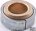 Replacement
Self-Aligning Spherical Bronze Bushing w/Outer Steel Race/Retainer. Fits
pilot bushing retainers listed below and input shaft coupler arm further
below in Cub Cadet "Quiet Line" rubber
ISO-mounted engine garden tractor models 482, 580, 582, 582 Special,
680, 682, 782, 782D, 784, 800, 882, 982, 984, 1000, 1050, 1200, 1204, 1210,
1211, 1250, 1282, 1450, 1512, 1541, 1572, 1604, 1606, 1650, 1710, 1711, 1712,
1772, 1806, 1810, 1811, 1860, 1872, 1912, 1914 and 2072. Install with hammer
and socket. OEM Cub Cadet part # 941-3004. $52.00 each, plus shipping
& handling. Replacement
Self-Aligning Spherical Bronze Bushing w/Outer Steel Race/Retainer. Fits
pilot bushing retainers listed below and input shaft coupler arm further
below in Cub Cadet "Quiet Line" rubber
ISO-mounted engine garden tractor models 482, 580, 582, 582 Special,
680, 682, 782, 782D, 784, 800, 882, 982, 984, 1000, 1050, 1200, 1204, 1210,
1211, 1250, 1282, 1450, 1512, 1541, 1572, 1604, 1606, 1650, 1710, 1711, 1712,
1772, 1806, 1810, 1811, 1860, 1872, 1912, 1914 and 2072. Install with hammer
and socket. OEM Cub Cadet part # 941-3004. $52.00 each, plus shipping
& handling. |
 Round Retainer
with Pressed-In Self-Aligning Spherical Pilot Bushing. Fits Cub Cadet "Quiet
Line" rubber ISO-mounted engine garden tractor
models 800, 1000, 1200, 1250, 1450 and 1650. OEM Cub Cadet IH-126205-C2.
$141.00 each, plus shipping & handling. Round Retainer
with Pressed-In Self-Aligning Spherical Pilot Bushing. Fits Cub Cadet "Quiet
Line" rubber ISO-mounted engine garden tractor
models 800, 1000, 1200, 1250, 1450 and 1650. OEM Cub Cadet IH-126205-C2.
$141.00 each, plus shipping & handling. |
||
 Rectangular Flange with
Pressed-In Self-Aligning Spherical Bronze Pilot Bushing. Fits Cub Cadet "Quiet
Line" rubber ISO-mounted engine garden tractor
models 680, 682, 782, 784, 1204, 1210, 1211, 1250, 1282, 1450, 1541, 1650,
1710, 1711, 1712, 1810, 1811, 1812, 1860, 1872 and 2072. OEM Cub Cadet part
# 903-0204. $33.65 each, plus shipping & handling. Rectangular Flange with
Pressed-In Self-Aligning Spherical Bronze Pilot Bushing. Fits Cub Cadet "Quiet
Line" rubber ISO-mounted engine garden tractor
models 680, 682, 782, 784, 1204, 1210, 1211, 1250, 1282, 1450, 1541, 1650,
1710, 1711, 1712, 1810, 1811, 1812, 1860, 1872 and 2072. OEM Cub Cadet part
# 903-0204. $33.65 each, plus shipping & handling. |
 Rectangular
Flange with Pressed-In Self-Aligning Spherical Bronze Pilot Bushing. Fits
Cub Cadet "Quiet Line" rubber ISO-mounted
engine garden tractor models 982, 984, 986, 1912 and 1914. Discontinued Cub
Cadet part # 703-0231. $45.00 each with new bushing, plus shipping
& handling. (When available or in stock.) Rectangular
Flange with Pressed-In Self-Aligning Spherical Bronze Pilot Bushing. Fits
Cub Cadet "Quiet Line" rubber ISO-mounted
engine garden tractor models 982, 984, 986, 1912 and 1914. Discontinued Cub
Cadet part # 703-0231. $45.00 each with new bushing, plus shipping
& handling. (When available or in stock.) |
 Rectangular Flange with
Pressed-In Self-Aligning Spherical Bronze Pilot Bushing. Fits Cub Cadet "Quiet
Line" rubber ISO-mounted engine garden tractor
models Fits models 1050, 1535 and 1806. OEM Cub Cadet part # 903-1492.
$50.20 each, plus shipping & handling. Rectangular Flange with
Pressed-In Self-Aligning Spherical Bronze Pilot Bushing. Fits Cub Cadet "Quiet
Line" rubber ISO-mounted engine garden tractor
models Fits models 1050, 1535 and 1806. OEM Cub Cadet part # 903-1492.
$50.20 each, plus shipping & handling. |
|
 Transaxle
Input Shaft Coupler Arm with 5/8" Hole and 25/64" Alignment Hole. Fits
Cub Cadet "Original" garden tractor and Cub Cadet garden tractor models 105,
107, 109, 123, 125, 127, 129, 147, 149 and 169. NOTE: This particular
part goes on the input shaft of the transaxle and not on the driveshaft.
The 5/8" hole goes on the input shaft, and the 3/8" stub shaft on driveshaft
fits in the 3/8" alignment hole. Can also be used on a custom-built steering
shaft setup of a mini-rod pulling tractor as a type of U-joint with a maximum
35º rotational angle with either flex coupler disc listed below. Dimensions:
25/64" bolt holes spaced 3" apart x 25/64" center pilot hole (for support
end of driveshaft) x 5/8" center hole.
[Return To Previous Section, Paragraph
or Website] Transaxle
Input Shaft Coupler Arm with 5/8" Hole and 25/64" Alignment Hole. Fits
Cub Cadet "Original" garden tractor and Cub Cadet garden tractor models 105,
107, 109, 123, 125, 127, 129, 147, 149 and 169. NOTE: This particular
part goes on the input shaft of the transaxle and not on the driveshaft.
The 5/8" hole goes on the input shaft, and the 3/8" stub shaft on driveshaft
fits in the 3/8" alignment hole. Can also be used on a custom-built steering
shaft setup of a mini-rod pulling tractor as a type of U-joint with a maximum
35º rotational angle with either flex coupler disc listed below. Dimensions:
25/64" bolt holes spaced 3" apart x 25/64" center pilot hole (for support
end of driveshaft) x 5/8" center hole.
[Return To Previous Section, Paragraph
or Website]
|
|||
  Driveshaft (or Input Shaft) Coupler Arm
with 5/8" Straight-Through Hole. Fits Cub Cadet garden tractor models
482, 580, 582, 680, 682, 782, 782D, 784, 782D, 800, 882, 1000, 1050, 1100,
1200, 1204, 1210, 1211, 1250, 1282, 1450, 1512, 1541, 1604, 1650, 1710, 1711,
1712, 1806, 1810, 1811, 1812 and 1860. NOTE: This particular part goes
on the driveshaft and not on the input shaft of the transaxle. Additional
Note: This part can be substituted for the coupler arm listed above for Cub
Cadet "Original" garden tractor and Cub Cadet garden tractor models 105,
107, 109, 123, 125, 127, 129, 147, 149 and 169 with a new unmachined driveshaft
(with a 5/8" stub shaft instead of OEM 3/8" stub shaft) when used on the
transaxle input shaft with end of driveshaft at 5/8" for better stability
and less wear to stub shaft and coupler arm. (A-1 Miller's improved design.)
Can also be used on a custom-built steering shaft setup of a mini-rod
pulling tractor as a type of U-joint with a maximum 35º rotational angle
with either rubber flex coupler disc listed below. Dimensions: 25/64" bolt
holes spaced 3" apart x 5/8" center through-hole.
[Return To Previous Section, Paragraph
or Website] Driveshaft (or Input Shaft) Coupler Arm
with 5/8" Straight-Through Hole. Fits Cub Cadet garden tractor models
482, 580, 582, 680, 682, 782, 782D, 784, 782D, 800, 882, 1000, 1050, 1100,
1200, 1204, 1210, 1211, 1250, 1282, 1450, 1512, 1541, 1604, 1650, 1710, 1711,
1712, 1806, 1810, 1811, 1812 and 1860. NOTE: This particular part goes
on the driveshaft and not on the input shaft of the transaxle. Additional
Note: This part can be substituted for the coupler arm listed above for Cub
Cadet "Original" garden tractor and Cub Cadet garden tractor models 105,
107, 109, 123, 125, 127, 129, 147, 149 and 169 with a new unmachined driveshaft
(with a 5/8" stub shaft instead of OEM 3/8" stub shaft) when used on the
transaxle input shaft with end of driveshaft at 5/8" for better stability
and less wear to stub shaft and coupler arm. (A-1 Miller's improved design.)
Can also be used on a custom-built steering shaft setup of a mini-rod
pulling tractor as a type of U-joint with a maximum 35º rotational angle
with either rubber flex coupler disc listed below. Dimensions: 25/64" bolt
holes spaced 3" apart x 5/8" center through-hole.
[Return To Previous Section, Paragraph
or Website]
|
|||
 Transaxle Input Shaft Coupler Arm with Self-Aligning
Spherical Bronze Swivel Bushing and Outer Steel Race/Retainer. Each fits
Cub Cadet garden tractor models 482, 580, 582, 682, 782, 782D, 800, 882,
1000, 1050, 1100, 1200, 1204, 1210, 1211, 1250, 1282, 1450, 1512, 1541, 1604,
1650, 1710, 1711, 1712, 1806, 1810, 1811, 1812 and 1860. Dimensions: bolt
holes spaced 3" apart x 5/8" center through-hole. NOTE: This particular
part goes on the input shaft of the transaxle and not on the driveshaft. Transaxle Input Shaft Coupler Arm with Self-Aligning
Spherical Bronze Swivel Bushing and Outer Steel Race/Retainer. Each fits
Cub Cadet garden tractor models 482, 580, 582, 682, 782, 782D, 800, 882,
1000, 1050, 1100, 1200, 1204, 1210, 1211, 1250, 1282, 1450, 1512, 1541, 1604,
1650, 1710, 1711, 1712, 1806, 1810, 1811, 1812 and 1860. Dimensions: bolt
holes spaced 3" apart x 5/8" center through-hole. NOTE: This particular
part goes on the input shaft of the transaxle and not on the driveshaft.
|
|||
5/8" Steel Ball. Fits IH-built Cub Cadet garden tractor models
800, 1000 and 1200. This ball is located at the end of the driveshaft
and inside the rear flex arm coupler (with the bronze swivel bushing; listed
above) and sometimes gets lost when removing the clutch assembly/driveshaft
from the tractor. It allows the driveshaft to "move side to side" with the
engine (that's mounted on rubber mounts). If it's left out, the clutch
assembly/driveshaft will move further back 5/8" when the clutch pedal is
depressed, and the clutch disc will not release and operate correctly. The
MTD-built models have no steel ball. The end of the [5/8" longer] driveshaft
is pointed, which fits in the pilot hole of the input shaft in the
transaxle.
|
|||
| Reinforced
Rubber Driveshaft Flex Coupler Disc. Designed specifically for Cub Cadet
"Quiet Line" garden tractor models 482, 580, 582, 582 Special, 682, 782,
782D, 800, 882, 982, 984, 986, 1000, 1050, 1100, 1200, 1204, 1210, 1211,
1250, 1282, 1450, 1512, 1541, 1604, 1606, 1650, 1710, 1711, 1712, 1806, 1810,
1811, 1812, 1860, 1872, 1912, 1914 and 2072. Can also be used on the IH Cub
Cadet "Original" garden tractor. All IH-built Cub Cadet models require one
flex coupler disc at each end of driveshaft, and all MTD-built Cub Cadet
models use two flex coupler discs at each end of driveshaft. Very tough,
reinforced rubber/weaved composite material. Allows for out-of-alignment
rotation of driveshaft in rubber ISO-mounted
engine tractors to prevent damage to the clutch parts or hydrostatic pump.
Has larger center hole than coupler listed above to clear housing in coupler
arm with self-aligning spherical bushing. Can be substituted for flex coupler
listed above. Can also be used in a steering shaft setup of a custom-built
mini-rod pulling tractor as a type of U-joint with a maximum 35º rotational
angle with coupler arm(s) listed above. 13/32" bolt holes spaced 3" apart.
OEM Cub Cadet part # 722-3000. $29.00 each, plus shipping & handling.
|
|||
| The OEM Cub Cadet
Hydrostatic Drive Garden Tractor Hub (shown to the left in the photo below;
Cub Cadet part # IH-394034-R32) in IH Cub Cadet garden tractor models 105,
107, 109, 123, 125, 127, 129, 147, 149 and 169 is notorious for the slots
becoming severely worn due to a slight misalignment of the engine with the
driveshaft. To fix this, replace this hub with the parts shown to the right
-> in the photo below. Because these parts will last a lot longer, and
they'll produce no noise. Modification to the front of the driveshaft will
need to be made. Click here to contact
A-1 Miller's Performance Enterprises to place an order, send your parts for
repairing, and/or for FREE professional and honest technical customer service
assistance and support and payment options. If you need a
part or parts that's not listed in this website, please contact A-1 Miller's
and we'll see if we can get it at a reasonable price.
|
|||
 The main cause of breakage of the OEM Cub Cadet garden tractor
aluminum hub adapter on competition pulling engines that run at wide open
throttle is using out-of-balance OEM pressure plates and OEM 3-pin clutch
drive plate, and/or not installing the large flat washer under the nut or
bolt (as described below Ê). So as long
as the drive plate and pressure plates are trued-up in a
metal lathe (with a self-centering 3-jaw chuck) so they'll
be perfectly round (to reduce premature pilot bushing wear, and faced
(resurfaced) until perfectly flat for better clutch adhesion) to remove the
run-out or wobble so they'll be precision balanced, this hub have been known
to hold up very well even in a highly modified competition pulling tractor
as long as the original 1/4" thick x no less than 1-1/4" O.D. flat washer
is installed under the flywheel nut or bolt with hardened 1/4" bolts w/split
lock washers to securely fasten the drive plate to the hub. Otherwise,
it's pretty tough.
The main cause of breakage of the OEM Cub Cadet garden tractor
aluminum hub adapter on competition pulling engines that run at wide open
throttle is using out-of-balance OEM pressure plates and OEM 3-pin clutch
drive plate, and/or not installing the large flat washer under the nut or
bolt (as described below Ê). So as long
as the drive plate and pressure plates are trued-up in a
metal lathe (with a self-centering 3-jaw chuck) so they'll
be perfectly round (to reduce premature pilot bushing wear, and faced
(resurfaced) until perfectly flat for better clutch adhesion) to remove the
run-out or wobble so they'll be precision balanced, this hub have been known
to hold up very well even in a highly modified competition pulling tractor
as long as the original 1/4" thick x no less than 1-1/4" O.D. flat washer
is installed under the flywheel nut or bolt with hardened 1/4" bolts w/split
lock washers to securely fasten the drive plate to the hub. Otherwise,
it's pretty tough.
Separate the Brake and Clutch Operations - (This have been done by many professional pullers in the past.)
Cub Cadet garden tractors that have the brakes integrated with the clutch/brake pedal, when applying the brakes on a competition pulling tractor that have an extremely stiff clutch pressure spring (on the driveshaft), great effort is required (strong leg muscles) to overcome and compress the clutch compression spring before the brakes can be safely applied. When rolling the tractor off a trailer, this also requires even greater effort to depress the clutch/brake pedal to apply the brakes especially by hand (and arm muscles). What can be done to change this is a piece of 1/4" thickness x 2" wide x 4-1/4" length flat steel with two 13/32" drilled holes spaced 3" apart can be used to extend the OEM clutch release lever to make it 3" longer for easier clutch depression. Or, separate the brake(s) and the clutch operations by disconnecting the brake linkage from the clutch/brake pedal cross shaft, and fabricate a long upright lever (with an adjustable linkage) on the right side of the steering column support pedestal which can be easily and effortlessly pulled back (rearward) by hand to apply the brakes. The clutch/brake pedal will then become just a "clutch pedal," and the lever will be the "brake lever." This would make it much safer and easier to fully stop or slow the tractor down a steep hill or when unloading the tractor down the ramp(s) of a utility trailer or platform work table than on the floor or ground. Also, a "parking brake" lock mechanism can be installed on the brake lever-to-tractor frame to securely lock the brakes in position to prevent the tractor from rolling or coasting when the tractor is out of gear and the engine running.
 If an OEM 3-pin clutch drive
plate is bent next to the drive studs (MTD) or coiled/spiral pin collars
(IH), to fix this:
If an OEM 3-pin clutch drive
plate is bent next to the drive studs (MTD) or coiled/spiral pin collars
(IH), to fix this:
If the bronze pilot bushing in a drive plate is excessively worn, this means that the OEM pressure plates are badly out of balance and/or there was no grease applied to the bushing or on the driveshaft before installation of the clutch assembly in the tractor. In either case, resurface the pressure plates until they're perfectly flat and true-up the edge to prevent wobble in a metal lathe. IMPORTANT: To ensure true flatness when resurfacing pressure plates, use a lathe that's in good condition with very little wear on the ways! (IMPORTANT: If you don't feel comfortable using a metal lathe, please consult a professional and experienced machinist with a lathe.)
Advertisement: (Prices are subject to change without notice.) Click here to contact A-1 Miller's Performance Enterprises to place an order, send your parts for repairing, and/or for FREE professional and honest technical customer service assistance and support and payment options. Please contact A-1 Miller's if you need a part or parts, or service(s) performed that's not listed or mentioned in this website.
 Extra Thick Flywheel / Aluminum
Hub Adapter Retaining Washers. A must to secure flywheel and prevent OEM
Cub Cadet or billet aluminum hub adapter breakage. Each made of steel and
measures approximately 1/4" thick x 1-1/4" O.D. Extra Thick Flywheel / Aluminum
Hub Adapter Retaining Washers. A must to secure flywheel and prevent OEM
Cub Cadet or billet aluminum hub adapter breakage. Each made of steel and
measures approximately 1/4" thick x 1-1/4" O.D.
|
 Step Washer Adapter. Use
this part to center the OEM Cub Cadet or OEM John Deere cast aluminum clutch
hubs, or the billet aluminum clutch hub with a 5/8" hole to a crankshaft
with the 3/8" bolt on Kohler later model K-series and all Magnum engines.
Professionally machined by A-1 Miller's to fit inside factory cast aluminum
hub adapters. A must to prevent severe wobble/vibration and prevent hub breakage
and/or driveshaft/clutch breakage. Step Washer Adapter. Use
this part to center the OEM Cub Cadet or OEM John Deere cast aluminum clutch
hubs, or the billet aluminum clutch hub with a 5/8" hole to a crankshaft
with the 3/8" bolt on Kohler later model K-series and all Magnum engines.
Professionally machined by A-1 Miller's to fit inside factory cast aluminum
hub adapters. A must to prevent severe wobble/vibration and prevent hub breakage
and/or driveshaft/clutch breakage.
|
Cub Cadet garden tractor
hub adapters with 5/8" center hole (early K-series), w/pulley, w/dowel pin.
Cub Cadet garden tractor hub adapters with 3/8" center hole (later K-series, all KT-series and Magnum), w/o pulley, w/dowel pin.
|
 1/4" diameter x 3/4" length
hardened steel dowel pin for OEM and billet aluminum hub adapters. Secures
aluminum hub to flywheel to prevent slippage. Replaces Cub Cadet part # KH-X-56-7
and Kohler part # X-56-7. $1.50 each, plus shipping & handling. 1/4" diameter x 3/4" length
hardened steel dowel pin for OEM and billet aluminum hub adapters. Secures
aluminum hub to flywheel to prevent slippage. Replaces Cub Cadet part # KH-X-56-7
and Kohler part # X-56-7. $1.50 each, plus shipping & handling. |
 Flywheel grass/safety steel
screen for use in IH-built Cub Cadet garden tractors with Kohler engine models
K161 and K181. 5-9/16" diameter. Flywheel grass/safety steel
screen for use in IH-built Cub Cadet garden tractors with Kohler engine models
K161 and K181. 5-9/16" diameter.
|
 Flywheel grass/safety steel
screen for use in IH-built Cub Cadet garden tractors with Kohler engine models
K241 and K301. 7" diameter. Flywheel grass/safety steel
screen for use in IH-built Cub Cadet garden tractors with Kohler engine models
K241 and K301. 7" diameter.
|
Advertisement: (Prices are subject to change without notice.) Click here to contact A-1 Miller's Performance Enterprises to place an order, send your parts for repairing, and/or for FREE professional and honest technical customer service assistance and support and payment options. Please contact A-1 Miller's if you need a part or parts, or service(s) performed that's not listed or mentioned in this website.
| A-1 Miller's Professional Repair Services -
|
Warped OEM Cub Cadet garden tractor pressure plates will eventually allow a single or even double clutch setup to slip. They warp due to overheating when "slipping the clutch". When they get warped, they don't make full contact with the entire surface of the clutch disc. Whenever a new clutch disc is installed, rather if it's an OEM one or made of aluminum, the OEM pressure plates should always be trued-up in a metal lathe (with a self-centering 3-jaw chuck) so they'll be perfectly round and faced (resurfaced) until perfectly flat for better clutch adhesion. (IMPORTANT: If you don't feel comfortable using a metal lathe, please consult a professional and experienced machinist with a lathe.) New OEM pressure plates are stamped in a press and not machined in a lathe. This means they're not as flat or turn as true as ones that's been machined in a lathe. Therefore, if new or used OEM pressure plates are going to be used for pulling or heavy lawn and garden use, have the outer edge trued-up in a metal lathe (with a self-centering 3-jaw chuck) so they'll be perfectly round and faced (resurfaced) until perfectly flat for better clutch adhesion. Because new OEM pressure plates are made of stamped steel and are not machined whatsoever. This means they are not perfectly flat and they wobble from the factory. If used OEM pressure plates have not been resurfaced before, then chances are, they'll still be thick enough after being faced. Always remove the minimal amount of metal to retain maximum thickness so they will not warp when hot.
The OEM Cub Cadet garden tractor pressure plates are 3/16" (.188") thick. On the average, approximately .005" of metal is removed from the face of each pressure plate after it have been faced in a metal lathe. Removing this much metal will not weaken the plates whatsoever, even when used with a very stout pressure spring.
With both OEM pressure plates properly faced until perfectly flat, the OEM composite clutch, with 4-1/2" diameter OEM pressure plates, have a total disc to plate contact area of 17.7 square inches. The aluminum disc on the other hand (as described in this web site), have a total contact area of 29.8 square inches. You may look at this disc and ask, "where's the friction material?" Well, the aluminum itself is the friction material. The aluminum disc will adhere to (grip) steel a lot better than a composite clutch disc. Both of these type of clutch types, when used with the aftermarket high pressure red (800± lb.) clutch compression spring, have been proven to hold very well in heavy pulling. IMPORTANT: To ensure true flatness when resurfacing pressure plates, use a lathe that's in good condition with very little wear on the ways!
Save the Hubs!
 If the discs in your OEM pressure plates are heavily rusted,
worn too thin or warped badly and resurfacing them in a lathe didn't do any
good, instead of making two entirely new pressure plates, what could be done
is remove the center hub from each disc with a
hydraulic press and reuse the hubs to make two new pressure
plates. This would save from having to fabricate a couple of new hubs.
If the discs in your OEM pressure plates are heavily rusted,
worn too thin or warped badly and resurfacing them in a lathe didn't do any
good, instead of making two entirely new pressure plates, what could be done
is remove the center hub from each disc with a
hydraulic press and reuse the hubs to make two new pressure
plates. This would save from having to fabricate a couple of new hubs.
If the center hole in the slotted hub of the rear [sliding] pressure plate
is worn oblong (rare), the hole can be repaired by boring it true in a
metal lathe, and a steel sleeve bushing will need to be
pressed in and welded in to prevent it from coming loose, and the hole in
the bushing will need to be center-bored to .626". The slot will need to
be carefully ground out in the bushing to match the slot in the hub
using a
 chop saw with a metal grinding wheel. Finally, the face
of the pressure plate can be trued-up in a metal lathe (with a self-centering
3-jaw chuck) so they'll be perfectly round and faced (resurfaced) until perfectly
flat for better clutch adhesion. (Remember to wear safety glasses!)
(IMPORTANT: If you don't feel comfortable using
a metal lathe, please consult a professional and experienced machinist with
a lathe.)
chop saw with a metal grinding wheel. Finally, the face
of the pressure plate can be trued-up in a metal lathe (with a self-centering
3-jaw chuck) so they'll be perfectly round and faced (resurfaced) until perfectly
flat for better clutch adhesion. (Remember to wear safety glasses!)
(IMPORTANT: If you don't feel comfortable using
a metal lathe, please consult a professional and experienced machinist with
a lathe.)
Use distilled white vinegar to remove rust from inside gas tanks, tools, bolts/nuts, clutch OEM pressure plates or virtually any steel or cast iron part: vinegar rust removal - YouTube.
If a single
composite clutch disc slips in a stock competition
pulling tractor, then what is required to prevent clutch slippage is to install
a single piece of machined aluminum to serve as a clutch disc. With faced
OEM pressure plates and the aftermarket
high pressure red (800±
lb.) clutch compression spring, aluminum should grip and hold up
well when used in a stock competition pulling tractor. By the way, the OEM
sandwiched steel composite clutch disc and an
aluminum clutch disc weighs almost the
same; about 10.6 ounces each.
The aluminum clutch disc works best for low RPM stock engines. If an aluminum clutch disc is used, there's no need to install three extra studs in the 3-pin drive plate (see below Ê ). But definitely have both OEM pressure plates faced (resurfaced) as described above È. Depending on the size of engine and weight of tractor, the aluminum clutch disc require a tougher driveshaft along with the aftermarket high pressure red (800± lb.) clutch compression spring. And it'll be a good idea to install a center support bearing (center support pillow block bearing and brace) to prevent the driveshaft from wobbling at 4,000 RPM.
The
biggest mistake a puller can make when launching a tractor is letting the
clutch out all of a sudden with the engine revved up. So when using aluminum
as a clutch disc (or any metallic clutch material), and when the tractor
is hooked to the sled, always remember to "slip" the clutch upon take-off.
To do this, first rev up the engine (a lot), then slowly ease out on the
clutch pedal. Because an
aluminum clutch
disc may not "slip" at low RPM, and because aluminum
adheres to steel very well when under pressure, if the pedal is let out all
of a sudden with the engine revved up, and if the tires don't spin, something
could break or get damaged in the drive train or transaxle. The 5/8" zinc-plated
steel split lock washer that's placed between the pressure plates will aide
greatly in smooth clutch engagement/release and it lessens the possibility
of the clutch from "grabbing" upon take-off.
Advertisement: (Prices are subject to change without notice.) Click here to contact A-1 Miller's Performance Enterprises to place an order, send your parts for repairing, and/or for FREE professional and honest technical customer service assistance and support and payment options. Please contact A-1 Miller's if you need a part or parts, or service(s) performed that's not listed or mentioned in this website.
Cub Cadet Garden Tractor Clutch Discs - [Top of Page] [Return To Previous Section, Paragraph or Website]
6" Diameter High Quality Aftermarket Clutch Disc with drive holes spaced 5-1/8" apart. Fits all models of Cub Cadet clutch drive garden tractors. Made of very tough and long-lasting 100% composite material to OEM clutch dimensions. Suitable for heavy duty yard and garden use or competition pulling. Replaces Cub Cadet part # 961-3002.
6" Diameter OEM Cub Cadet Clutch Disc with 3 drive holes spaced 5-1/8" apart. Must be used with a 3-pin/stud drive plate. Reinforced composite material with sandwiched steel. Listed for use in Cub Cadet garden tractor models 70, 71, 72, 73, 86, 100, 102, 104, 106, 108, 122, 124, 126, 128, 580, 582, 800, 1000, 1200, 1604 and 1606, but will also fit all models listed below. OEM Cub Cadet part # 961-3002. $96.10 each, plus shipping & handling. 6-1/2" Diameter OEM Cub Cadet Clutch Disc with 3 drive holes spaced 5-1/8" apart. Must be used with a 3-pin/stud drive plate. Reinforced composite material with sandwiched steel. Listed for use in Cub Cadet garden tractor models 1050, 1535 and 1806, but will also fit all models listed above. OEM Cub Cadet part # 961-3011. $93.75 each, plus shipping & handling.
|
|
 A-1
Miller's Original Machined Aluminum Clutch Disc Kit. This is an
alternate and direct replacement for the OEM-type composite
material clutch disc. Kit includes 6-hole aluminum clutch disc, 5/8"
I.D. split lock washer (goes in center of aluminum disc and between pressure
plates (provides smooth clutch engagement and guaranteed release) and steel
spacer (replaces OEM teasing spring). Precision machined of high quality
6061 alloy medium-grade hardness aluminum. Drive holes are drilled precisely
at 2.5625" from dead center on a milling machine with a super indexing spacer
to match drive pins or studs in OEM Cub Cadet clutch drive plate or billet
aluminum drive plate. Drive holes are drilled 13/32" for minimum clutch disc
noise/rattle and less chance of breakage to the drive pins/studs. IMPORTANT:
To be used only with the red (800± lb.) pressure
spring and not the OEM spring to prevent clutch slippage. Invented
and precision machined by A-1 Miller's. Please do not accept an advertised
copycat product of this kind.
(Copywrite infringement.)
IMPORTANT! It is highly recommended that both OEM
Cub Cadet pressure plates be trued-up in a metal lathe (with a self-centering
3-jaw chuck) so they'll be perfectly round to reduce premature pilot bushing
wear and faced (resurfaced) until perfectly flat for better clutch adhesion,
or severe clutch slippage will likely result! Because new OEM pressure plates
are made of stamped steel and are not machined in a lathe whatsoever. If
used OEM pressure plates have not been resurfaced before, then chances are,
they'll still be thick enough after being resurfaced. Always remove the minimal
amount of metal to retain maximum thickness so they will not warp and become
convexed when hot.
CUB CADET
124 WORK PART 2 - YouTube
A-1
Miller's Original Machined Aluminum Clutch Disc Kit. This is an
alternate and direct replacement for the OEM-type composite
material clutch disc. Kit includes 6-hole aluminum clutch disc, 5/8"
I.D. split lock washer (goes in center of aluminum disc and between pressure
plates (provides smooth clutch engagement and guaranteed release) and steel
spacer (replaces OEM teasing spring). Precision machined of high quality
6061 alloy medium-grade hardness aluminum. Drive holes are drilled precisely
at 2.5625" from dead center on a milling machine with a super indexing spacer
to match drive pins or studs in OEM Cub Cadet clutch drive plate or billet
aluminum drive plate. Drive holes are drilled 13/32" for minimum clutch disc
noise/rattle and less chance of breakage to the drive pins/studs. IMPORTANT:
To be used only with the red (800± lb.) pressure
spring and not the OEM spring to prevent clutch slippage. Invented
and precision machined by A-1 Miller's. Please do not accept an advertised
copycat product of this kind.
(Copywrite infringement.)
IMPORTANT! It is highly recommended that both OEM
Cub Cadet pressure plates be trued-up in a metal lathe (with a self-centering
3-jaw chuck) so they'll be perfectly round to reduce premature pilot bushing
wear and faced (resurfaced) until perfectly flat for better clutch adhesion,
or severe clutch slippage will likely result! Because new OEM pressure plates
are made of stamped steel and are not machined in a lathe whatsoever. If
used OEM pressure plates have not been resurfaced before, then chances are,
they'll still be thick enough after being resurfaced. Always remove the minimal
amount of metal to retain maximum thickness so they will not warp and become
convexed when hot.
CUB CADET
124 WORK PART 2 - YouTube
Click here to contact A-1 Miller's Performance Enterprises to place an order, send your parts for repairing, and/or for FREE professional and honest technical customer service assistance and support and payment options. If you need a part or parts that's not listed in this website, please contact A-1 Miller's and we'll see if we can get it at a reasonable price. | [Top of Page] |
|
 Cub Cadet Garden
Tractor Clutch Disc Anti-Rattle Spring. Reduces annoying clutch disc rattle
on drive pins/studs and reduces wear to drive holes in clutch disc. Although
one spring may be sufficient to reduce clutch noise, it may be necessary
to install three springs (one for each pin/stud) for 100% reduced clutch
noise. Can be used on composite or aluminum clutch discs. NOTE: Recommended
for up to 4,000 RPM engines. Not for use on high RPM or wide open throttle
competition pulling tractors due to normal engine harmonic vibrations
(resonance)
that travel throughout the clutch assembly, this can create the possibility
of the spring(s) becoming dislodged, which could become a hazardous airborne
projectile if clutch is not properly shielded 360º. So if possible,
install these springs with the coil between the clutch disc and drive plate,
opposite that is shown in the photo to the right, to prevent them from coming
off.
CUB CADET
124 WORK PART 2 - YouTube Cub Cadet Garden
Tractor Clutch Disc Anti-Rattle Spring. Reduces annoying clutch disc rattle
on drive pins/studs and reduces wear to drive holes in clutch disc. Although
one spring may be sufficient to reduce clutch noise, it may be necessary
to install three springs (one for each pin/stud) for 100% reduced clutch
noise. Can be used on composite or aluminum clutch discs. NOTE: Recommended
for up to 4,000 RPM engines. Not for use on high RPM or wide open throttle
competition pulling tractors due to normal engine harmonic vibrations
(resonance)
that travel throughout the clutch assembly, this can create the possibility
of the spring(s) becoming dislodged, which could become a hazardous airborne
projectile if clutch is not properly shielded 360º. So if possible,
install these springs with the coil between the clutch disc and drive plate,
opposite that is shown in the photo to the right, to prevent them from coming
off.
CUB CADET
124 WORK PART 2 - YouTube
|
How to Get a Composite or the Aluminum Clutch Disc to Engage Smoothly -
 The OEM Cub Cadet garden tractor clutch cushion spring (as
it is called in the early/narrow frame Cub Cadet garden tractors) or teasing
spring (as it is called in the later models/wide and spread frame Cub Cadet
garden tractors) goes between the rear pressure plate and
clutch release/throw-out bearing. It's purpose
is to allow the rear pressure plate to gently press against the clutch disc
as the clutch is engaged without having a "jerky" clutch. When using an
aluminum clutch disc, the teasing spring
can be replaced with a steel spacer or a stack of small outside diameter
flat washers (the ones that originally comes on Cub Cadet garden tractor
driveshafts) and an ordinary, zinc-plated steel split lock washer. Install
the lock washer between the pressure plates (dead center of the clutch disc)
for a smoother clutch engagement. Clutch slippage may result if used with
the OEM Cub Cadet garden tractor clutch pressure spring. Therefore, the
aluminum clutch disc should be used with
a stiffer-than-stock pressure spring, such as the aftermarket
high
pressure red (800± lb.) clutch compression spring.
The OEM Cub Cadet garden tractor clutch cushion spring (as
it is called in the early/narrow frame Cub Cadet garden tractors) or teasing
spring (as it is called in the later models/wide and spread frame Cub Cadet
garden tractors) goes between the rear pressure plate and
clutch release/throw-out bearing. It's purpose
is to allow the rear pressure plate to gently press against the clutch disc
as the clutch is engaged without having a "jerky" clutch. When using an
aluminum clutch disc, the teasing spring
can be replaced with a steel spacer or a stack of small outside diameter
flat washers (the ones that originally comes on Cub Cadet garden tractor
driveshafts) and an ordinary, zinc-plated steel split lock washer. Install
the lock washer between the pressure plates (dead center of the clutch disc)
for a smoother clutch engagement. Clutch slippage may result if used with
the OEM Cub Cadet garden tractor clutch pressure spring. Therefore, the
aluminum clutch disc should be used with
a stiffer-than-stock pressure spring, such as the aftermarket
high
pressure red (800± lb.) clutch compression spring.
 For the narrow-frame Cub Cadet
garden tractors, the steel spacer needs to be 3/8" in length. (The teasing
spring is compressed to 3/8" when the clutch is fully engaged.) And for Cub
Cadet garden tractor models 86, 108, 128, 800, 1000, 1200, 1282 (later model)
and 1535, the spacer needs to 5/8" length or use the OEM protective cup/spacer
(for the teasing) that originally comes on the driveshaft, but leave the
teasing spring out. By the way - the small end of the protective cup/spacer
goes against the clutch release/throw-out
bearing. If a too long of a spacer or the protective spacer/cup is used
in a narrow frame model, the clutch release/throw-out
bearing would set too far back on the driveshaft and when the clutch/brake
pedal is depressed, the release lever will make
contact with the steering box and the clutch will not be able to release.
For the narrow-frame Cub Cadet
garden tractors, the steel spacer needs to be 3/8" in length. (The teasing
spring is compressed to 3/8" when the clutch is fully engaged.) And for Cub
Cadet garden tractor models 86, 108, 128, 800, 1000, 1200, 1282 (later model)
and 1535, the spacer needs to 5/8" length or use the OEM protective cup/spacer
(for the teasing) that originally comes on the driveshaft, but leave the
teasing spring out. By the way - the small end of the protective cup/spacer
goes against the clutch release/throw-out
bearing. If a too long of a spacer or the protective spacer/cup is used
in a narrow frame model, the clutch release/throw-out
bearing would set too far back on the driveshaft and when the clutch/brake
pedal is depressed, the release lever will make
contact with the steering box and the clutch will not be able to release.
 To prevent the teasing spring from possibly breaking and to
help the clutch(es) to engage more smoothly, simply don't use the teasing
spring. Instead, replace where the teasing spring goes on the driveshaft
with a piece of heavy wall round steel tubing that measures 7/8" O.D. x 3/8"
(narrow frame) or 5/8" (wide frame) long x 41/64" I.D. Then install an ordinary
zinc-plated 5/8" I.D. split lock washer between the pressure plates, dead
center of the clutch disc. Lock washers have a spring-like action too, plus
they'll last a lot longer than a teasing spring.
To prevent the teasing spring from possibly breaking and to
help the clutch(es) to engage more smoothly, simply don't use the teasing
spring. Instead, replace where the teasing spring goes on the driveshaft
with a piece of heavy wall round steel tubing that measures 7/8" O.D. x 3/8"
(narrow frame) or 5/8" (wide frame) long x 41/64" I.D. Then install an ordinary
zinc-plated 5/8" I.D. split lock washer between the pressure plates, dead
center of the clutch disc. Lock washers have a spring-like action too, plus
they'll last a lot longer than a teasing spring.
The lock washer does three things - 1. it acts like a spring, which force the pressure plates apart, 2. it provides smooth clutch engagement and 3. it'll help to prevent the possibility of the clutch disc from "grabbing" upon take-off or engagement, especially the aluminum clutch disc. In addition, the spring-like action of the lock washer will expand the pressure plates when the clutch/brake pedal is fully depressed to guarantee that they will fully release from the clutch disc. Doing this will allow the clutch to engage smoothly and release every time. So when reassembling a clutch assembly with the aftermarket high pressure red (800± lb.) clutch compression spring for heavy duty use or pulling competition, don't install the teasing spring. Instead, install the spacer and lock washer as described above. You'll be glad you did.
Or for a bullet-proof teasing spring setup, and/or if the aluminum clutch disc doesn't engage smoothly, instead of using the 5/8" lock washer between the pressure plates and the teasing spring or a steel spacer, install a flat washer, the 5/8" lock washer, then another flat washer until they all total to about 3/8" or 5/8" in height with the lock washer fully uncompressed.
How to Replace a Broken Teasing Spring on a Cub Cadet Garden Tractor Driveshaft (with the driveshaft in the tractor) - (Added 8/28/17)
The Clutch Pedal Return Spring and Maintaining Proper Clutch Adjustment -

 Install the clutch pedal return spring to prevent from wearing
both the clutch release/throw-out bearing
and release lever. Don't just install a cotter
pin in place of it. A pedal return spring is a short, very stiff, expansion
spring with a hook on each end. The size is approximately 3/4" diameter x
2-1/8" in overall length. And do not "ride the clutch"! Take your foot
off the clutch pedal when the tractor is in motion.
Install the clutch pedal return spring to prevent from wearing
both the clutch release/throw-out bearing
and release lever. Don't just install a cotter
pin in place of it. A pedal return spring is a short, very stiff, expansion
spring with a hook on each end. The size is approximately 3/4" diameter x
2-1/8" in overall length. And do not "ride the clutch"! Take your foot
off the clutch pedal when the tractor is in motion.
The return spring connects from the hole in the end of the clutch adjustment/release rod to a hole in the cross member that's in the tractor's frame. Install one end of the spring in the linkage first, then install the other end in the cross member. NOTE: It may be difficult to get the end of the spring in the hole because of the tension, but it can be done and it MUST be done. (I do it all the time with our muscles, Vise Grips and a little leverage from our trusty small pry bar.)
If a pedal return spring is not installed or if the operator "rides the clutch" when pulling or when the tractor is in operation (keeping one's foot on the clutch pedal at all times), this will cause the clutch release/throw-out bearing to spin the same speed as the engine, wearing it out prematurely. This will also wear the release lever as well. So making the proper adjustment and not "riding the clutch" will help the clutch release/throw-out bearing last a very long time. The return spring connects from the hole in the end of the clutch adjustment/release rod to a hole in the cross member in the tractor's frame. NOTE: It may be somewhat difficult to get the end of the spring in the hole because of the tension, but it can be done, and it must be done. (I do it all the time with our Vise Grips and a little leverage from our trusty small pry bar.)
How to Set the Correct Cub Cadet Garden Tractor Drive Clutch Adjustment -
 When the clutch/brake pedal
is fully disengaged (not depressed), no part of the
clutch release/throw-out bearing is supposed
to make contact with the clutch release lever.
Otherwise, the clutch
release/throw-out bearing will turn the same RPM as the engine. If
these continually make contact with the engine running and while the tractor
is in motion, the driveshaft will continually spin the
throw-out bearing, causing it to overheat
and eventually burn-out, and the contact area on the
release lever will likely to wear excessively.
The excessive heat from the overheated throw-out bearing could travel into
and weaken (damage) the front end of the main pressure spring too, making
it place less pressure against the clutch disc. This will occur with ordinary
lawn and garden, and competition pulling tractors alike. Therefore, to set
the correct clearance and "safe" operating distance between the
throw-out
bearing and release lever, with the
clutch/brake pedal fully disengaged (not depressed) and the clutch/brake
pedal arm/lever against the pedal stop, which is a small angled steel spot-welded
to the tractor frame, and with a pedal return spring installed, turn the
self-locking nut on the L-shaped clutch adjustment/release rod (that's on
the lower part of the release lever) until there's
9/32" - 5/16" of clearance between the pedal arm/lever and pedal stop. This
will allow for .050"-.060" (approximately 1/16") of clearance between the
throw-out
bearing and release lever. The clutch
disc should release fully from the pressure plates and the driveshaft should
immediately stop rotating with the engine running when the pedal is depressed.
When the clutch/brake pedal
is fully disengaged (not depressed), no part of the
clutch release/throw-out bearing is supposed
to make contact with the clutch release lever.
Otherwise, the clutch
release/throw-out bearing will turn the same RPM as the engine. If
these continually make contact with the engine running and while the tractor
is in motion, the driveshaft will continually spin the
throw-out bearing, causing it to overheat
and eventually burn-out, and the contact area on the
release lever will likely to wear excessively.
The excessive heat from the overheated throw-out bearing could travel into
and weaken (damage) the front end of the main pressure spring too, making
it place less pressure against the clutch disc. This will occur with ordinary
lawn and garden, and competition pulling tractors alike. Therefore, to set
the correct clearance and "safe" operating distance between the
throw-out
bearing and release lever, with the
clutch/brake pedal fully disengaged (not depressed) and the clutch/brake
pedal arm/lever against the pedal stop, which is a small angled steel spot-welded
to the tractor frame, and with a pedal return spring installed, turn the
self-locking nut on the L-shaped clutch adjustment/release rod (that's on
the lower part of the release lever) until there's
9/32" - 5/16" of clearance between the pedal arm/lever and pedal stop. This
will allow for .050"-.060" (approximately 1/16") of clearance between the
throw-out
bearing and release lever. The clutch
disc should release fully from the pressure plates and the driveshaft should
immediately stop rotating with the engine running when the pedal is depressed.
 For precise adjustment of the clearance between the throw-out
bearing and clutch release lever, use a 9/16"
size boxed-in ratcheting wrench. This makes the clutch adjustment much
easier and more accurate. And being the clearance needs to .050" (or 1/16"),
use a 1/4" or 5/16" (7mm or 8mm) square stock as a thickness gauge between
the brake/clutch pedal lever and pedal stop (bent metal) that's spot-welded
on the side of the tractor frame. Facing the front of the tractor, when the
self-locking nut on the L-shaped adjustment/release rod is turned clockwise,
this decreases the clearance, and when the nut is turned counterclockwise,
this increases the clearance. Also, if a tractor doesn't already have one,
definitely install a pedal return spring
(extension spring) of the correct length according to the
model of tractor on the clutch adjustment/release rod in the hole on the
cross member that's welded between the frame rails so pressure from the
release lever will be taken off the
clutch release/throw-out bearing when the
clutch/brake pedal is fully disengaged (not depressed) to prevent from premature
and excessive wearing of the clutch release/throw-out bearing and/or
release lever.
[Return to Previous Section, Paragraph
or Website]
For precise adjustment of the clearance between the throw-out
bearing and clutch release lever, use a 9/16"
size boxed-in ratcheting wrench. This makes the clutch adjustment much
easier and more accurate. And being the clearance needs to .050" (or 1/16"),
use a 1/4" or 5/16" (7mm or 8mm) square stock as a thickness gauge between
the brake/clutch pedal lever and pedal stop (bent metal) that's spot-welded
on the side of the tractor frame. Facing the front of the tractor, when the
self-locking nut on the L-shaped adjustment/release rod is turned clockwise,
this decreases the clearance, and when the nut is turned counterclockwise,
this increases the clearance. Also, if a tractor doesn't already have one,
definitely install a pedal return spring
(extension spring) of the correct length according to the
model of tractor on the clutch adjustment/release rod in the hole on the
cross member that's welded between the frame rails so pressure from the
release lever will be taken off the
clutch release/throw-out bearing when the
clutch/brake pedal is fully disengaged (not depressed) to prevent from premature
and excessive wearing of the clutch release/throw-out bearing and/or
release lever.
[Return to Previous Section, Paragraph
or Website]
How to disassemble the clutch components from the driveshaft...
How to reassemble the clutch components on the driveshaft...
For safety, an upright
hydraulic press should be used to compress the large pressure
spring on the driveshaft in order to reassemble the clutch components!
 Grind the worn areas in the slot(s) perpendicular on the rear
pressure plate. This can be performed with a large flat file or
carefully using the edge of the blade on a
chop saw with a metal grinding wheel. (Be sure to wear
safety glasses!) Grind/straighten the worn area on the side where the
spiral pin made contact. This assures that the clutch will disengage/release
every time upon brake/clutch pedal depression.
Grind the worn areas in the slot(s) perpendicular on the rear
pressure plate. This can be performed with a large flat file or
carefully using the edge of the blade on a
chop saw with a metal grinding wheel. (Be sure to wear
safety glasses!) Grind/straighten the worn area on the side where the
spiral pin made contact. This assures that the clutch will disengage/release
every time upon brake/clutch pedal depression.

To test how well the clutch will release out of the tractor, place the clutch assembly in the hydraulic press with each end of the release lever on a couple of blocks, and apply slight downward pressure on the end of the driveshaft. The clutch disc should rotate or "move around" freely without binding. If the disc doesn't rotate or binds, redo your work to find out what went wrong.
It's Very Important to Resurface and True-Up Worn and Warped OEM Cub Cadet Pressure Plates! -
For any clutch disc to adhere or grip well and to prevent slippage, and to reduce premature pilot bushing wear, both OEM pressure plates should be faced (resurfaced) until they're perfectly flat in a metal lathe. (IMPORTANT: If you don't feel comfortable using a metal lathe, please consult a professional and experienced machinist with a lathe.) The outer edge should be trued-up in a metal lathe (with a self-centering 3-jaw chuck) so they'll be perfectly round (to reduce premature pilot bushing wear, and faced (resurfaced) until perfectly flat for better clutch adhesion), which can cause the pilot bushing to wear excessively. For a used clutch assembly, chances are, the composite clutch disc is worn to match the wear on the pressure plates. If the clutch disc is worn, but still reusable, it can be faced (resurfaced) in the lathe as well. For best clutch adhesion and to lessen the chance of slippage, the clutch-to-pressure plates surface contact areas must be flat against flat for 100% contact. Because new OEM Cub Cadet garden tractor pressure plates are made of stamped steel and are not machined whatsoever. This means they are not perfectly flat and they wobble from the factory. If used pressure plates have not been resurfaced before, then chances are, they'll still be thick enough after being resurfaced. Always remove the minimal amount of metal to retain maximum thickness so they will not warp when hot.
NOTE: Before reassembling the clutch assembly, apply a thin coat of automotive
grease on the area of the driveshaft where the clutch release/throw-out bearing
and where the rear pressure plate slides back and forth. The grease will
assure full clutch disengagement, lessen wear to the driveshaft, and it will
prevent the rear pressure plate from sticking to the driveshaft due to rust
if the tractor is stored in a damp environment. Also, while the rear pressure
plate is off the driveshaft, to prevent it from binding on the 2nd
coiled/spiral pin, which can prevent the clutch from disengaging, widen the
slot slightly with a flat file or on carefully using the edge of the
blade on a
chop saw with a metal grinding wheel. (Be sure to wear
safety glasses!) And it'll be a good idea to drill a small hole near the
center of the rear pressure plate to relieve the air that can get trapped
between the pressure plates.
Advertisement: (Prices are subject to change without notice.) Click here to contact A-1 Miller's Performance Enterprises to place an order, send your parts for repairing, and/or for FREE professional and honest technical customer service assistance and support and payment options. Please contact A-1 Miller's if you need a part or parts, or service(s) performed that's not listed or mentioned in this website.
 Aftermarket Angled Clevis/Hinge/Pivot Pin for Clutch Hanger
Bracket and Release Lever with cotter pin. Fits
Cub Cadet garden tractors. The angled clevis/hinge/pivot pin is an alternative
to using the OEM straight clevis/hinge/pivot pin or a grade 8 bolt and lock
nut. The OEM straight clevis/hinge/pivot pin constantly spins while the engine
is running due to normal engine vibration, which cause the holes in the clutch
hanger bracket and release lever to wear oblong.
The short end of the angled clevis/hinge/pivot pin makes contact with or
"bumps against" the pedestal assembly on the narrow frame tractors, or hanger
bracket on the wide and spread frame tractors to prevent from spinning while
the engine is running. The angled clevis/hinge/pivot pin will not spin and
will not wear the holes, it will lessen annoying clutch noise/rattle, reduce
wasted free-play in the clutch/brake pedal travel, maintain proper clutch
release lever to clutch release/throw-out bearing adjustment, and allow for
smoother and less "sloppy" clutch operation.
NOTE: Please specify model of tractor (listed
below) when ordering. Aftermarket Angled Clevis/Hinge/Pivot Pin for Clutch Hanger
Bracket and Release Lever with cotter pin. Fits
Cub Cadet garden tractors. The angled clevis/hinge/pivot pin is an alternative
to using the OEM straight clevis/hinge/pivot pin or a grade 8 bolt and lock
nut. The OEM straight clevis/hinge/pivot pin constantly spins while the engine
is running due to normal engine vibration, which cause the holes in the clutch
hanger bracket and release lever to wear oblong.
The short end of the angled clevis/hinge/pivot pin makes contact with or
"bumps against" the pedestal assembly on the narrow frame tractors, or hanger
bracket on the wide and spread frame tractors to prevent from spinning while
the engine is running. The angled clevis/hinge/pivot pin will not spin and
will not wear the holes, it will lessen annoying clutch noise/rattle, reduce
wasted free-play in the clutch/brake pedal travel, maintain proper clutch
release lever to clutch release/throw-out bearing adjustment, and allow for
smoother and less "sloppy" clutch operation.
NOTE: Please specify model of tractor (listed
below) when ordering.
|
|||
 Clutch
Adjustment/Release Rod. Fits all IH Cub Cadet "Original" garden tractors.
Replace severely worn or missing adjustment/release rod. Clutch
Adjustment/Release Rod. Fits all IH Cub Cadet "Original" garden tractors.
Replace severely worn or missing adjustment/release rod.
|
|||
 Nylon Insert
Self-Locking Nuts for 3/8" diameter threaded L-shaped clutch adjustment/release
rods listed above. Replace OEM adjusting nut with worn threads to maintain
correct clutch adjustment on virtually all Cub Cadet clutch drive garden
tractors. Grade 8 material with 3/8-24 UNF threads. NOTE: Use a (9/16"
size)
boxed-in ratcheting wrench for much easier and precise
clutch adjustment. Nylon Insert
Self-Locking Nuts for 3/8" diameter threaded L-shaped clutch adjustment/release
rods listed above. Replace OEM adjusting nut with worn threads to maintain
correct clutch adjustment on virtually all Cub Cadet clutch drive garden
tractors. Grade 8 material with 3/8-24 UNF threads. NOTE: Use a (9/16"
size)
boxed-in ratcheting wrench for much easier and precise
clutch adjustment.
|
|||
 Clutch
Release/Adjustment Rod Tension Compression Springs. Fits all models of Cub
Cadet clutch drive garden tractors. Slides over threaded end of 3/8" diameter
L-shaped clutch release/adjustment rod (listed above). A must for proper
adjustment in Cub Cadet clutch drive garden tractors to prevent premature
wear to clutch release/throw-out bearing
and clutch release lever, and to prevent annoying
rattling sound when the
clearance between the
clutch release/throw-out bearing and release lever is set correctly.
Also fits Cub Cadet mower deck release rod inside of lift/lowering handle. Clutch
Release/Adjustment Rod Tension Compression Springs. Fits all models of Cub
Cadet clutch drive garden tractors. Slides over threaded end of 3/8" diameter
L-shaped clutch release/adjustment rod (listed above). A must for proper
adjustment in Cub Cadet clutch drive garden tractors to prevent premature
wear to clutch release/throw-out bearing
and clutch release lever, and to prevent annoying
rattling sound when the
clearance between the
clutch release/throw-out bearing and release lever is set correctly.
Also fits Cub Cadet mower deck release rod inside of lift/lowering handle.
|
|||
Clutch
Pedal Return Spring. 2-1/2" Unextended Length. Fits Cub Cadet garden
tractor models 70, 71, 72, 100, 102, 104, 105, 122, 123, 124 and 125. Replace
damaged, weak or missing pedal return spring to prevent premature (and expensive)
wear to clutch release/throw-out bearing
and clutch release lever, and to prevent annoying
rattling sound when the clearance between the
clutch release/throw-out bearing and release lever is adjusted correctly.
OEM spring no longer available from Cub Cadet.
|
How to Save a Used Clutch Release/Throw-Out Bearing That's in Good Condition
-
 If
a used clutch release/throw-out bearing is
still pretty much "tight," but sounds noisy or "rattles" when you spin it
by hand, it could be saved from further wear by pumping it full of automotive
grease. The same can be done to a new bearing to ensure that it will last
a long time. (I've done this many times when I rebuild clutch assemblies
and have never had one complaint!) The fresh grease will help keep the
balls within the bearing well-lubricated and cool, preventing them from further
wear. But if the bearing is badly worn or if you're in doubt about doing
this, then perhaps install a new one. (Cub Cadet part # 741-3056)
If
a used clutch release/throw-out bearing is
still pretty much "tight," but sounds noisy or "rattles" when you spin it
by hand, it could be saved from further wear by pumping it full of automotive
grease. The same can be done to a new bearing to ensure that it will last
a long time. (I've done this many times when I rebuild clutch assemblies
and have never had one complaint!) The fresh grease will help keep the
balls within the bearing well-lubricated and cool, preventing them from further
wear. But if the bearing is badly worn or if you're in doubt about doing
this, then perhaps install a new one. (Cub Cadet part # 741-3056)
When assembling the clutch
components, never install the clutch release/throw-out bearing on the
driveshaft backwards! Install it with the collar (the center part that
sticks out) towards the clutch disc.
 Using either a
needle grease injector (resembles a
hypodermic syringe) that attach to an
automotive grease gun or a
[Dualco] chainsaw roller/sprocket tip grease gun,
pump the bearing through the drilled hole until it's full of automotive grease.
Rotate the bearing 180º by hand and pump it again. It's full when the
grease starts to ooze out of the dust seals. By the way - the needle grease
injector or chainsaw bar tip grease gun can also be used to relubricate used
sealed ball bearings or add extra grease to new sealed ball bearings so it
will last longer. And the chainsaw bar tip grease gun is handy for lubricating
a lot of small things.
Using either a
needle grease injector (resembles a
hypodermic syringe) that attach to an
automotive grease gun or a
[Dualco] chainsaw roller/sprocket tip grease gun,
pump the bearing through the drilled hole until it's full of automotive grease.
Rotate the bearing 180º by hand and pump it again. It's full when the
grease starts to ooze out of the dust seals. By the way - the needle grease
injector or chainsaw bar tip grease gun can also be used to relubricate used
sealed ball bearings or add extra grease to new sealed ball bearings so it
will last longer. And the chainsaw bar tip grease gun is handy for lubricating
a lot of small things.
And for anyone who's ever wondered about this, when the Cub Cadet garden tractor clutch/brake pedal is fully depressed, the clutch release lever moves the clutch release/throw-out bearing exactly 3/8" rearward on the driveshaft.
Advertisement: (Prices are subject to change without notice.) Click here to contact A-1 Miller's Performance Enterprises to place an order, send your parts for repairing, and/or for FREE professional and honest technical customer service assistance and support and payment options. Please contact A-1 Miller's if you need a part or parts, or service(s) performed that's not listed or mentioned in this website.
Teasing [Compression] Spring and Protective Thrust Washer.
Spring allows for smooth engagement of the composite clutch disc, and the
washer prevents the spring from breaking. Fits all models of Cub Cadet clutch
drive garden tractors, including Cub Cadet garden tractor models 1250, 1450
and 1650 equipped with a hydrostatic disconnect attachment, and Cub Cadet
"Original" garden tractor (thrust washer not required). The thrust washer
goes between the rear slotted pressure plate and teasing spring. Purpose
of thrust washer is for each time the clutch is engaged, the rotating motion
of the clutch release/throw-out bearing will sometimes cause the blunt end
of the spring to "catch" in the slot of the rear pressure plate, which twists
the spring a few thousandths of an inch. Overtime, the twisting creates metal
fatigue in the spring and could cause it to eventually break, even when used
with the cup/spacer listed below. The thrust washer prevents this from happening.
FYI: There is a custom-made sleeve available from an aftermarket vendor
that fits over the teasing spring (much like the cup/spacer listed below).
But being the coils of the teasing spring do not expand outward when the
clutch is engaged, this sleeve will not prevent the spring from possibly
twisting and eventually breaking.
|
| Cup/Spacer for Teasing
Spring listed above. Specifically used only in Cub Cadet clutch drive garden
tractor models 580, 582, 800, 1000, 1200, 1282 (later model), 1535, 1604,
1606 and 1806, including Cub Cadet garden tractor models 1250, 1450 and 1650
equipped with a hydrostatic disconnect attachment. .633" overall length.
IMPORTANT: When installing this part on the driveshaft, the
wide/flared-end faces forward and the narrow end goes against the clutch
release/throw-out bearing. And do not install this part in any other model
of Cub Cadet garden tractor then listed above in an attempt to prevent the
teasing spring from possibly breaking over time. (Use the protective thrust
washer listed above instead.) Doing so will position the clutch release/throw-out
bearing further back on the driveshaft than in the original position and
not allow the clutch disc to either fully disengage or disengage at all.
Discontinued OEM Cub Cadet part # 911-3040. $20.00 each, plus shipping
& handling. (When available.)
|
 Clutch Release/Throw-Out
Bearings. Fits and designed for IH Cub Cadet narrow frame garden tractor
models 70, 71, 72, 73, 100, 102, 104, 106, 122, 124 and 126. Bearing dimensions:
5/8" I.D. x 1.570" O.D. NOTE: The protruding center part of the bearing
faces forward in the tractor, toward the engine. IMPORTANT: To prevent from
prematurely wearing or burning up the clutch release/throw-out bearing and
possibly damaging the clutch release lever, make sure the clutch release
spring is installed, and keep your foot off the clutch/brake pedal (do not
"ride the clutch") while the tractor is in motion. Clutch Release/Throw-Out
Bearings. Fits and designed for IH Cub Cadet narrow frame garden tractor
models 70, 71, 72, 73, 100, 102, 104, 106, 122, 124 and 126. Bearing dimensions:
5/8" I.D. x 1.570" O.D. NOTE: The protruding center part of the bearing
faces forward in the tractor, toward the engine. IMPORTANT: To prevent from
prematurely wearing or burning up the clutch release/throw-out bearing and
possibly damaging the clutch release lever, make sure the clutch release
spring is installed, and keep your foot off the clutch/brake pedal (do not
"ride the clutch") while the tractor is in motion.
|
Information About the Clutch Main Pressure Spring -
If a light-weight tractor with a governed engine (up to 4,000 RPM) is going to be used for general yard work, it's okay to use the stock OEM Cub Cadet garden tractor pressure spring with the OEM composite clutch disc. A good used stock OEM pressure spring and a new OEM spring should measure no less than 6-1/2" in uncompressed length. The maximum length is 7". But the compressed length (on the driveshaft with the clutch pedal fully depressed) is 5". If a spring have been used on a driveshaft with an overheated or burned-out clutch release/throw-out bearing, it's best to replace both. And if the OEM pressure plates have been resurfaced, but the clutch still slips in the heavier chores, perhaps the aftermarket high pressure red (800± lb.) clutch compression spring may need to be installed. (See below.)
If the tractor stops pulling about halfway down the track, and if the engine is still running, but the tires aren't spinning, then the clutch is slipping. For the OEM pressure plates to grip the clutch disc(s) firmly, the pressure spring must be a very stout one. The Cub Cadet garden tractor clutch pressure spring have about 250 psi of pressure and will probably not prevent the clutch from slipping in a competition pulling tractor. Therefore, the aftermarket high pressure red (800± lb.) clutch compression spring works excellent with the OEM clutch disc or aluminum disc. The OEM clutch release lever may need to be extended 3" with either of these springs for easier clutch pedal depression.
Advertisement: (Prices are subject to change without notice.) Click here to contact A-1 Miller's Performance Enterprises to place an order, send your parts for repairing, and/or for FREE professional and honest technical customer service assistance and support and payment options. Please contact A-1 Miller's if you need a part or parts, or service(s) performed that's not listed or mentioned in this website.
 OEM
Cub Cadet Clutch Compression Springs. Fits all models of Cub Cadet
clutch drive garden tractors. Suitable for general lawn and garden work only;
not recommended for competition pulling. Approximately 6-3/4" to 7" uncompressed
length. OEM
Cub Cadet Clutch Compression Springs. Fits all models of Cub Cadet
clutch drive garden tractors. Suitable for general lawn and garden work only;
not recommended for competition pulling. Approximately 6-3/4" to 7" uncompressed
length.
800± lb. "Red" High Pressure Clutch Compression Spring. Fits all models of Cub Cadet clutch drive garden tractors. Suitable for heavy lawn and garden work; and competition pulling. Ideal for use with my aluminum clutch disc setup. When installed, either spring should be compressed to 4-1/2" in length. This spring is approximately 3/4" shorter in length than the OEM spring listed above, therefore, to prevent the possibly of clutch slippage, a 3/4" steel spacer will need to be added behind the spring so it can apply maximum pressure against the clutch disc. When installing this spring, use the original 3rd coiled/spiral pin hole location on the driveshaft, which measures at 9-1/4" from the very front of the driveshaft, or better yet, install one split clamping/locking collar (for a stress proof steel driveshaft) or two split clamping/locking collars (for a stainless steel driveshaft) spaced at 9-1/4" from the very front of the driveshaft. And at open RPM, to prevent severe driveshaft wobble, which could result in driveshaft breakage, install a center support pillow block bearing and brace. With this aftermarket spring, the OEM clutch release lever should be extended 3" longer for easier depression of the clutch/brake pedal. Dimensions of spring: 5/8" I.D. x 1-1/4" O.D. x 6" length.
|
| Solid Metal Motor Mount Kit for Cub Cadet "Quiet Line" Garden Tractors.
[Return to previous section]
[Top of Page]
Details include:
|

 ve
ve
Using a Double-Disc Clutch Setup for Cub Cadet Competition Pulling Tractors - (Added 6/4/25) [Top of Page]


 The double-disc
clutch setup is considered old-school technology by today's standards, but
they still work great and they can keep up with any competitor's modern
competition pulling clutch setup, plus, the clutch discs will last a long
time. The double-disc clutch setup are actually two OEM Cub Cadet or two
aftermarket composite clutch discs with an 1/8" thick steel center drive
plate with a 5/8" (actually, .626") center hole (which resembles a large,
flat washer), the same outside diameter as the OEM Cub Cadet pressure plates
installed between the two clutch discs must be used for this application.
Two 1/4" grade 8 bolts installed through the two OEM pressure plates and
drive plate will drive the center plate.
The double-disc
clutch setup is considered old-school technology by today's standards, but
they still work great and they can keep up with any competitor's modern
competition pulling clutch setup, plus, the clutch discs will last a long
time. The double-disc clutch setup are actually two OEM Cub Cadet or two
aftermarket composite clutch discs with an 1/8" thick steel center drive
plate with a 5/8" (actually, .626") center hole (which resembles a large,
flat washer), the same outside diameter as the OEM Cub Cadet pressure plates
installed between the two clutch discs must be used for this application.
Two 1/4" grade 8 bolts installed through the two OEM pressure plates and
drive plate will drive the center plate.
When the clutch discs are doubled with the center drive plate, the total clutch-to-pressure/drive-plate contact area is 36 square inches. A single clutch disc setup have only half this much gripping power. Because of the increased square inches of gripping power, using double clutches is similar to using one larger diameter clutch disc that have more contact area. This is why double clutches hold so well in competition pulling.
There are 4 steps in Installing a Double-Disc Clutch Setup
Step #1 - "Notch" the Release Lever and Relocate it's Bracket:
There are two options for doing this. Either way, extra room will be made
for the second clutch disc and center drive plate. This applies to all IH-
and MTD-built Cub Cadet clutch-drive garden tractors.
Option #1:
- Remove the entire clutch assembly from the tractor.
- For all models of Cub Cadets, because of the second clutch disc, which is 1/4" thick, and the center drive plate, which is 1/8" thick, (1/4" + 1/8" = 3/8") the clutch hanger bracket must be relocated rearward by 3/8". This will allow for the clutch release lever so will not pivot at an angle when the clutch discs are fully engaged. Also, cut out the front center part of the driveline/drivetrain tunnel 7/16" to allow room for the upper part of the release lever to clear it when the clutch/brake pedal is fully depressed.
For the narrow frame Cub Cadets, cut out the lower rear part of the release lever so it will not make contact with the steering box when the brake/clutch pedal is fully depressed.
- Cut 3/8" off the threaded end of the clutch adjustment/release rod. If this is not done, the rod will be too long and make contact with the rear clutch disc.

- The center drive plate will need to measure 1/8" thick x 4-1/2" O.D. x .626" I.D. center hole (.001" bigger than 5/8").
- Install 3/8" longer-than-stock drive studs in the clutch drive plate. For durability, it's best to install 6 drive studs, and drill three more matching holes in the clutch discs.
- A new driveshaft will also need to be made. To accommodate the second clutch disc and center drive plate, the 2nd and 3rd spiral pin holes (for the rear pressure plate and main pressure spring) will need to be drilled exactly 3/8" further rearward than the original hole's locations.
- NOTE: The teasing spring (or steel spacer) can't be left out for double clutches because the longer partially threaded studs in the drive plate would hit the release lever when the clutch is engaged.
Option #2:
Instead of relocating the bracket and notching the lever as described above, the original engine mounting holes that's in the frame can be welded up, grind the weld flat, and drill new holes exactly 3/8" forward (toward the front of the tractor) from the original holes. You'll also need a longer driveshaft, 3/8" longer to be exact. You'll also need to drill the #1 hole forward 3/8", then drill the other holes same as in the original driveshaft. (Remember to wear safety glasses!)When using a deep sump oil pan, with the front axle in the stock position and when moving the engine forward, the axle pivot pin would interfere with the pan. For pulling competitively, the front axle would need to be moved as far forward as it'll go for better weight distribution. But if your club's rules don't allow the front axle to be moved forward, then a flat bottom oil pan can be used, then the engine can be moved forward with no problems. Of course, half of the dipper on the connecting rod would need to be cut off, too.
Either the engine can be moved forward or the bracket moved rearward. Either way, one or the other will need to be relocated to accommodate for the extra clutch disc and center plate so the clutch will function properly.
Using an Old-School Volkswagen Clutch Setup in a Cub Cadet Competition Pulling Tractor - (Added 6/4/25) [Top of Page]
The third type of clutch that some pullers use is a Volkswagen clutch assembly (starter, flywheel, clutch disc, pressure plate and clutch release/throw-out bearing and release lever) adapted to the Kohler crankshaft with a special-made tapered hub adapter. This type of clutch is made for the 1974 Volkswagen's and earlier with the air-cooled engine. They weigh more than the double clutch assembly as described above, and they hold extremely well even in a highly modified (50+ c.i.) garden pulling tractor. Also, the Volkswagen flywheel, starter ring gear and clutch assembly require the Volkswagen starter. An adapter that replaces the Kohler-type flywheel must be fastened onto the crankshaft for the Volkswagen flywheel to work. And the starter must be adapted onto the Kohler engine block with a special bracket. The Volkswagen clutch comes in two sizes, 180mm and 200mm, with the 180mm being the choice for garden tractor pulling. This type of starter and clutch assembly is losing popularity with pullers who run the 50+ c.i. garden tractors because of it's excessive [forward] weight.
Advertisement: (Prices are subject to change without notice.) Click here to contact A-1 Miller's Performance Enterprises to place an order, send your parts for repairing, and/or for FREE professional and honest technical customer service assistance and support and payment options. Please contact A-1 Miller's if you need a part or parts, or service(s) performed that's not listed or mentioned in this website.
 Spherical, Swivel, Self-Aligning
5/8" I.D. Sealed Ball Bearing with Eccentric Locking Collar. Fits front of
IH "Original" Cub Cadet garden tractor driveshaft. Reuse OEM two-bolt, two-piece
stamped steel retainers. High quality aftermarket. Replaces discontinued
Cub Cadet part #'s IH-468390-R93 (collar bearing), IH-468391-R11 (eccentric
locking collar) and IH-376272-R1 (retainers). $20.00 each, plus shipping
& handling. Spherical, Swivel, Self-Aligning
5/8" I.D. Sealed Ball Bearing with Eccentric Locking Collar. Fits front of
IH "Original" Cub Cadet garden tractor driveshaft. Reuse OEM two-bolt, two-piece
stamped steel retainers. High quality aftermarket. Replaces discontinued
Cub Cadet part #'s IH-468390-R93 (collar bearing), IH-468391-R11 (eccentric
locking collar) and IH-376272-R1 (retainers). $20.00 each, plus shipping
& handling.
|
Bronze Bushing. Fits inside
IH Cub Cadet "Original" garden tractor clutch release collar housing (see
below). Grind or drill hole in bushing and lubricate through
Zerk grease fitting. Dimensions: 1" I.D. x
1.125" O.D. x 1" length. IMPORTANT: For
preventive maintenance, lubricate this part through
Zerk grease fitting with an
automotive grease gun once a year.
|
 Needle Thrust Bearing and
Two Thrust Washers. Goes inside IH Cub Cadet "Original" garden tractor clutch
release collar housing (see below). Dimensions: 1" I.D. x 1-9/16" O.D. x
.030" thickness thrust washers. IMPORTANT: For
preventive maintenance, lubricate these parts through
Zerk grease fitting with an
automotive grease gun once a year. Needle Thrust Bearing and
Two Thrust Washers. Goes inside IH Cub Cadet "Original" garden tractor clutch
release collar housing (see below). Dimensions: 1" I.D. x 1-9/16" O.D. x
.030" thickness thrust washers. IMPORTANT: For
preventive maintenance, lubricate these parts through
Zerk grease fitting with an
automotive grease gun once a year.
|
 IH Cub Cadet "Original" Garden
Tractor Clutch Release Collar Assembly. Replace worn-beyond-reuse clutch
release collar housing. Includes clutch release collar housing, new bronze
bushing and new thrust needle bearing with two new thrust washers. Replaces
discontinued Cub Cadet part # IH-376258-R11. IMPORTANT: For
preventive maintenance, lubricate this part through
Zerk grease fitting with an
automotive grease gun once a year. IH Cub Cadet "Original" Garden
Tractor Clutch Release Collar Assembly. Replace worn-beyond-reuse clutch
release collar housing. Includes clutch release collar housing, new bronze
bushing and new thrust needle bearing with two new thrust washers. Replaces
discontinued Cub Cadet part # IH-376258-R11. IMPORTANT: For
preventive maintenance, lubricate this part through
Zerk grease fitting with an
automotive grease gun once a year.
|
Teasing [Compression] Spring
and Protective Thrust Washer. Spring allows for smooth engagement of the
composite clutch disc, and the washer prevents the spring from breaking.
Fits all models of Cub Cadet clutch drive garden tractors, including Cub
Cadet garden tractor models 1250, 1450 and 1650 equipped with a hydrostatic
disconnect attachment, and Cub Cadet "Original" garden tractor (thrust washer
not required). The thrust washer goes between the rear slotted pressure plate
and teasing spring. Purpose of thrust washer is for each time the clutch
is engaged, the rotating motion of the clutch release/throw-out bearing will
sometimes cause the blunt end of the spring to "catch" in the slot of the
rear pressure plate, which twists the spring a few thousandths of an inch.
Overtime, the twisting creates metal fatigue in the spring and could cause
it to eventually break, even when used with the cup/spacer listed below.
The thrust washer prevents this from happening. FYI: There is a custom-made
sleeve available from an aftermarket vendor that goes over the teasing spring
(much like the cup/spacer listed below). But being the coils of the teasing
spring does not expand outward when the clutch is engaged, this sleeve will
not prevent the spring from possibly twisting and breaking. Therefore, it's
been proven to use the protective thrust washer instead.
|
 A-1 Miller's Professional
Machine Services - A-1 Miller's Professional
Machine Services -
Repair Worn Hole in YOUR IH Cub Cadet "Original" Garden Tractor Clutch Arm to remove excessive free play in clutch/brake pedal. (The clutch arm fastens on the clutch/brake cross shaft and rotates slightly to disengage the drive clutch when the clutch/brake pedal is depressed.) FYI - The clutch arm is discontinued Cub Cadet part # IH-376276-R1. $30.00 for labor and installation of steel bushing/sleeve, plus return shipping & handling. |
 Extra Thick Flat Washer. Used
to apply pressure against rear pressure plate in IH Cub Cadet "Original"
garden tractor clutch assembly. Dimensions: 1-3/4" O.D. x approximately 5/32"
thickness x .626" center hole. Replaces discontinued Cub Cadet part #
IH-25556-R1. Extra Thick Flat Washer. Used
to apply pressure against rear pressure plate in IH Cub Cadet "Original"
garden tractor clutch assembly. Dimensions: 1-3/4" O.D. x approximately 5/32"
thickness x .626" center hole. Replaces discontinued Cub Cadet part #
IH-25556-R1.
|
Rebuild IH Cub Cadet "Original" garden tractor clutch assembly to OEM specs. $75.00-$100.00 labor only, extra charge for parts, plus return shipping & handling. Labor include: Disassemble complete unit, clean and inspect all parts, resurface both pressure plates to remove warpage and resurface composite clutch facings to restore flatness. Parts include: New bronze bushing in pulley/clutch disc and clutch release/throw-out bearing assembly (if needed), lubricate bushings and install new coiled/spiral pins. NOTE: If you're interested in having A-1 Miller's do the work for you, please send your clutch assembly when you're ready to the address listed below. Package it securely so it won't get damaged or lost in shipping and please include a note in the package with your name, complete mailing address, phone number, email address (in case I have any questions) and a description of what you want done any other parts you may need. When the work is completed, I'll either call or email you an invoice with the total including shipping & handling. For payment, I accept cash (in person), money orders, cashier's checks, MasterCard, VISA, Discover (your credit/debit card will be charged the same day the items are shipped), Western Union Money Transfer and MoneyGram Money Transfers. Or you can pay A-1 Miller's through PayPal (my PayPal account name is my email address). If sending a money order, please include a note with your name, complete mailing address, phone number and a description of what the payment is for. My mailing address and phone number are listed below. And I will return your rebuilt clutch assembly to you as soon as the work is completed after I receive your payment. Please contact me if you're interested in any of the above È parts or services. |
Improving International Harvester's IH Cub Cadet "Original" Garden Tractor Clutch Assembly - [Top of Page]
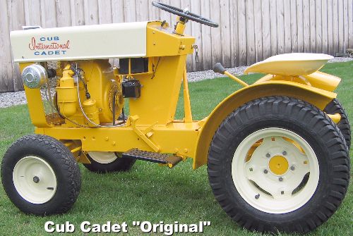 The very first Cub Cadet garden
tractor manufactured is the International Cub Cadet, better known as the
Cub Cadet "Original". The reason this particular tractor
is called the "Original" is because they're the first Cub Cadet garden tractor
that International Harvester made. That's why most folks nowadays call it
the Cub Cadet "Original". IH didn't have a model number because they were
all built basically the same, and they all share the same parts. At the time,
Cub Cadet probably didn't think they were going to build more (and improved)
models in the years following.
The very first Cub Cadet garden
tractor manufactured is the International Cub Cadet, better known as the
Cub Cadet "Original". The reason this particular tractor
is called the "Original" is because they're the first Cub Cadet garden tractor
that International Harvester made. That's why most folks nowadays call it
the Cub Cadet "Original". IH didn't have a model number because they were
all built basically the same, and they all share the same parts. At the time,
Cub Cadet probably didn't think they were going to build more (and improved)
models in the years following.
On these tractors, the power is transferred from a small pulley, that is on the engine, onto a larger pulley that's on the driveshaft by use of a V-belt, which act like a gear reduction. It's approximately a 1.6:1 reduction in driveshaft rotation. This means engine torque is increased approximately 1.6 times the driveshaft because the clutch/driveshaft. This increases the power and torque of the original 6¼hp engine into a 10hp engine (6¼ x 1.6 = 10).
Replacing the Drive Belt in a Cub Cadet "Original" Garden Tractor -
To remove and install the drive belt on an IH Cub Cadet "Original" garden tractor, the entire clutch assembly needs to be removed. After installing the belt and reinstalling the clutch assembly, the belt needs to be tightened by pulling down on the front brace of the clutch assembly (use a pry bar), and tighten the bolts on each side of the frame. This is much easier to do on a platform work table than on the floor or ground.
Convert the V-Belt Drive System to a Chain/Sprocket Drive -
The V-belt on the Cub Cadet "Original" garden tractor can be converted for use with a chain and sprocket drive. This system works great because there'll no belt to slip or rob the engine of horsepower. To make this possible:
Repairing the Drive Clutch -
If the drive clutch holds well, but will not release at times, this means the sliding parts on the driveshaft are dry or the old grease have accumulated dirt and/or have "dried up," causing the parts to bind on the driveshaft.
How to Disassemble and Reassemble the IH Cub Cadet "Original" Garden Tractor Clutch Assembly -
But if the clutch slips, performing the following should cure the problem:
First, resurface the cast iron pressure plates on a large, flat disc or belt sander until they're perfectly flat. (Sanders are not just for woodworking.) If the clutch discs (which is part of the pulley) aren't worn excessively, they can be sanded flat as well to match the flatness of the pressure plates. Just remove the raised places, no more. But if the composite material is worn thin or if you have doubts that it will not grip well, then install new clutch facings on the pulley.
If the clutch composite material
"peels off" or comes loose from the pulley, it can be reattached with a high
strength adhesive, such as
Krazy Glue,
Super Glue,
Gorilla Glue, etc. FYI - When storing an opened container
of Super Glue or liquid threadlock material, store it upright and not laying
flat. The [capped] tip will not dry out and clog when stored upright.
As soon as the composite material is adhered on the pulley, place the
clutch/pulley assembly between two thick flat steel plates to cover the entire
composite material, then place them in a
hydraulic press and apply light pressure to squeeze out
any air bubbles that may get trapped so the composite material will have
a stronger bond and lay flat. If a hydraulic press isn't available, then
using one of the tires that's on a car or truck will place enough pressure,
too. After the glue have dried, lightly sand the composite material on a
large, flat
disc or belt sander to ensure true flatness.
For even better clutch adhesion or "holding power," the OEM pressure spring can be replaced with the aftermarket high pressure red (800± lb.) clutch compression spring. Be sure to drill the 3rd hole to 1/4" and install a heavy coiled/spiral pin, too! Install a new bronze bushing in the clutch release/throw-out bearing if it's worn. Then lubricate the clutch release/throw-out bearing through the factory-installed Zerk grease fitting. Under normal use, the clutch release/throw-out bearing needs to be lubricated once a year for preventive maintenance. Because grease cost a lot less than any mechanical part(s)!
And as far as I'm aware, new composite facings for the IH Cub Cadet "Original"
garden tractor clutch is not available from any source. But 6061 aluminum
can be used as clutch facings on the IH Cub Cadet "Original" garden tractor
clutch pulley. The dimensions of the fabricated aluminum clutch facings are
as follows: 4-1/2" O.D. x 3" I.D. x 1/8" thick.
 Fasten the aluminum to the pulley
with six (for strength) 10-32 UNF x 1/2" length flat head brass screws equally
spaced apart on each side. Offset the threaded holes in the pulley so the
threads of the screws on one side will not interfere with the screws on the
other side. Countersink the heads of the screws into the aluminum with the
heads slightly below the surface of the aluminum. Make sure the aluminum
is perfectly flat before installing it on the pulley, too. And of course,
when using aluminum as clutch material, a stiffer-than-stock pressure spring,
such as the aftermarket
high
pressure red (800± lb.) clutch compression spring, will
be required to prevent clutch slippage.
Fasten the aluminum to the pulley
with six (for strength) 10-32 UNF x 1/2" length flat head brass screws equally
spaced apart on each side. Offset the threaded holes in the pulley so the
threads of the screws on one side will not interfere with the screws on the
other side. Countersink the heads of the screws into the aluminum with the
heads slightly below the surface of the aluminum. Make sure the aluminum
is perfectly flat before installing it on the pulley, too. And of course,
when using aluminum as clutch material, a stiffer-than-stock pressure spring,
such as the aftermarket
high
pressure red (800± lb.) clutch compression spring, will
be required to prevent clutch slippage.
IH Cub Cadet Garden Tractor Mechanical PTO Clutch Replacement Parts, Kits and Rebuild Service - Click here to contact A-1 Miller's Performance Enterprises to place an order, send your parts for repairing, and/or for FREE professional and honest technical customer service assistance and support and payment options. Please contact A-1 Miller's if you need a part or parts, or service(s) performed that's not listed or mentioned in this website. | [Top of Page]
 Mule Drive V-Belt
Idler Pulley. Fits Cub Cadet garden tractor models 70, 71, 72, 73, 86, 100,
102, 104, 105, 106, 107, 108, 109, 122, 123, 124, 125, 126, 127, 128, 129,
147, 149, 169, 800, 1000, 1100, 1200, 1250, 1450 and 1650. Mule Drive V-Belt
Idler Pulley. Fits Cub Cadet garden tractor models 70, 71, 72, 73, 86, 100,
102, 104, 105, 106, 107, 108, 109, 122, 123, 124, 125, 126, 127, 128, 129,
147, 149, 169, 800, 1000, 1100, 1200, 1250, 1450 and 1650.
|
|
 Carbon Wear Button for IH
Cub Cadet Garden Tractor Mechanical PTO Clutch. Fits Cub Cadet garden tractor
models 70, 71, 72, 73, 86, 100, 102, 104, 105, 106, 107, 108, 109, 122, 123,
124, 125, 126, 127, 128, 129, 147, 149 and 169. This part installs in
the mower deck engagement lever on the frame of tractor. Makes contact with
the metal button to the right. Secure with high strength glue. OEM Cub
Cadet part #'s IH-473483-R1 and IH-473483-R2. 11.60 each, plus shipping
& handling. Carbon Wear Button for IH
Cub Cadet Garden Tractor Mechanical PTO Clutch. Fits Cub Cadet garden tractor
models 70, 71, 72, 73, 86, 100, 102, 104, 105, 106, 107, 108, 109, 122, 123,
124, 125, 126, 127, 128, 129, 147, 149 and 169. This part installs in
the mower deck engagement lever on the frame of tractor. Makes contact with
the metal button to the right. Secure with high strength glue. OEM Cub
Cadet part #'s IH-473483-R1 and IH-473483-R2. 11.60 each, plus shipping
& handling. |
 Metal Thrust Button for
IH Cub Cadet Garden Tractor Mechanical PTO Clutch. Fits Cub Cadet garden
tractor models 70, 71, 72, 73, 86, 100, 102, 104, 105, 106, 107, 108, 109,
122, 123, 124, 125, 126, 127, 128, 129, 147, 149 and 169. This part installs
in the center of the PTO clutch assembly. Makes contact with the carbon button
to the left. OEM Cub Cadet part # IH-473477-R3. $16.70 each, plus
shipping & handling. Metal Thrust Button for
IH Cub Cadet Garden Tractor Mechanical PTO Clutch. Fits Cub Cadet garden
tractor models 70, 71, 72, 73, 86, 100, 102, 104, 105, 106, 107, 108, 109,
122, 123, 124, 125, 126, 127, 128, 129, 147, 149 and 169. This part installs
in the center of the PTO clutch assembly. Makes contact with the carbon button
to the left. OEM Cub Cadet part # IH-473477-R3. $16.70 each, plus
shipping & handling. |
 Mechanical PTO
Clutch Rebuild Kit. Designed for and fits all narrow frame Cub Cadet models
70, 71, 73, 100, 102, 104, 105, 106, 107, 122, 123, 124, 125, 126, 127 and
147. (Unlike the tractors listed below, the model of tractors listed here
have a smaller mower deck, which require less pressure for the PTO clutch.)
OEM Cub Cadet part #'s 759-3490, IH-483525-R92. $135.25 each, plus
shipping & handling. Mechanical PTO
Clutch Rebuild Kit. Designed for and fits all narrow frame Cub Cadet models
70, 71, 73, 100, 102, 104, 105, 106, 107, 122, 123, 124, 125, 126, 127 and
147. (Unlike the tractors listed below, the model of tractors listed here
have a smaller mower deck, which require less pressure for the PTO clutch.)
OEM Cub Cadet part #'s 759-3490, IH-483525-R92. $135.25 each, plus
shipping & handling.
A-1 Miller's Professional Rebuild Service - Rebuild YOUR IH Cub Cadet mechanical PTO clutch assembly. $75.00 labor each, parts are extra charge, plus return shipping & handling.
A-1 Miller's Professional Rebuild Service - Rebuild YOUR IH Cub Cadet mechanical PTO clutch assembly. $75.00 labor each, parts are extra charge, plus return shipping & handling.
IH Cub Cadet Mechanical PTO Clutch Assembly. Fully machined with new replacement parts. Double pressure springs. Designed for and fits solid-mounted engine wide frame IH Cub Cadet models 86, 108, 109, 128, 129, 149 and 169. NOTE: Unlike the PTO clutch assembly listed above with the single pressure spring, to prevent clutch slippage when engaged, this particular clutch has two pressure springs for a larger size mower deck. Comes with one year workmanship warranty. OEM Cub Cadet part #'s 75903489 and IH-548352-R92. $350.00 each, plus shipping & handling. (When available or in stock.) A-1 Miller's Professional Rebuild Service - Rebuild YOUR IH Cub Cadet mechanical PTO clutch assembly. Comes with one year workmanship warranty. $75.00 labor each, replacement parts are extra charge, plus return shipping & handling.
|
|
How to Remove the IH Cub Cadet PTO Clutch/Pulley Assembly on IH Cub Cadet garden tractor models 70, 71, 72, 73, 86, 100, 102, 104, 105, 106, 107, 108, 109, 122, 123, 124, 125, 126, 127, 128, 129, 149 and 169 - [Top of Page]


 Remove the Allen head set screws from the clutch/pulley assembly.
There's a total of 6 set screws, a short one on top of a longer one in each
hole of the clutch/pulley assembly. (The short set screws prevent the longer
ones from loosening.) Anyway, the long ones must be removed before the
pulley/clutch assembly can come off the ball bearing.
Remove the Allen head set screws from the clutch/pulley assembly.
There's a total of 6 set screws, a short one on top of a longer one in each
hole of the clutch/pulley assembly. (The short set screws prevent the longer
ones from loosening.) Anyway, the long ones must be removed before the
pulley/clutch assembly can come off the ball bearing.
How to Remove the Mechanical IH Cub Cadet Garden Tractor PTO Basket/Pulley from the Crankshaft - [Top of Page]
How to Use A-1 Miller's Mechanical IH Cub Cadet Garden Tractor PTO Basket/Pulley Removal Tool - [Top of Page]
This is a fool-proof method to easily and safely remove the basket/pulley from the crankshaft without bending or damaging it. Use this removal tool with a 2-jaw gear puller (The PROTO 4021 2-jaw gear puller [shown to the right] works great for many tough jobs) and heavy duty 1/2" impact wrench. This versatile removal tool can also be used to remove stubborn steel pulleys and sprockets from other makes and models of garden tractor engines, transmissions, transaxles, right angle gearboxes, jackshafts, etc.

 Fabricate a
basket/pulley removal tool from 1-3/4" I.D. x 2-1/4" O.D. x 2" length heavy
gauge (1/4" wall thickness) steel tubing. Drill one 11/32" hole at each end
of the tool (this is so the tool can be used in either direction), and
cut/grind/machine two slots 180º midway on each side of the tool for
the jaws of a 2-jaw gear puller tool.
Fabricate a
basket/pulley removal tool from 1-3/4" I.D. x 2-1/4" O.D. x 2" length heavy
gauge (1/4" wall thickness) steel tubing. Drill one 11/32" hole at each end
of the tool (this is so the tool can be used in either direction), and
cut/grind/machine two slots 180º midway on each side of the tool for
the jaws of a 2-jaw gear puller tool.
How to Prevent the IH Cub Cadet Garden Tractor PTO basket/pulley from Loosening on the Crankshaft - [Top of Page]
Tools and Parts Required Are:
 Two 5/16-18 UNC x 1/2" length Allen set screws.
Instructions:
 Remove
the OEM set screws from the hub in the pulley, and remove the pulley from
the crankshaft. (If necessary, use A-1 Miller's PTO Puller Puller Tool
as instructed above to avoid damage to the pulley.)
Remove
the OEM set screws from the hub in the pulley, and remove the pulley from
the crankshaft. (If necessary, use A-1 Miller's PTO Puller Puller Tool
as instructed above to avoid damage to the pulley.)
 To place an order, send your item(s) for repairing, and/or
for customer service assistance, and FREE honest and accurate technical support,
please contact: A-1 Miller's Performance Enterprises, 12091 N Route B,
Hallsville, MO (Missouri) 65255-9604 USA. Please call in your order or send
an email with a list parts you need and your contact information.
To place an order, send your item(s) for repairing, and/or
for customer service assistance, and FREE honest and accurate technical support,
please contact: A-1 Miller's Performance Enterprises, 12091 N Route B,
Hallsville, MO (Missouri) 65255-9604 USA. Please call in your order or send
an email with a list parts you need and your contact information.
 Phone: 1-573-881-7229 (cell;
call, text or leave voicemail). Please call Monday-Friday, 9am to 5pm, Central
time zone, except holidays. If no answer, please try again later.
Phone: 1-573-881-7229 (cell;
call, text or leave voicemail). Please call Monday-Friday, 9am to 5pm, Central
time zone, except holidays. If no answer, please try again later.
 E-mail:
pullingtractor@aol.com. A-1 Miller's
shop is open to the public Monday-Friday, 9am to 5pm, Central time zone,
with an appointment on weekends, except holidays. If you're the kind of person
who don't trust delivery/shipping companies (mis)handling your high-dollar
and fragile merchandise, you can make the long drive to A-1 Miller's new
shop (click image to the right) to personally purchase parts, or drop off
and/or pick up your carburetor, clutch assembly, and/or other parts for repairing
and/or rebuilding. Or visit our new shop to drop off your parts. Please contact
us before coming so we'll be at our shop waiting for your arrival. When you
visit our shop, you will be dealing directly with the owner for the best
customer service. "The road to a [trusted] friend's house (or shop) is
never long." Don't sacrifice quality workmanship for distance.
Payment Options below.
Photos
of our new building/shop are posted here!
12091 N Route B, Hallsville, MO - Google Maps.
[Return To Previous Paragraph, Section
or Website]
E-mail:
pullingtractor@aol.com. A-1 Miller's
shop is open to the public Monday-Friday, 9am to 5pm, Central time zone,
with an appointment on weekends, except holidays. If you're the kind of person
who don't trust delivery/shipping companies (mis)handling your high-dollar
and fragile merchandise, you can make the long drive to A-1 Miller's new
shop (click image to the right) to personally purchase parts, or drop off
and/or pick up your carburetor, clutch assembly, and/or other parts for repairing
and/or rebuilding. Or visit our new shop to drop off your parts. Please contact
us before coming so we'll be at our shop waiting for your arrival. When you
visit our shop, you will be dealing directly with the owner for the best
customer service. "The road to a [trusted] friend's house (or shop) is
never long." Don't sacrifice quality workmanship for distance.
Payment Options below.
Photos
of our new building/shop are posted here!
12091 N Route B, Hallsville, MO - Google Maps.
[Return To Previous Paragraph, Section
or Website]
Payment Options, and We Ship to Canada and
Worldwide 
Item(s) in a package or cushioned envelope weighing less than 1 lb. is sent
by US Postal Service Airmail Letter Post for a 4-7 days delivery. Packaged
item(s) weighing over 1 lb. and up to 66 lb. is sent by US Postal Service
Airmail Parcel Post for a 4-10 days delivery. I cannot use the US Postal
Services' Flat Rate Priority Mail envelopes and boxes to ship outside U.S.
territories. Item(s) weighing over 67 lbs. or more is sent by FedEx Ground
or equivalent services. We try to keep our shipping cost to customers within
reason. Therefore, we don't ship our products in a fancy-looking package
with our company name and/or logo on it because most customers will just
toss it in the trash after they remove the contents. And being there is no
USPS tracking number outside the US, all I can do is make sure I write your
address correctly on the customs form and on your package.
My websites are not set up to process orders and accept payments. Therefore, to place an order with me, please call either number above or send an email with a list of parts you need, with your name, complete and correct postal mailing address and phone number. For payment options, I accept cash (in person), USPS Postal Money Orders, cashier's checks, business checks, MasterCard, VISA, Discover, American Express (please add 2.5% to the total amount for the credit/debit card processor's surcharge). If paying with a credit/debit card, please call me at either number above. Or to make a payment to me through PayPal, please click this link: https://www.paypal.com. Or use Cash App (username: pullingtractor) or Venmo (username: Pullingtractor) to make a payment to me. And be sure to mention a description of what the payment is for with your full name, postal address, phone number and email address. If sending a money order or cashier's check, please include a note in the envelope with your name, complete mailing address, phone number, email address and a description of what the payment is for. I'll make a note of your order when I have all your information, and I may have to order some of the parts on your list, which should take a few days to come in, but I will send everything to you as soon as I have the parts in stock after I receive your payment.


Return To Previous Website | Top of Page | Copyright © 1996-Present. This website created, designed and maintained by A-1 Miller's Performance Enterprises
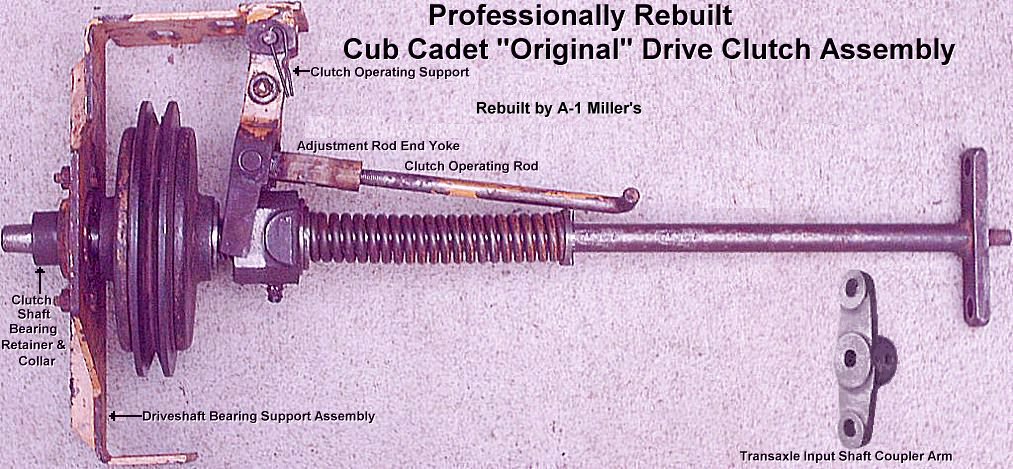
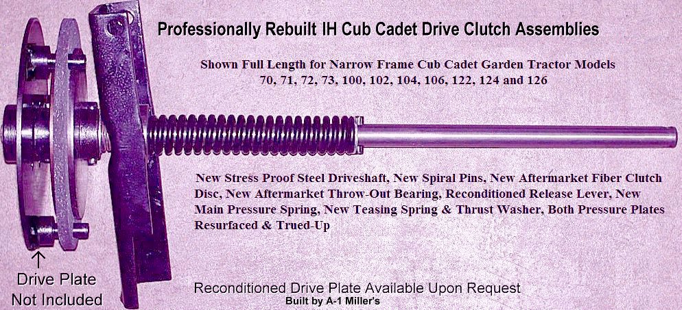
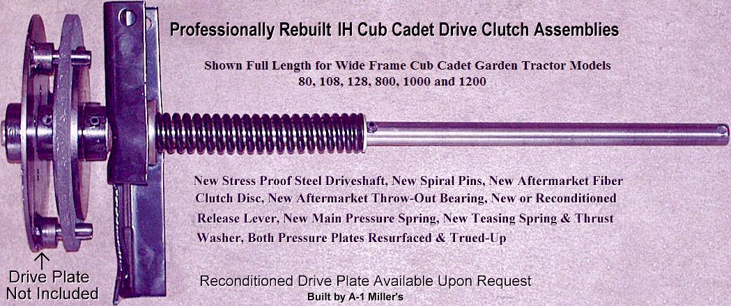
 Driveshafts for IH- and MTD-built
Cub Cadet Clutch Drive Garden Tractor models 70, 71, 72, 73, 86, 100, 102,
104, 106, 108, 122, 124, 126, 128, 580, 582, 800, 1000, 1050, 1200, 1282
(clutch drive model), 1604, 1606 and 1806, including models 1250, 1450 and
1650 with a hydrostatic disconnect attachment. NOTE:
These driveshafts are made to order. When ordering, please specify model
of Cub Cadet garden tractor and possibly exact length and exactly where the
coiled/spiral pin holes needs to be drilled. Please indicate if you want
the 3rd hole drilled for the main pressure spring or if you are going to
use a
Driveshafts for IH- and MTD-built
Cub Cadet Clutch Drive Garden Tractor models 70, 71, 72, 73, 86, 100, 102,
104, 106, 108, 122, 124, 126, 128, 580, 582, 800, 1000, 1050, 1200, 1282
(clutch drive model), 1604, 1606 and 1806, including models 1250, 1450 and
1650 with a hydrostatic disconnect attachment. NOTE:
These driveshafts are made to order. When ordering, please specify model
of Cub Cadet garden tractor and possibly exact length and exactly where the
coiled/spiral pin holes needs to be drilled. Please indicate if you want
the 3rd hole drilled for the main pressure spring or if you are going to
use a  Driveshafts for IH Cub Cadet
Hydrostatic Drive Garden Tractor models 105, 107, 109, 123, 125, 127, 129,
147, 109, 129, 149 and 169. NOTE: These driveshafts, with the OEM factory
designed machined-down 3/8" diameter support end, are originally used with
Cub Cadet coupler arm with the 25/64" center hole (
Driveshafts for IH Cub Cadet
Hydrostatic Drive Garden Tractor models 105, 107, 109, 123, 125, 127, 129,
147, 109, 129, 149 and 169. NOTE: These driveshafts, with the OEM factory
designed machined-down 3/8" diameter support end, are originally used with
Cub Cadet coupler arm with the 25/64" center hole ( Driveshafts for Cub Cadet
Garden Tractor models 482, 580, 582 Special, 1100, 1204, 1604, 1606 and
1806. (Belt drive models; engine to
Driveshafts for Cub Cadet
Garden Tractor models 482, 580, 582 Special, 1100, 1204, 1604, 1606 and
1806. (Belt drive models; engine to  Driveshafts for MTD-built
Cub Cadet Hydrostatic Drive Garden Tractor models 680, 682, 782, 782D, 784,
882, 982, 1210, 1211, 1282, 1512, 1541, 1710, 1711, 1712, 1810, 1811, 1812
and 1860.
Driveshafts for MTD-built
Cub Cadet Hydrostatic Drive Garden Tractor models 680, 682, 782, 782D, 784,
882, 982, 1210, 1211, 1282, 1512, 1541, 1710, 1711, 1712, 1810, 1811, 1812
and 1860.
 Driveshafts for MTD-built
Cub Cadet Hydrostatic Drive Garden Tractor models 1872 and 2072. Available
only in stress proof steel.
Driveshafts for MTD-built
Cub Cadet Hydrostatic Drive Garden Tractor models 1872 and 2072. Available
only in stress proof steel.
 3/16" diameter x 3/4" length.
Fits IH Cub Cadet "Original" garden tractor driveshaft splined direct drive
coupling and fits shift yoke in IH Cub Cadet creeper drive. 3,100 P.S.I.
breaking strength.
3/16" diameter x 3/4" length.
Fits IH Cub Cadet "Original" garden tractor driveshaft splined direct drive
coupling and fits shift yoke in IH Cub Cadet creeper drive. 3,100 P.S.I.
breaking strength.
 3/16" diameter x 1" length.
Fits behind main pressure spring in Cub Cadet Original driveshaft (OEM 3/32"
hole must be drilled out [enlarged] to 3/16") and fits splined carrier in
IH Cub Cadet creeper drive.
3/16" diameter x 1" length.
Fits behind main pressure spring in Cub Cadet Original driveshaft (OEM 3/32"
hole must be drilled out [enlarged] to 3/16") and fits splined carrier in
IH Cub Cadet creeper drive.
 1/4" diameter x 1" length. Fits
behind main pressure spring and for small O.D. tubular coupler or coupler
arm. Replaces discontinued Cub Cadet part # 915-3014. $1.50 each,
plus shipping & handling.
1/4" diameter x 1" length. Fits
behind main pressure spring and for small O.D. tubular coupler or coupler
arm. Replaces discontinued Cub Cadet part # 915-3014. $1.50 each,
plus shipping & handling.
 1/4" diameter x 1-1/2" length.
Fits both pressure plates and large O.D. tubular coupler.
1/4" diameter x 1-1/2" length.
Fits both pressure plates and large O.D. tubular coupler.
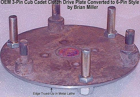
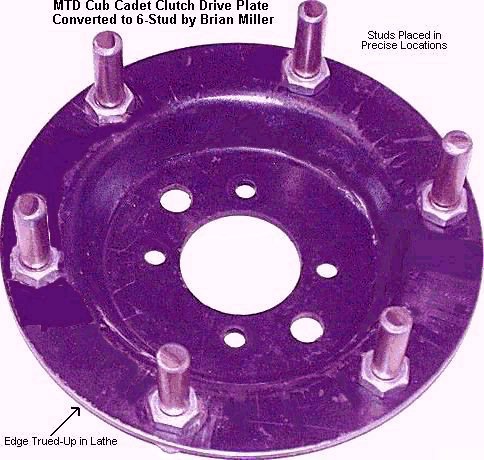


 Reinforced Rubber Driveshaft
Flex Coupler Disc. Designed specifically for IH Cub Cadet "Original"
garden tractor, and Cub Cadet hydrostatic drive garden tractor models 105,
107, 109, 123, 125, 127, 129, 147, 149 and 169. Cannot be used on the Cub
Cadet "Quiet Line" garden tractor models due to the small center hole. Very
tough, reinforced rubber/weaved composite material. Allows for out-of-alignment
rotation of driveshaft to prevent damage to hydrostatic pump. Can also be
used in a steering shaft setup of a custom-built mini-rod pulling tractor
as a type of U-joint with a maximum 35º rotational angle with coupler
arm(s) listed above. 13/32" bolt holes spaced 3" apart. OEM Cub Cadet part
# IH-376257-R3. $41.20 each, plus shipping & handling.
Reinforced Rubber Driveshaft
Flex Coupler Disc. Designed specifically for IH Cub Cadet "Original"
garden tractor, and Cub Cadet hydrostatic drive garden tractor models 105,
107, 109, 123, 125, 127, 129, 147, 149 and 169. Cannot be used on the Cub
Cadet "Quiet Line" garden tractor models due to the small center hole. Very
tough, reinforced rubber/weaved composite material. Allows for out-of-alignment
rotation of driveshaft to prevent damage to hydrostatic pump. Can also be
used in a steering shaft setup of a custom-built mini-rod pulling tractor
as a type of U-joint with a maximum 35º rotational angle with coupler
arm(s) listed above. 13/32" bolt holes spaced 3" apart. OEM Cub Cadet part
# IH-376257-R3. $41.20 each, plus shipping & handling.

 Professionally Machine
YOUR OEM Cub Cadet garden tractor drive clutch pressure plates. Service
Include: Resurface both clutch contact areas in my metal lathe until perfectly
flat with a slick, smooth surface so a new clutch friction disc will adhere
100% to prevent slippage; true-up outer edge in my metal lathe to prevent
wobble and out-of-balance rotation (which will cause the pilot bushing to
wear); and grind out worn slot(s) in rear hub until straight so clutch disc
will disengage every time when pedal is depressed. $40.00 labor for
two pressure plates, plus return shipping & handling.
Professionally Machine
YOUR OEM Cub Cadet garden tractor drive clutch pressure plates. Service
Include: Resurface both clutch contact areas in my metal lathe until perfectly
flat with a slick, smooth surface so a new clutch friction disc will adhere
100% to prevent slippage; true-up outer edge in my metal lathe to prevent
wobble and out-of-balance rotation (which will cause the pilot bushing to
wear); and grind out worn slot(s) in rear hub until straight so clutch disc
will disengage every time when pedal is depressed. $40.00 labor for
two pressure plates, plus return shipping & handling.

 Clutch Adjustment/Release Rod.
Fits Cub Cadet garden tractor models 70, 71, 72, 73, 100, 102, 104, 106,
122, 124 and 126. Replace severely worn or missing adjustment/release rod.
Clutch Adjustment/Release Rod.
Fits Cub Cadet garden tractor models 70, 71, 72, 73, 100, 102, 104, 106,
122, 124 and 126. Replace severely worn or missing adjustment/release rod.
 Clutch Adjustment/Release Rod.
Fits Cub Cadet garden tractor models 86, 108, 128, and models 800, 1000 and
1200 with axle/caliper brakes. Replace severely worn or missing
adjustment/release rod.
Clutch Adjustment/Release Rod.
Fits Cub Cadet garden tractor models 86, 108, 128, and models 800, 1000 and
1200 with axle/caliper brakes. Replace severely worn or missing
adjustment/release rod.
 Clutch Adjustment/Release Rod.
Fits Cub Cadet garden tractor models 580, 582, 1050, 1282 (clutch drive model),
1535, 1604, 1606 and 1806. Replace severely worn or missing adjustment/release
rod.
Clutch Adjustment/Release Rod.
Fits Cub Cadet garden tractor models 580, 582, 1050, 1282 (clutch drive model),
1535, 1604, 1606 and 1806. Replace severely worn or missing adjustment/release
rod.
 Steel Spacer/Cup for Teasing
Spring. Designed only for Cub Cadet garden tractor model 1050.
IMPORTANT: Apply grease on driveshaft before installing spacer
and cup for easier clutch disengagement.
Steel Spacer/Cup for Teasing
Spring. Designed only for Cub Cadet garden tractor model 1050.
IMPORTANT: Apply grease on driveshaft before installing spacer
and cup for easier clutch disengagement.
 Clutch Release/Throw-Out Bearing.
Fits and designed for IH Cub Cadet wide frame/solid mounted engine garden
tractor models 86, 108 and 128. Precision, high-speed sealed collar bearing
w/short pressed-in steel sleeve. This larger diameter bearing covers more
area in the wide frame
Clutch Release/Throw-Out Bearing.
Fits and designed for IH Cub Cadet wide frame/solid mounted engine garden
tractor models 86, 108 and 128. Precision, high-speed sealed collar bearing
w/short pressed-in steel sleeve. This larger diameter bearing covers more
area in the wide frame 
 Clutch Release/Throw-Out Bearings
with or without Bushing/Sleeve. Fits and designed for certain Cub Cadet "Quiet
Line" ISO-mounted engine garden tractor models 800, 1000, 1200, including
Cub Cadet models 1250, 1450 and 1650 with hydrostatic disconnect attachment.
Also fits Cub Cadet models 580, 582, 1050, 1282 (later model), 1535, 1604,
1606 and 1806. Bearing dimensions: .780" I.D. x 1.850" O.D. x .550" height.
This larger diameter bearing covers more area in the wide and spread frame
Clutch Release/Throw-Out Bearings
with or without Bushing/Sleeve. Fits and designed for certain Cub Cadet "Quiet
Line" ISO-mounted engine garden tractor models 800, 1000, 1200, including
Cub Cadet models 1250, 1450 and 1650 with hydrostatic disconnect attachment.
Also fits Cub Cadet models 580, 582, 1050, 1282 (later model), 1535, 1604,
1606 and 1806. Bearing dimensions: .780" I.D. x 1.850" O.D. x .550" height.
This larger diameter bearing covers more area in the wide and spread frame
 800± lb. "Red" Spring.
$35.00 each, plus shipping & handling. (± means more or
less PSI depending on compressed length of spring when installed on
driveshaft.)
800± lb. "Red" Spring.
$35.00 each, plus shipping & handling. (± means more or
less PSI depending on compressed length of spring when installed on
driveshaft.)
 Spherical, Swivel, Self-Aligning
5/8" I.D. Set Screw Collar Sealed Ball Bearing with two-bolt, two-piece stamped
steel retainers. Retainers has 2-1/2" bolt hole spacing. Alternative to using
bearing assembly above. High quality aftermarket. Replaces discontinued Cub
Cadet part #'s IH-468390-R93 (collar bearing), IH-468391-R11 (eccentric locking
collar) and IH-376272-R1 (retainers). $25.00 each, plus shipping &
handling.
Spherical, Swivel, Self-Aligning
5/8" I.D. Set Screw Collar Sealed Ball Bearing with two-bolt, two-piece stamped
steel retainers. Retainers has 2-1/2" bolt hole spacing. Alternative to using
bearing assembly above. High quality aftermarket. Replaces discontinued Cub
Cadet part #'s IH-468390-R93 (collar bearing), IH-468391-R11 (eccentric locking
collar) and IH-376272-R1 (retainers). $25.00 each, plus shipping &
handling.

 Mechanical PTO Clutch Rebuild
Kit. Designed for and fits wide frame Cub Cadet models 86, 108, 109, 128,
129, 149 and 169. (Unlike the tractors listed above, the model of tractors
listed here have a larger mower deck, which require more pressure for the
PTO clutch to prevent it from slipping and possibly burning up.) OEM Cub
Cadet part #'s 759-3489, IH-548352-R92. $139.90 each, plus shipping
& handling.
Mechanical PTO Clutch Rebuild
Kit. Designed for and fits wide frame Cub Cadet models 86, 108, 109, 128,
129, 149 and 169. (Unlike the tractors listed above, the model of tractors
listed here have a larger mower deck, which require more pressure for the
PTO clutch to prevent it from slipping and possibly burning up.) OEM Cub
Cadet part #'s 759-3489, IH-548352-R92. $139.90 each, plus shipping
& handling.
 1" I.D.
Collar Bearing with Eccentric Locking Collar. Fits IH Cub Cadet mechanical
PTO clutch assembly listed above, and IH Cub Cadet garden tractor models
70, 71, 72, 73, 86, 100, 102, 104, 105, 106, 107, 108, 109, 122, 123, 124,
125, 126, 127, 128, 129, 147, 149 and 169. NOTE: If the PTO clutch/pulley
assembly is already removed, and if the ball bearing and locking are difficult
to remove, use a large 2-jaw gear puller (The
1" I.D.
Collar Bearing with Eccentric Locking Collar. Fits IH Cub Cadet mechanical
PTO clutch assembly listed above, and IH Cub Cadet garden tractor models
70, 71, 72, 73, 86, 100, 102, 104, 105, 106, 107, 108, 109, 122, 123, 124,
125, 126, 127, 128, 129, 147, 149 and 169. NOTE: If the PTO clutch/pulley
assembly is already removed, and if the ball bearing and locking are difficult
to remove, use a large 2-jaw gear puller (The