
 Electrical Solutions for Various
Older Small Engines and Competition Garden Pulling Tractors
Electrical Solutions for Various
Older Small Engines and Competition Garden Pulling Tractors
Electrical Solutions for Various
Older Small Engines and Competition Garden Pulling Tractors
Electrical Solutions for Various
Older Small Engines and Competition Garden Pulling Tractors
Educating and Inspiring Small Engine, Lawn & Garden, and Garden
Pulling Tractor Enthusiasts Since 1996. Where Science and Common Sense Come
Together for Safety and Improved Engine/Tractor Performance |
A-1
Miller's Performance Enterprises - Parts & Services
Webstore |  Overstocked Kohler Engine Parts & Cub Cadet Garden Tractor
Parts | Available Soon - Detailed
Illustrated Plans on How to Construct Professional Pulling Sleds
Overstocked Kohler Engine Parts & Cub Cadet Garden Tractor
Parts | Available Soon - Detailed
Illustrated Plans on How to Construct Professional Pulling Sleds
This website was updated 7/25/26. Nowadays,
prices are subject to change without notice. Click
Refresh to see any
changes or updates. Optimized for 1152 x 864 computer screen resolution.
To search for a word or phrase in any of my websites, press the CTRL
 and F
and F  keys on
your keyboard simultaneously to open the Find or Search dialog box in your
web browser. And being I have no
apprentice to update and pay for my websites so they'll
continue to be on the Internet, they will be removed forever when I'm no
longer around. Scroll down this website or click/tap the links below to
jump down to...
keys on
your keyboard simultaneously to open the Find or Search dialog box in your
web browser. And being I have no
apprentice to update and pay for my websites so they'll
continue to be on the Internet, they will be removed forever when I'm no
longer around. Scroll down this website or click/tap the links below to
jump down to...
Be Professional With Your Tractor's or Equipment's Wiring!
First of all, an engine's ignition system is completely separate from its electrical charging system. One has absolutely nothing to do with the other. The power for a battery-powered ignition system comes from the battery while cranking the engine to start it. Once it starts, the charging system takes over, and while the engine is running at full governed speed, the charging system recharges the battery, powers all electrical accessories, and powers the battery-powered ignition system. A self-energizing magneto or electronic/solid state ignition system do not depend on power from the battery or charging system whatsoever.


 When connecting the wires for an electrical system, don't just
make a connection by twisting bare wires together by hand and taping them
up. All this does is allow moisture between the wires and in time, lets corrosion
set in, causing a faulty connection. An older, experienced electrical engineer
once said: "Sometimes electrical problems are mechanical." Meaning a loose
or poor connection, or a faulty switch. Therefore, it's better to solder
the wires together, then tape them up with electrical tape or use appropriate
size
heat shrinkable tubing. Or for a "clean" and professional
look, use "crimp" style wire connectors to connect two wires together, or
connect a wire to a coil stud terminal or switch terminal. Use a
wire stripper / crimp connector tool to secure the crimp
connectors to the wire. Use a bench vise to crimp heavy connectors to battery
cables. Route the wiring along the inside of the frame in a safe and secure
manner, away from the spinning flywheel and clutch/driveshaft, moving levers,
and hot exhaust areas.
When connecting the wires for an electrical system, don't just
make a connection by twisting bare wires together by hand and taping them
up. All this does is allow moisture between the wires and in time, lets corrosion
set in, causing a faulty connection. An older, experienced electrical engineer
once said: "Sometimes electrical problems are mechanical." Meaning a loose
or poor connection, or a faulty switch. Therefore, it's better to solder
the wires together, then tape them up with electrical tape or use appropriate
size
heat shrinkable tubing. Or for a "clean" and professional
look, use "crimp" style wire connectors to connect two wires together, or
connect a wire to a coil stud terminal or switch terminal. Use a
wire stripper / crimp connector tool to secure the crimp
connectors to the wire. Use a bench vise to crimp heavy connectors to battery
cables. Route the wiring along the inside of the frame in a safe and secure
manner, away from the spinning flywheel and clutch/driveshaft, moving levers,
and hot exhaust areas.
When removing and installing the engine in and out of a competition garden pulling tractor (or any vehicle as far as this subject is concerned), for whatever reason, install male and female bullet or spade quick disconnect electrical connectors (or any type of quick disconnect electrical connectors as long as they're insulated from the engine and tractor/vehicle frame) in the wiring circuit that's connected to the points, ignition module, coil, charging system, or anything else that's wired to the engine, except for the heavy battery cable that connects to the starter motor. The use of quick disconnect electrical connectors allows for much easier and quicker disconnection of the wires. Example: Before removing engine, the points cover will need to be removed, then the wire needs to be disconnected from the points terminal screw; and then remove the nuts from the ignition coil and then take a chance on losing one of the small nuts. No tools are required for use with quick disconnect electrical connectors either. No need to unscrew this, unbolt that, just unplug the connectors by hand to remove the engine, and plug them back together after reinstalling the engine. It's that simple. Many professional race cars, funny cars, dragsters and NASCAR use this method to speed up the quick engine rebuild or swap process in the pit area at the track on race day. And most electronic appliances, such as computers, TVs, etc., used this method for many years to simplify removing and installing circuit boards and various components. Makes life a lot easier.

Always install either an in-line round- or blade-type fuse holder, panel-mount fuse holder, blade-type automatic reset circuit breaker, or a stud-type automatic reset circuit breaker in the primary wire that's connected directly to the battery positive (+) post. (The small wire that provides power to all electrical components.) An important thing to remember is if using a universal automatic reset circuit breaker in a competition garden pulling tractor, don't fasten it to any part of the tractor! Instead, allow it to dangle free by the wires (hide it inside the steering pedestal assembly), and wrap electrical tape around it so the terminals won't short out against any bare metal part of the tractor. The reason the circuit breaker shouldn't be mounted solid to any part of the tractor is because at high RPM or wide open throttle, normal engine vibration, that's transferred throughout the entire tractor, will cause the bimetallic strip (contact spring or "flapper") inside the circuit breaker to vibrate (a lot) and become momentarily and erratically disconnected, causing the engine to misfire badly and misfire or "cut out" while going down the track. Having a fuse or circuit breaker installed (and amp gauge or volt meter; if the engine has a charging system) is very important to prevent failure of electrical components. Because by the time you smell something burning or see smoke, it may be too late.

 Install an
amp gauge or
volt meter to monitor exactly what the charging system
on your engine is doing. Having an amp gauge or volt meter installed is very
important in monitoring the charging system to prevent premature failure
of electrical components. As battery becomes fully charged, needle slowly
moves from positive side (+) to zero (0). Needle will stay on negative side
(–) if no charge goes to the battery. Or gauge will not show any charge
at all if charging system is not working. With a working amp gauge or volt
meter, if the charging system continues to charge on the plus (+) side with
no gradual moving back of the needle to zero while the engine is running
at full governed speed, due to a faulty voltage rectifier/regulator, this
will send too much voltage to or overcharge the battery, which could eventually
burn up the cells in the battery, or burn up the primary windings in a [battery]
ignition coil, burn up an electric PTO clutch, burn out light bulbs, the
[battery powered] electronic ignition control module
(crank-trigger and flywheel-trigger), and
other electrical accessories.
Install an
amp gauge or
volt meter to monitor exactly what the charging system
on your engine is doing. Having an amp gauge or volt meter installed is very
important in monitoring the charging system to prevent premature failure
of electrical components. As battery becomes fully charged, needle slowly
moves from positive side (+) to zero (0). Needle will stay on negative side
(–) if no charge goes to the battery. Or gauge will not show any charge
at all if charging system is not working. With a working amp gauge or volt
meter, if the charging system continues to charge on the plus (+) side with
no gradual moving back of the needle to zero while the engine is running
at full governed speed, due to a faulty voltage rectifier/regulator, this
will send too much voltage to or overcharge the battery, which could eventually
burn up the cells in the battery, or burn up the primary windings in a [battery]
ignition coil, burn up an electric PTO clutch, burn out light bulbs, the
[battery powered] electronic ignition control module
(crank-trigger and flywheel-trigger), and
other electrical accessories.
To determine the size of fuse or circuit breaker, figure how many amps all the connected electrical accessories draw, then use a fuse or circuit breaker with an amp rating slightly higher to prevent the fuse from burning out or the circuit breaker from overloading and popping. If a short occurs, the fuse will need to be replaced and the circuit breaker will automatically reset itself.
 Also, it's a good idea to install
a main disconnect/cutoff switch to kill electric
power to everything on the equipment. This is useful when equipment is not
used for a period of time to prevent a slow drain on the battery, prevent
short circuits when performing electrical service on equipment, or for a
pulling tractor to prevent accidental starts or to prevent sabotage at the
pull sites from disgruntled pullers.
Also, it's a good idea to install
a main disconnect/cutoff switch to kill electric
power to everything on the equipment. This is useful when equipment is not
used for a period of time to prevent a slow drain on the battery, prevent
short circuits when performing electrical service on equipment, or for a
pulling tractor to prevent accidental starts or to prevent sabotage at the
pull sites from disgruntled pullers.
How Lead-Acid Batteries Go Bad - (Added 2/6/21) Top of Page
In a lead-acid automotive battery, as the battery ages, the lead (the soft, heavy, toxic, malleable metallic element) on the plates of one cell falls off and builds up on the bottom of the battery (this always happen with a cell on the positive (+) post), it will short-out that cell, causing a dead cell. There is no fix for this whatsoever. The only solution is to replace it with a new battery and keep it fully charged. Or when a battery sits too long with no charge, the activity of the acid will become neutralized and become water-like. If you're lucky, the battery MIGHT be able to be reactivated with a trickle charger. A trickle charger provides low amperage and will slowly reactivate the chemical reaction of the acid/water to the cells. Otherwise, if it won;t recharge, then the battery is bad and needs to be replaced with a new one. Or, the acid/water can be drained and replaced with fresh acid/water, and "maybe" the battery can be fully charged at a low rate for activation again. Or, if the charging system on the engine continually charge the battery at full amperage due to a faulty voltage regulator or voltage rectifier/regulator, this will "burn up" the acid/water and the lead plates, causing a bad battery. The only solution for this is install a new voltage regulator or voltage rectifier/regulator and replace the battery with a new one. Does battery acid contain water? Is it okay to add water or acid to a lead acid battery? Is it okay to add water to a lead acid battery?
Whenever I take an automotive battery that's still under warranty, but I know for a fact it's bad, back to the store to have it replaced, and the store test it and says it's still in good condition (when you know for a fact it's definitely not; good starter, good charging system, good wiring/switches, etc.), and it does absolutely no good to argue with the store employee because they always say their test equipment proved the battery is good. So what I do is, I take the battery back home and replace the acid with plain water. Then when the store test it again, it will show that it's bad and they give me a new replacement battery with no problems. Sometimes ya gotta manipulate big businesses to make things work in your favor.
By the way - storing a car battery directly on a concrete floor will not drain it. This common belief is a widely debunked myth that stems from over a century ago. It's amazing that this myth still survives in the 21st Century. The short version of this falsehood is that concrete floors can magically drain the charge from a typical lead-acid battery. This is a complete fairy tale! Any battery will tend to discharge naturally over time. The Origin of this Myth: In the early 1900s, before plastic was invented, batteries were encased in porous wood or hard rubber, which could crack, leak acid, and discharge into the damp ground. Additionally, concrete floors in old garages were frequently soaked with oil from leaking car engines, which went stored on a concrete floor, this degraded the battery casings and caused them to leak acid. So don't believe everything you hear without first proving it yourself.
Testing the Starting Circuit -
 To test the starting circuit
on virtually any lawn, garden or larger tractor, first, make sure that the
battery is fully charged and in good condition, and the cables have a good
connection. Use a
Battery Load Tester to determine the condition of the battery.
If the battery is satisfactory and the connections are good, using either
a screwdriver, metal rod or jumper wire, energize the starter solenoid/relay
by connecting the large terminal on the solenoid/relay where the heavy battery
wire connects, to the small "S" terminal on the solenoid/relay where the
starter switch connects. The starter should spin and crank the engine. If
it doesn't, then the solenoid/relay is defective.
To test the starting circuit
on virtually any lawn, garden or larger tractor, first, make sure that the
battery is fully charged and in good condition, and the cables have a good
connection. Use a
Battery Load Tester to determine the condition of the battery.
If the battery is satisfactory and the connections are good, using either
a screwdriver, metal rod or jumper wire, energize the starter solenoid/relay
by connecting the large terminal on the solenoid/relay where the heavy battery
wire connects, to the small "S" terminal on the solenoid/relay where the
starter switch connects. The starter should spin and crank the engine. If
it doesn't, then the solenoid/relay is defective.
If the starter switch will not crank the engine, to test the starting circuit,
use a fully charged
portable battery booster/jumper or a 12 volt automotive
battery with minimum 6 gauge x 2 foot length jumper wires and heavy duty
clamps. Clamp the battery positive (+) lead directly to the terminal on the
starter motor, and temporarily touch the battery negative (–) lead to
the engine/chassis ground. If the engine cranks over with no hesitation,
then the starter motor is in good condition, and the problem is either the
solenoid/relay, starter switch or wiring. But if it just spins without engaging
into the flywheel, then the gear teeth are worn or the gear is binding on
the spiral of the armature shaft. But if the starter motor does nothing at
all or turns slow, then either the brushes are worn, the commutator is dirty
and needs cleaning, and/or the armature shaft bushings also needs cleaning
and lubricating, or the windings are burned up. Or, the engine itself could
be causing drag on the starter (turn slow) due to either too heavy/thick
(wrong viscosity) crankcase oil in cold weather, damage inside the engine,
or a parasitic accessory (PTO clutch, etc.) may be too tight, binding or
worn, preventing the engine from cranking normally. And never assume that
a starter motor is in good condition. When in doubt, it should be disassembled
to verify that the windings are in fact burned up, the brushes are worn,
or if the magnet(s) are broken. Because like the old saying goes: "Assumption
is the mother of all foul ups." 
How A Starter Solenoid/Relay Becomes Defective -
 When the engine that uses a
starter solenoid/relay cranks over right away upon the turn of the ignition
key or the push of the start button (and the engine starts right up), but
every now and then when the key is turned or the button is pushed, either
nothing happens or there's a constant clicking sound. What's happening is,
as the round brass contact disc inside the solenoid rotates slightly upon
each activation (magnetic engagement) of the solenoid/relay, the edge of
the disc is either burned away, or the brass contact lug on one or the other
big terminal (where the battery cable and starter motor cable connects) is
burned away. When the metal gets burned away on either part (which is
inevitable), neither will make contact to complete the circuit. If the disc
and/or lugs aren't totally burned away, when attempting to crank the engine
(turning the key back and forth, or push the button again and again), eventually,
a good spot on the disc makes contact with the lugs, and the starter spins.
When the engine that uses a
starter solenoid/relay cranks over right away upon the turn of the ignition
key or the push of the start button (and the engine starts right up), but
every now and then when the key is turned or the button is pushed, either
nothing happens or there's a constant clicking sound. What's happening is,
as the round brass contact disc inside the solenoid rotates slightly upon
each activation (magnetic engagement) of the solenoid/relay, the edge of
the disc is either burned away, or the brass contact lug on one or the other
big terminal (where the battery cable and starter motor cable connects) is
burned away. When the metal gets burned away on either part (which is
inevitable), neither will make contact to complete the circuit. If the disc
and/or lugs aren't totally burned away, when attempting to crank the engine
(turning the key back and forth, or push the button again and again), eventually,
a good spot on the disc makes contact with the lugs, and the starter spins.
How to Test a Starter Solenoid/Relay -
Tools needed are - analog or digital multimeter, fully charged 12 volt battery and four jumper wires with clips. The test is performed as follows -
To connect the wires on a starter solenoid/relay to energize a starter motor -
How to Connect the Wires on the Starter Solenoid/Relay -
 If a solenoid/relay have just
one 3/16" terminal, the solenoid/relay is grounded internally through the
mounting bracket. But if a solenoid/relay has two unmarked 3/16" terminals,
the solenoid/relay is grounded externally through one of the 3/16" terminals.
It doesn't matter which terminal is used. Connect one small terminal to the
starter switch and the other to the engine/chassis ground (negative (–)
battery post). When electric current is applied, the two small terminals
energizes a magnetic field within the solenoid/relay so the plunger that's
connected to a brass disc within can make contact across the two larger terminals
to complete the circuit from the battery positive (+) post to the starter
motor. On most larger solenoid/relays having two marked 3/16" terminals,
the one that's marked with an "S" [Start] connects to the starter
switch. It energizes the solenoid/relay so power can be connected from the
battery through the solenoid/relay to the starter. With points and
condenser/capacitor ignition, the "I" [Ignition] terminal on the
solenoid/relay (not present on all solenoids/relays) by-pass the ballast
resistor or resistor wire for points/condenser ignition, or connects to the
Chrysler or Ford electronic ignition control module to give the coil a stronger
spark for faster engine start up. There's no need to use the "I" if
the coil has an internal resistor or with crank trigger ignition. The
solenoid/relay is grounded through the mounting bracket.
If a solenoid/relay have just
one 3/16" terminal, the solenoid/relay is grounded internally through the
mounting bracket. But if a solenoid/relay has two unmarked 3/16" terminals,
the solenoid/relay is grounded externally through one of the 3/16" terminals.
It doesn't matter which terminal is used. Connect one small terminal to the
starter switch and the other to the engine/chassis ground (negative (–)
battery post). When electric current is applied, the two small terminals
energizes a magnetic field within the solenoid/relay so the plunger that's
connected to a brass disc within can make contact across the two larger terminals
to complete the circuit from the battery positive (+) post to the starter
motor. On most larger solenoid/relays having two marked 3/16" terminals,
the one that's marked with an "S" [Start] connects to the starter
switch. It energizes the solenoid/relay so power can be connected from the
battery through the solenoid/relay to the starter. With points and
condenser/capacitor ignition, the "I" [Ignition] terminal on the
solenoid/relay (not present on all solenoids/relays) by-pass the ballast
resistor or resistor wire for points/condenser ignition, or connects to the
Chrysler or Ford electronic ignition control module to give the coil a stronger
spark for faster engine start up. There's no need to use the "I" if
the coil has an internal resistor or with crank trigger ignition. The
solenoid/relay is grounded through the mounting bracket.
FYI - Solenoids and relays are used in a starting circuit or any electrical component that draws a lot of amps, as well as horn and blower motor circuits, to prevent excessive current from flowing through a low amperage switch, which can cause it to burn out. A solenoid/relay (sometimes referred to as an "electric switch" or "relay") eliminates the use of a high amperage momentary push button starter switch and heavy wiring throughout the starting circuit.
In some cases, it's not the starter motor who is the culprit of not being able to crank a big cubic inch or high compression engine. Sometimes the ignition timing can be so advanced, the starter tries to crank the engine to start it, but the advanced spark causes the crankshaft to "kick back." Sometimes if the kick-back is severe enough, the armature in a direct-drive starter motor will bend or break. To fix this problem and prevent damage to the starter, use the same starting technique as the Tecumseh cast iron engine with the crank trigger ignition. Install two separate switches - one being a momentary push button to crank the engine and the other being an ordinary Grounded OFF/ON Toggle Switch. To make this work, first crank the engine over with the momentary push button switch, choke it, then flip the [ignition] switch to "put the spark to it" (power up the ignition). This should allow it to start easily and effortlessly every time.
Always Use a High Quality and Fully Charged 12 Volt Battery and High Torque Starter to Crank a Competition Pulling Engine!
 First of all, to test the condition
of a battery, use a professional
Battery Load Tester as shown to the right ->. Avoid
purchasing a "cheapie" made-in-China load tester. These do not work at all!
Anyway, to use a load tester, remember that when testing a [high-amperage]
automotive battery, use the higher amp scale on the display/meter, and when
testing a low-amperage battery, such as for a riding mower, lawn & garden
tractor, small motorized vehicle, ATV/UTV, motorcycle, etc., use the lower
amp scale on the display/meter. And if possible, fully charge the battery
(preferably overnight) with a
battery charger. When the battery is fully charged, disconnect
the battery charger, and connect the clamps on the load tester to the respective
battery posts (RED –> positive
(+), BLACK –> negative (–)),
hold the Load Switch ON for 10 seconds while observing the display/meter.
If the display needle is in the
GREEN (GOOD/OK) area,
the battery is in usable condition. But if the display is in the
YELLOW or
RED (BAD/WEAK) area, then
the battery is defective.
First of all, to test the condition
of a battery, use a professional
Battery Load Tester as shown to the right ->. Avoid
purchasing a "cheapie" made-in-China load tester. These do not work at all!
Anyway, to use a load tester, remember that when testing a [high-amperage]
automotive battery, use the higher amp scale on the display/meter, and when
testing a low-amperage battery, such as for a riding mower, lawn & garden
tractor, small motorized vehicle, ATV/UTV, motorcycle, etc., use the lower
amp scale on the display/meter. And if possible, fully charge the battery
(preferably overnight) with a
battery charger. When the battery is fully charged, disconnect
the battery charger, and connect the clamps on the load tester to the respective
battery posts (RED –> positive
(+), BLACK –> negative (–)),
hold the Load Switch ON for 10 seconds while observing the display/meter.
If the display needle is in the
GREEN (GOOD/OK) area,
the battery is in usable condition. But if the display is in the
YELLOW or
RED (BAD/WEAK) area, then
the battery is defective.
Most [stock] single cylinder pulling engines with the automatic compression release (ACR) in working condition with a high torque starter motor and a minimum 350 CCA lawn & garden battery should crank over and start with no problems. But a pulling engine without the ACR may hesitate when the piston comes up on the compression while being cranked. Therefore, it'll be a good ideal to use a high torque starter motor along with a high amp battery, such as a small 12 volt 35AH (Amp Hour) sealed lead acid (SLA) battery, a minimum 350 CCA lawn & garden battery, or better yet, a small 12 volt automotive battery (if it will fit in the battery box). The 12 volt 35AH battery packs a lot of punch (cranking power) and it's vibration-resistant, making ideal for use in a competition garden pulling tractor.
No professional puller that I know of have a charging system incorporated with the engine on their pulling tractor. A charging system will rob the running engine of valuable power while it's recharging the battery. Therefore, to maintain a fully charged battery, a battery charger will need to be used when the tractor is not in use or in storage.
If an engine is slow at cranking over or will barely crank over, then the first thing to check is the condition of the engine. If it cranks over somewhat easy by hand, then it's probably OK. The next thing to check is the condition of the battery. Use a Battery Load Tester to determine the condition of the battery. If it tests good, then check the wire connections and start solenoid/relay (if equipped). If they're OK, then the lat thing to check is the condition of the starter motor. Disassemble it and observe the condition of the wire windings on the armature. If they're dark brown in color and have a burnt smell, then the motor is burned up. But if the windings are light brown or "bronze" in color, then they're in good condition. Clean the commutator (the part on the armature where the brushes make contact) and shaft where the bushings make contact with emery cloth in a metal lathe. IMPORTANT - If you don't feel comfortable using a metal lathe, please consult a professional and experienced machinist with a lathe. Before reassembling the starter, lightly lubricate the bushings with motor oil. If the engine still won't crank over easy, then either the ignition timing is too advanced or the compression release isn't working. Too much valve clearances could also cause hard cranking.
Some starter motors are American made, some are imported. But most nowadays are made of excellent quality and manufactured to exceed OEM specifications. As a matter of fact, virtually all OEM Kohler starters are made in China, so are most of their other engine parts. Kohler own two factories in China.
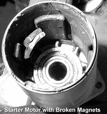
 Be gentle when handling a starter motor, especially
one with permanent magnets. Never abuse it by dropping it on the floor or
striking it with a heavy metal object, such as a hammer! Doing this could,
or most likely will, break the fragile
ceramic magnets inside the starter and render it totally
useless. Personally, I've
seen some people strike a starter motor with a hammer, thinking this will
fix it when it fails to operate. No joke.
Be gentle when handling a starter motor, especially
one with permanent magnets. Never abuse it by dropping it on the floor or
striking it with a heavy metal object, such as a hammer! Doing this could,
or most likely will, break the fragile
ceramic magnets inside the starter and render it totally
useless. Personally, I've
seen some people strike a starter motor with a hammer, thinking this will
fix it when it fails to operate. No joke.
 Most quality-made starter motors
are designed to last the life of the engine. Therefore, if a good starter
burns up prematurely, then this means that it has cranked the engine for
too long at one time. All 12 volt starters are actually 6 volt motors operating
on 12 volts of power. This is what gives them so much torque to crank the
engine so fast and with no effort. So if a starter motor is spun too long
(longer than 2 minutes), the excess voltage will burn up the wire windings
in the starter. The longer it's spun, the hotter it will get, which causes
the windings to get very hot, which causes the insulating/separating varnish
coating on the windings to melt. When the coating melts, the windings make
contact with each other and become shorted out, and you have a burned up
starter on your hands. That's why most owner's and repair manuals say to
never crank an engine longer than 2 minutes at a time without allowing adequate
time for the starter to cool before cranking it again. (If an engine won't
start within 2 minutes of cranking, then it obviously needs a major tune-up
or repair!) And unlike most automotive starters, which are in
big demand, nobody rebuilds (rewinds) Kohler starter motors.
Most quality-made starter motors
are designed to last the life of the engine. Therefore, if a good starter
burns up prematurely, then this means that it has cranked the engine for
too long at one time. All 12 volt starters are actually 6 volt motors operating
on 12 volts of power. This is what gives them so much torque to crank the
engine so fast and with no effort. So if a starter motor is spun too long
(longer than 2 minutes), the excess voltage will burn up the wire windings
in the starter. The longer it's spun, the hotter it will get, which causes
the windings to get very hot, which causes the insulating/separating varnish
coating on the windings to melt. When the coating melts, the windings make
contact with each other and become shorted out, and you have a burned up
starter on your hands. That's why most owner's and repair manuals say to
never crank an engine longer than 2 minutes at a time without allowing adequate
time for the starter to cool before cranking it again. (If an engine won't
start within 2 minutes of cranking, then it obviously needs a major tune-up
or repair!) And unlike most automotive starters, which are in
big demand, nobody rebuilds (rewinds) Kohler starter motors.
There's three things that can cause a good starter motor to burn up -
If you
would like to have a starter motor to crank your engine without hesitation,
you'd be better off purchasing a new one or one that's been professionally
rebuilt. Never put full trust in a used electric starter to crank your engine
unless your receive an unconditional guarantee that it's good. Otherwise,
there's a chance that it's either 90% wore out, burned up or the magnets
are broken, and the owner is just trying to sell "junk" to another person.
A starter may look nice and clean on the outside, but it's what's on the
inside that matters. Some of these questionable starters are sold "AS IS"
on places like eBay. So remember these words... "BUYER BEWARE!" By the way
- I'm not trying to sell you a new starter here, I'm only informing you of
the facts.
The Ultimate High Torque Gear Reduction Starter Motor and Bracket Assembly!
 Suitable for Kohler 10hp, 12hp,
14hp, 16hp and 18hp OHV Competition Pulling Engines. 12 volt negative ground.
This is an extremely powerful starter! It will not hesitate whatsoever
to crank over most Kohler K-series (or Magnum) single cylinder engines with
a machined high compression billet cylinder head and without an automatic
compression release (ACR) on the camshaft. Ideal for Hot-Stock, Stock-Altered,
30 c.i., 37c.i./16hp Missouri Super-Stock, and 50.5 c.i. Modified-Class single
cylinder competition pulling engines. Will also crank over an ordinary lawn
and garden Kohler engine with a non-working automatic compression release.
No need to use this starter on an engine with a working automatic compression
release (ACR). The starter gear will fit inside the OEM Kohler K-series flywheel
shroud. This starter has a built-in solenoid/relay; no need for a separate
solenoid.
Suitable for Kohler 10hp, 12hp,
14hp, 16hp and 18hp OHV Competition Pulling Engines. 12 volt negative ground.
This is an extremely powerful starter! It will not hesitate whatsoever
to crank over most Kohler K-series (or Magnum) single cylinder engines with
a machined high compression billet cylinder head and without an automatic
compression release (ACR) on the camshaft. Ideal for Hot-Stock, Stock-Altered,
30 c.i., 37c.i./16hp Missouri Super-Stock, and 50.5 c.i. Modified-Class single
cylinder competition pulling engines. Will also crank over an ordinary lawn
and garden Kohler engine with a non-working automatic compression release.
No need to use this starter on an engine with a working automatic compression
release (ACR). The starter gear will fit inside the OEM Kohler K-series flywheel
shroud. This starter has a built-in solenoid/relay; no need for a separate
solenoid.
The correct Toyota gear reduction starter motor to use are: 1986-1993 Toyota Celica, 1987-1994 Toyota Camry, 1989-1995 Toyota MR2, 1990-1991 Lexus ES250, and 1992-1994 Lexus ES300.
Requires a heavy duty CNC-machined billet aluminum adapter/mounting bracket, which is available on eBay. When engaged, if the starter gear teeth doesn't fully align with the flywheel gear teeth, the starter can be relocated by rearranging the two Allen screws in the aluminum billet starter bracket.
And due to the extreme outward pressure this high torque starter places on the side of the block of a high compression competition pulling engine to crank it over, it's recommended to fabricate and install a sturdy reinforcement support brace to prevent the possibility of block cracking or breakage. NOTES: Best to use a long reach hex bit (Allen) socket to fasten socket (Allen) head bolts to engine block. And due to the design of certain starter motors (listed below), part of the crankcase next to the lower cylinder may need to be ground away about 1/8" for clearance of the battery cable terminal.
How to Reassemble a Kohler Starter Motor -
 Before reassembling a Kohler
starter motor, first, a brush holder tool must be fabricated from sheet metal
to depress and retain the brushes in their cavities before the end cap can
be reinstalled onto the starter housing. Without this tool, it is nearly
impossible to install the end cap with the brushes depressed.
Before reassembling a Kohler
starter motor, first, a brush holder tool must be fabricated from sheet metal
to depress and retain the brushes in their cavities before the end cap can
be reinstalled onto the starter housing. Without this tool, it is nearly
impossible to install the end cap with the brushes depressed.
To properly install the end cap on the housing, align the projected tang inside the housing with the notch inside the end cap so the bolt holes will be aligned and so the terminal will be in the correct position. Install the bolts, then the brush holder tool can be pulled out and the brushes will snap against the commutator, and then tighten the bolts to 15 in. lb.
Widening the Frame/Chassis on a Narrow-Frame Cub Cadet Garden Tractor for use with a Large Flywheel and Gear Starter Motor - Top of Page
|
The upper mount gear starter (mounting bolts are below the starter motor)can't be installed on the very early K241 engine blocks because there's no indentation in the block just above the starter's mounting holes. These blocks were designed for the starter/generator only. |
Parts needed to convert a Kohler K-series engine with a starter/generator to a gear starter -
|
|
Parts needed to convert virtually any small gas engine to electric gear start -
|
|
Parts needed to convert a stand-alone Kohler K-series [welder or generator] engine models K241, K301, K321 or K341 with a manual recoil or rope starter to an electric gear starter system - (Added 9/13/18) [Top of Page]
| Parts off of a Kohler Magnum engine model M10, M12, M14 or M16 can be used. Parts needed are - flywheel w/plastic fan, starter motor, bearing plate, solid state ignition coil/module w/mounting screws and inner air baffle. These parts will interchange between the K241, K301, K321 and K341 engines. Also, these parts are hard to find nowadays because Kohler didn't make many Magnum single cylinder engines. The best to find these parts is on eBay, local small engine repair shops/salvage yards, Craigslist, visit antique/vintage swap meets/shows or search Google. |
Depending on battery drainage and need for recharging, to be precise, and with the engine running at 3,600 RPM, the generator part of the starter/generator unit or alternator stator uses a small percentage of engine horsepower when it recharges a fully discharged battery. But if the battery doesn't need much recharging, the charging system draws less horsepower from the engine. I know this small amount isn't much, but every horsepower counts in competitive pulling. So to reserve this power for pulling, disconnect the generator or alternator from charging the battery (and powering other electrical accessories as well) simply by splitting the wire that connects to the FIELD terminal (the smaller wire and terminal) on a starter/generator unit and splitting the wire that connects to the center terminal on the voltage rectifier/regular of an alternator system. Then connect an ordinary Grounded OFF/ON Toggle Switch in that wire or circuit to turn off and on the charging current. And it'll be best not to spin the starter/generator when pulling. Being it has ball bearings, the excessive spinning won't hurt it. But being the V-belt causes drag, depending on belt tension, it can use up to 2 horsepower of engine power just to spin it. This is also power that can be put to the rear tires for pulling. Besides, wouldn't it be better to spin the tires than the starter/generator? So to disengage the starter/generator belt, install threaded studs with locknuts on the starter/generator bracket and install a heavy spring on the starter/generator so it'll remain close to the engine. To crank the engine, install the belt on the pulleys, then pull out on the starter/generator with a fabricated handle to tighten the belt. After the engine starts, release the starter/generator and flip the belt off. But use caution doing this for an obvious reason!
Advertisement:
| Click here to contact A-1 Miller's Performance Enterprises to place an order, send your parts for repairing, and/or for FREE professional and honest technical customer service assistance and support and payment options. Please contact A-1 Miller's if you need a part or parts, or service(s) performed that's not listed or mentioned in this website. Prices are subject to change without notice. |
 High
Quality Small Engine Inductive Tachometer/Hour Meter with Replaceable
Battery. A tachometer is required for monitoring and/or setting the
maximum speed of a small engine, which is normally 3,200 or 3,600 RPM (depending
on type of carburetor), to prevent from over-revving and possible damage
to the engine or dangerous flywheel explosion. Very accurate, vibration-proof
and weatherproof construction. Can be surface-mounted and secured with two
screws to monitor engine RPM, or hand-held to set engine RPM. Large 3/8 inch
LCD display. Works with magneto or battery-powered ignition systems by selecting
engine type by programming S1 and S2 buttons. If tachometer does not turn
on automatically as soon as engine starts, press and hold the two buttons
at the same time. Instructions included. Reads up to 99,999 RPM. Hour
meter reads up to 9999:59 hours/minutes. Programmable maintenance hour setting
with service icon, a service reminder when to change oil or other maintenance.
Can be manually reset to Zero hours. Easy installation: Single wire wraps
around spark plug wire and secured with two supplied nylon zip-ties. No wire
terminal connections required. Includes replaceable CR2450 battery. Dimensions:
2" wide x 1-3/4" depth x 3/4" height. $25.00 each, plus shipping &
handling. Click here to print
out instructions. Please let me know if you're
interested in purchasing this item and I'll give you the total amount with
shipping and payment options. High
Quality Small Engine Inductive Tachometer/Hour Meter with Replaceable
Battery. A tachometer is required for monitoring and/or setting the
maximum speed of a small engine, which is normally 3,200 or 3,600 RPM (depending
on type of carburetor), to prevent from over-revving and possible damage
to the engine or dangerous flywheel explosion. Very accurate, vibration-proof
and weatherproof construction. Can be surface-mounted and secured with two
screws to monitor engine RPM, or hand-held to set engine RPM. Large 3/8 inch
LCD display. Works with magneto or battery-powered ignition systems by selecting
engine type by programming S1 and S2 buttons. If tachometer does not turn
on automatically as soon as engine starts, press and hold the two buttons
at the same time. Instructions included. Reads up to 99,999 RPM. Hour
meter reads up to 9999:59 hours/minutes. Programmable maintenance hour setting
with service icon, a service reminder when to change oil or other maintenance.
Can be manually reset to Zero hours. Easy installation: Single wire wraps
around spark plug wire and secured with two supplied nylon zip-ties. No wire
terminal connections required. Includes replaceable CR2450 battery. Dimensions:
2" wide x 1-3/4" depth x 3/4" height. $25.00 each, plus shipping &
handling. Click here to print
out instructions. Please let me know if you're
interested in purchasing this item and I'll give you the total amount with
shipping and payment options.
Wiring Instructions:
Wiring is the same for the hall effect and inductive proximity sensors. Certain proximity sensors have an LED (Light Emitting Diode), which flashes when in close proximity of target. If the proximity sensor is wired incorrectly, the LED will illuminate at all times. Click or tap here for YouTube videos to see how well this tachometer works.
|
   High Quality
Universal Self-Grounding OFF/ON Switches. Designed for use with
Self-Energizing Magneto Ignition, Solid State Ignition, OEM Solid State
Ignition (SSI) for Tecumseh's Cast Iron Block Engines, or with OEM Kohler
Breakerless Ignition. These can be used on virtually any small engine
installed on lawn and garden equipment, garden tillers, go-karts, chainsaws,
log splitters, portable air compressors, portable generators/welders, portable
water pumps, etc. with a magneto or solid state ignition, and a recoil/rope
starter or a push-button switch with an electric starter motor to crank the
engine. Very durable, tough switches. High Quality
Universal Self-Grounding OFF/ON Switches. Designed for use with
Self-Energizing Magneto Ignition, Solid State Ignition, OEM Solid State
Ignition (SSI) for Tecumseh's Cast Iron Block Engines, or with OEM Kohler
Breakerless Ignition. These can be used on virtually any small engine
installed on lawn and garden equipment, garden tillers, go-karts, chainsaws,
log splitters, portable air compressors, portable generators/welders, portable
water pumps, etc. with a magneto or solid state ignition, and a recoil/rope
starter or a push-button switch with an electric starter motor to crank the
engine. Very durable, tough switches.
|
 High Quality Universal OFF/ON Switches for Battery-Powered
Ignition and Electrical Accessories. Very durable, tough switches. Either
can be used for ignition, lights,
electric fuel
pump, electric PTO clutch, etc. When used for ignition, use with
push button starter switch (listed below). Terminals or wires on switches
listed below makes contact when in the ON position. Can be used on virtually
anything that have a battery-powered ignition or electrical system, such
as: garden tractors, go-karts, small motorized vehicles, competition pulling
tractors, mini-rods, hot-rods, farm tractors, automobiles, etc. Each can
be mounted in dashboard, instrument panel, engine control panel, etc. High Quality Universal OFF/ON Switches for Battery-Powered
Ignition and Electrical Accessories. Very durable, tough switches. Either
can be used for ignition, lights,
electric fuel
pump, electric PTO clutch, etc. When used for ignition, use with
push button starter switch (listed below). Terminals or wires on switches
listed below makes contact when in the ON position. Can be used on virtually
anything that have a battery-powered ignition or electrical system, such
as: garden tractors, go-karts, small motorized vehicles, competition pulling
tractors, mini-rods, hot-rods, farm tractors, automobiles, etc. Each can
be mounted in dashboard, instrument panel, engine control panel, etc.
|
 High
Quality Universal Push Button Switches. Each can be mounted in pedestal,
dashboard, instrument panel, engine control panel, flywheel shroud, etc. High
Quality Universal Push Button Switches. Each can be mounted in pedestal,
dashboard, instrument panel, engine control panel, flywheel shroud, etc.
|
 High Quality Universal 3-Position OFF-ON-START MAGNETO Ignition
Key Switch. Designed specifically for Self-Energizing Magneto Ignition,
Solid State Ignition, OEM Solid State Ignition (SSI) for Tecumseh's Cast
Iron Block Engines, or with OEM Kohler Breakerless Ignition. Can be used
for various makes and models of riding mowers, lawn & garden tractors,
garden tractors and various small engine equipment with magneto or solid
state ignition. Identification of 5 blade terminals: B = Battery (+);
G = Ground (terminal is grounded to body of switch); L = Lights
(use a separate OFF-ON switch connected to this terminal to power an electric
PTO clutch); M = Magneto (Ignition); S = Solenoid (small terminal).
Key positions: OFF position makes contact with M+G; IGNITION position makes
contact with B+L; START position makes contact with B+S. Each terminal identified
for correct wiring connections. IMPORTANT: Use with a starter solenoid/relay
to crank the engine to prevent burning out internal contacts in switch. NOTE:
If engine is equipped with an alternator/stator charging system, the center
terminal on the voltage rectifier/regulator connects to the positive (+)
battery post. If using an ammeter/amp gauge, connect the gauge/meter to the
positive (+) battery post, then to the B terminal on the switch. Trace the
wires on your tractor/equipment to see if they match the terminals on this
switch. If they don't match, the plug-in spade connectors/wires can be rearranged
in the plastic connector housing to match the corresponding terminals on
the switch. To do this, use a small flat blade screwdriver to depress the
locking tab/tang so the plug-in connector can be pulled out from the plastic
connector housing. Bend the locking tab/tang up slightly before reinserting
it in the plastic connector so it will be secured in place. Or for a universal
application, use #250
slip-on female spade crimp-type wire connectors. Requires
5/8" diameter mounting hole. High Quality Universal 3-Position OFF-ON-START MAGNETO Ignition
Key Switch. Designed specifically for Self-Energizing Magneto Ignition,
Solid State Ignition, OEM Solid State Ignition (SSI) for Tecumseh's Cast
Iron Block Engines, or with OEM Kohler Breakerless Ignition. Can be used
for various makes and models of riding mowers, lawn & garden tractors,
garden tractors and various small engine equipment with magneto or solid
state ignition. Identification of 5 blade terminals: B = Battery (+);
G = Ground (terminal is grounded to body of switch); L = Lights
(use a separate OFF-ON switch connected to this terminal to power an electric
PTO clutch); M = Magneto (Ignition); S = Solenoid (small terminal).
Key positions: OFF position makes contact with M+G; IGNITION position makes
contact with B+L; START position makes contact with B+S. Each terminal identified
for correct wiring connections. IMPORTANT: Use with a starter solenoid/relay
to crank the engine to prevent burning out internal contacts in switch. NOTE:
If engine is equipped with an alternator/stator charging system, the center
terminal on the voltage rectifier/regulator connects to the positive (+)
battery post. If using an ammeter/amp gauge, connect the gauge/meter to the
positive (+) battery post, then to the B terminal on the switch. Trace the
wires on your tractor/equipment to see if they match the terminals on this
switch. If they don't match, the plug-in spade connectors/wires can be rearranged
in the plastic connector housing to match the corresponding terminals on
the switch. To do this, use a small flat blade screwdriver to depress the
locking tab/tang so the plug-in connector can be pulled out from the plastic
connector housing. Bend the locking tab/tang up slightly before reinserting
it in the plastic connector so it will be secured in place. Or for a universal
application, use #250
slip-on female spade crimp-type wire connectors. Requires
5/8" diameter mounting hole.
|
  Universal Wiring Harness with Plastic Connector Housing
and Slide-On Connectors. Replace damaged entire connector, terminals
and wiring, use as new wiring harness on a custom-made project, or use this
part when converting from Breakerless Ignition to battery-powered
points/condenser ignition. Fits universal OFF-ON-START key switches listed
above and other key switches with same terminal configuration. Three terminals
in this part will also fit the OEM Cub Cadet garden tractor OFF-ON-START
key switch listed above. 18" length color-coded wires for easy identification.
$13.00 each, plus shipping & handling. Universal Wiring Harness with Plastic Connector Housing
and Slide-On Connectors. Replace damaged entire connector, terminals
and wiring, use as new wiring harness on a custom-made project, or use this
part when converting from Breakerless Ignition to battery-powered
points/condenser ignition. Fits universal OFF-ON-START key switches listed
above and other key switches with same terminal configuration. Three terminals
in this part will also fit the OEM Cub Cadet garden tractor OFF-ON-START
key switch listed above. 18" length color-coded wires for easy identification.
$13.00 each, plus shipping & handling.
Electrical Plastic Connector Housing Only. Replace damaged connector housing when the brass slide-on spade crimp wire connectors (listed below) are in good condition. Fits universal OFF-ON-START key switches listed above and other key switches with same terminal configuration. Three slots in this part will also fit the OEM Cub Cadet garden tractor OFF-ON-START key switch listed above. Requires 1/4" width slide-on brass spade crimp wire connectors with locking tab/tang below. $8.00 each, plus shipping & handling.
|
Amp Gauges, Voltage Regulators, Diodes, Voltage Rectifiers/Regulators, Charging Stators, and Internal Flywheel Charging Magnets - Click here to contact A-1 Miller's Performance Enterprises to place an order, send your parts for repairing, and/or for FREE professional and honest technical customer service assistance and support and payment options. Please contact A-1 Miller's if you need a part or parts, or service(s) performed that's not listed or mentioned in this website. [Top of Page] Advertisement:
 High Quality 20
and 30 Amp (Ammeter) Gauge Kits. Install an amp gauge to monitor exactly
what the charging system on your engine is doing. Having an amp gauge installed
is very important for monitoring the charging system to prevent premature
failure of electrical components. As battery becomes fully charged, needle
slowly moves from positive side (+) to zero (0). Needle will stay on negative
side (–) if no charge goes to the battery or if there is a discharge
(drain from the battery). Or gauge will not show any charge at all if charging
system is not working. With a working amp gauge, if the charging system continues
to charge to the plus (+) side with no gradual moving back of the needle
to zero while the engine is running at full governed speed, due to a faulty
voltage rectifier/regulator, this will send too much voltage to or overcharge
the battery, which could eventually burn up the cells in the battery, or
burn up the primary windings in a [battery] ignition coil, burn up an electric
PTO clutch, burn out light bulbs, the [battery powered] electronic ignition
control module (crank-trigger and
flywheel-trigger), and other electrical accessories. Connect the positive
(+) terminal on gauge to the battery positive (+) post or main junction
block/starter solenoid, and the negative (—) terminal on gauge to the
"A" terminal on the starter switch or BAT wire or terminal on the voltage
regulator or voltage rectifier/regulator, using heavy-gauge wire (10 or 12
AWG) to prevent overheating. Appearance of gauge may be different than shown
to the right. Each gauge kit listed below requires 2" mounting hole, and
replaces discontinued Kohler part # 48 755 18-S (45 amp). High Quality 20
and 30 Amp (Ammeter) Gauge Kits. Install an amp gauge to monitor exactly
what the charging system on your engine is doing. Having an amp gauge installed
is very important for monitoring the charging system to prevent premature
failure of electrical components. As battery becomes fully charged, needle
slowly moves from positive side (+) to zero (0). Needle will stay on negative
side (–) if no charge goes to the battery or if there is a discharge
(drain from the battery). Or gauge will not show any charge at all if charging
system is not working. With a working amp gauge, if the charging system continues
to charge to the plus (+) side with no gradual moving back of the needle
to zero while the engine is running at full governed speed, due to a faulty
voltage rectifier/regulator, this will send too much voltage to or overcharge
the battery, which could eventually burn up the cells in the battery, or
burn up the primary windings in a [battery] ignition coil, burn up an electric
PTO clutch, burn out light bulbs, the [battery powered] electronic ignition
control module (crank-trigger and
flywheel-trigger), and other electrical accessories. Connect the positive
(+) terminal on gauge to the battery positive (+) post or main junction
block/starter solenoid, and the negative (—) terminal on gauge to the
"A" terminal on the starter switch or BAT wire or terminal on the voltage
regulator or voltage rectifier/regulator, using heavy-gauge wire (10 or 12
AWG) to prevent overheating. Appearance of gauge may be different than shown
to the right. Each gauge kit listed below requires 2" mounting hole, and
replaces discontinued Kohler part # 48 755 18-S (45 amp).
|
|
 Analog 15 Amp
Voltage Regulator for 12 Volt Starter/Generators. If the charging system
continues to charge with no gradual moving back of the needle to zero on
an analog ammeter/amp gauge (if installed) while the
engine is running, this will put too much voltage throughout the entire
electrical system, which could eventually burn up the ignition coil, battery,
burn out light bulbs, burn up the electric PTO clutch, burn up the electronic
ignition control module (crank trigger ignition)
and burn up the any other electrical components. With the terminals facing
you, they read: L = Lights | Bat = Battery | F = Field, A = Armature (on
the bottom). L connects to the Lights (if equipped); Bat connects to the
ignition switch, which connects to the battery positive (+) post; F connects
to the Field terminal on the starter/generator; and A connects to the Armature
terminal on the starter/generator. The frame of the regulator must be securely
grounded to the engine, tractor or equipment through the mounting bolts,
which connects to the battery negative (–) post. NOTE: Cannot be
substituted for use with the alternator/stator charging system. Analog 15 Amp
Voltage Regulator for 12 Volt Starter/Generators. If the charging system
continues to charge with no gradual moving back of the needle to zero on
an analog ammeter/amp gauge (if installed) while the
engine is running, this will put too much voltage throughout the entire
electrical system, which could eventually burn up the ignition coil, battery,
burn out light bulbs, burn up the electric PTO clutch, burn up the electronic
ignition control module (crank trigger ignition)
and burn up the any other electrical components. With the terminals facing
you, they read: L = Lights | Bat = Battery | F = Field, A = Armature (on
the bottom). L connects to the Lights (if equipped); Bat connects to the
ignition switch, which connects to the battery positive (+) post; F connects
to the Field terminal on the starter/generator; and A connects to the Armature
terminal on the starter/generator. The frame of the regulator must be securely
grounded to the engine, tractor or equipment through the mounting bolts,
which connects to the battery negative (–) post. NOTE: Cannot be
substituted for use with the alternator/stator charging system.
|
|
   Two Wire Rectifier
Diodes. The 3- and 4-amp diodes can be used in a 12 volt non-regulated small
engine alternator/stator charging system to convert alternating current (AC)
to direct current (DC) to recharge the battery and/or power low-amperage
DC electrical accessories, such as LED lights, small electric motors, etc.
A diode is not required for
filament light bulbs, fluorescent and/or an electric PTO
clutch. The 1 amp diode can be used on an engine with a small charging coil
next to the magneto ignition coil on the stator to energize the field windings
in a direct-drive 120/240 volt AC portable generator powered by a small engine
or for a belt-driven
automotive alternator that's powered by a small engine so the
alternator/generator will produce electricity as soon as the engine starts.
IMPORTANT - Install the diode with the silver stripe toward the generator's
field windings. And do not overload the amperage of the diode or it may burn
up. Two Wire Rectifier
Diodes. The 3- and 4-amp diodes can be used in a 12 volt non-regulated small
engine alternator/stator charging system to convert alternating current (AC)
to direct current (DC) to recharge the battery and/or power low-amperage
DC electrical accessories, such as LED lights, small electric motors, etc.
A diode is not required for
filament light bulbs, fluorescent and/or an electric PTO
clutch. The 1 amp diode can be used on an engine with a small charging coil
next to the magneto ignition coil on the stator to energize the field windings
in a direct-drive 120/240 volt AC portable generator powered by a small engine
or for a belt-driven
automotive alternator that's powered by a small engine so the
alternator/generator will produce electricity as soon as the engine starts.
IMPORTANT - Install the diode with the silver stripe toward the generator's
field windings. And do not overload the amperage of the diode or it may burn
up.
FYI - Briggs & Stratton engines have either one or two OEM alternator stators and they are joined together in two half circles under the flywheel. Some engines only come with one half stator. Each half produce 3 amps of power & 14 volts @ 3,600 RPM. If an engine comes with two stators joined together, one half produces AC, which is used to power the lights and electric PTO clutch. And the other half also produce AC, but is connected to a minimum 3 amp/14 volt diode, which is used to only recharge the battery. Under normal yard use, 3 amps is not enough to overcharge and burn up the battery. If both stator halves are wired together from the factory (as they are on certain engines), they will produce 6 amps of AC power and a 6 amp electronic/solid state voltage rectifier/regulator is used to power the lights, electric PTO clutch and recharge the battery. |
|
 Electronic/Solid
State Voltage Rectifier/Regulator for Old Style 10 Amp Output 12 Volt Alternator
Charging Stators (listed below). If the charging system continues to generate
full charge with no gradual moving back of the needle to zero on an analog
ammeter/amp gauge (if installed) while the engine
is running, the excessive overcharging may eventually burn out the primary
windings in the ignition coil, burn up the electronic ignition control module
(crank trigger), burn up the battery, burn
out light bulbs, electric PTO clutch, and any other electrical accessories.
These will also work with virtually any 15 or 20 amp small engine
alternator/stator charging system. Orientation of terminals are "three in
a row" (AC | BAT+ | AC). NOTE: Cannot be substituted for use with the
starter/generator charging system. FYI: After many years of use and
for reasons unknown (even to me), the old-style 10 amp charging system is
notorious for generating very few amps, about 3 amps more or less maximum
at full governed engine speed, and I have no idea why. I believe this is
why the 10 amp stator was a short-lived item that was discontinued from Kohler
and replaced with the more reliable 15 or 20 amp stator charging system,
which works much better and is still in use on many makes and models of small
engines today. So if your engine has the 10 amp charging system and it only
generates a few amps, it may need to be upgraded with the new-style 15 or
20 charging system. Electronic/Solid
State Voltage Rectifier/Regulator for Old Style 10 Amp Output 12 Volt Alternator
Charging Stators (listed below). If the charging system continues to generate
full charge with no gradual moving back of the needle to zero on an analog
ammeter/amp gauge (if installed) while the engine
is running, the excessive overcharging may eventually burn out the primary
windings in the ignition coil, burn up the electronic ignition control module
(crank trigger), burn up the battery, burn
out light bulbs, electric PTO clutch, and any other electrical accessories.
These will also work with virtually any 15 or 20 amp small engine
alternator/stator charging system. Orientation of terminals are "three in
a row" (AC | BAT+ | AC). NOTE: Cannot be substituted for use with the
starter/generator charging system. FYI: After many years of use and
for reasons unknown (even to me), the old-style 10 amp charging system is
notorious for generating very few amps, about 3 amps more or less maximum
at full governed engine speed, and I have no idea why. I believe this is
why the 10 amp stator was a short-lived item that was discontinued from Kohler
and replaced with the more reliable 15 or 20 amp stator charging system,
which works much better and is still in use on many makes and models of small
engines today. So if your engine has the 10 amp charging system and it only
generates a few amps, it may need to be upgraded with the new-style 15 or
20 charging system.
|
|
|
|
 1/4" Width Slide-On Brass
Spade Crimp Wire Connector with Locking Tab/Tang. Replace damaged brass
connector(s) to insure 100% electrical connections. Fits plastic housing
electrical connectors used on most Off-Ignition-Start key switches, voltage
rectifier/regulators, head lights, etc. FYI - Solder or use
terminal crimping pliers to secure new brass connector
on wire. To remove old slide-on brass connector from plastic housing, depress
locking tab/tang on connector from the wire end with a small flat blade
screwdriver, and pull connector out of housing. Before installing the new
connector, make sure locking tab/tang is slightly bent outward, and then
slide connector into plastic housing in the correct position until it locks/snaps
in place. This part was never available separately from Kohler.
$1.40 each, plus shipping & handling. 1/4" Width Slide-On Brass
Spade Crimp Wire Connector with Locking Tab/Tang. Replace damaged brass
connector(s) to insure 100% electrical connections. Fits plastic housing
electrical connectors used on most Off-Ignition-Start key switches, voltage
rectifier/regulators, head lights, etc. FYI - Solder or use
terminal crimping pliers to secure new brass connector
on wire. To remove old slide-on brass connector from plastic housing, depress
locking tab/tang on connector from the wire end with a small flat blade
screwdriver, and pull connector out of housing. Before installing the new
connector, make sure locking tab/tang is slightly bent outward, and then
slide connector into plastic housing in the correct position until it locks/snaps
in place. This part was never available separately from Kohler.
$1.40 each, plus shipping & handling. |
 Plastic Housing Electrical
Connector. Fits old style 10 amp and new style 15/20 amp voltage
rectifier/regulators (listed below). Replace damaged/melted connector when
the brass slide-on spade crimp wire connectors are in good condition. Requires
1/4" width slide-on brass spade crimp wire connector with locking tab/tang.
OEM Kohler part # 25 155 41-S. $5.20 each, plus shipping & handling. Plastic Housing Electrical
Connector. Fits old style 10 amp and new style 15/20 amp voltage
rectifier/regulators (listed below). Replace damaged/melted connector when
the brass slide-on spade crimp wire connectors are in good condition. Requires
1/4" width slide-on brass spade crimp wire connector with locking tab/tang.
OEM Kohler part # 25 155 41-S. $5.20 each, plus shipping & handling. |
 Electronic/Solid
State Voltage Rectifiers/Regulators for New-Style 12 Volt 15/20 Amp Output
Alternator/Stator Charging Stators (listed below). If the charging system
continues to charge with no gradual moving back of the needle to zero on
an analog ammeter/amp gauge (if installed) while the
engine is running, this will put too much voltage throughout the entire
electrical system, which could eventually burn up the ignition coil, battery,
burn out light bulbs, burn up the electric PTO clutch, burn up the electronic
ignition control module (crank trigger ignition)
and burn up the any other electrical components. Each listed below work the
same. These voltage rectifier/regulators are small, compact and have the
same mounting hole spacing, and fit many 8 thru 24hp Kohler engine models
with a 15 or 20 amp alternator/stator charging stator under the flywheel.
For various makes and models of small engines with a 30 amp stator, instead
of using a 30 amp NOS (and high dollar) replacement voltage rectifier/regulator
(discontinued Kohler part # 277063-S), two 15/20 amp voltage
rectifiers/regulators wired in parallel can be used. Each listed below mounts
in the rectangular hole in the Kohler flywheel shroud with ribs facing the
flywheel for better cooling of the unit. If it's mounted elsewhere with no
cool air blowing over it, it could overheat and prematurely burn up. These
can be substituted for use on virtually any 15 or 20 amp garden tractor,
motorcycle, etc., alternator/stator charging system. Orientation of terminals
are "three in a row" (AC - BAT+ - AC). NOTE: These cannot be substituted
for use with the starter/generator charging system. Electronic/Solid
State Voltage Rectifiers/Regulators for New-Style 12 Volt 15/20 Amp Output
Alternator/Stator Charging Stators (listed below). If the charging system
continues to charge with no gradual moving back of the needle to zero on
an analog ammeter/amp gauge (if installed) while the
engine is running, this will put too much voltage throughout the entire
electrical system, which could eventually burn up the ignition coil, battery,
burn out light bulbs, burn up the electric PTO clutch, burn up the electronic
ignition control module (crank trigger ignition)
and burn up the any other electrical components. Each listed below work the
same. These voltage rectifier/regulators are small, compact and have the
same mounting hole spacing, and fit many 8 thru 24hp Kohler engine models
with a 15 or 20 amp alternator/stator charging stator under the flywheel.
For various makes and models of small engines with a 30 amp stator, instead
of using a 30 amp NOS (and high dollar) replacement voltage rectifier/regulator
(discontinued Kohler part # 277063-S), two 15/20 amp voltage
rectifiers/regulators wired in parallel can be used. Each listed below mounts
in the rectangular hole in the Kohler flywheel shroud with ribs facing the
flywheel for better cooling of the unit. If it's mounted elsewhere with no
cool air blowing over it, it could overheat and prematurely burn up. These
can be substituted for use on virtually any 15 or 20 amp garden tractor,
motorcycle, etc., alternator/stator charging system. Orientation of terminals
are "three in a row" (AC - BAT+ - AC). NOTE: These cannot be substituted
for use with the starter/generator charging system.
|
|
   Electronic/Solid
State Voltage Rectifiers/Regulators for New-Style 12 Volt 15/20 Amp Output
Alternator Charging Stators (listed below). If the charging system continues
to charge with no gradual moving back of the needle to zero on an analog
ammeter/amp gauge (if installed) while the engine
is running, this will put too much voltage throughout the entire electrical
system, which could eventually burn up the ignition coil, battery, burn out
light bulbs, burn up the electric PTO clutch, burn up the electronic ignition
control module (crank trigger ignition) and
burn up the any other electrical components. Each listed below work the same.
Each have same mounting holes and fit many 8 thru 24hp Kohler engines with
a 15 amp alternator charging stator under the flywheel. These can be substituted
for use on virtually any 15 or 20 amp garden tractor, motorcycle, etc.,
alternator/stator charging system. The "two over, one under offset" plastic
wiring connector no longer available from Kohler. NOTE: Cannot be substituted
for use with the starter/generator charging system. Electronic/Solid
State Voltage Rectifiers/Regulators for New-Style 12 Volt 15/20 Amp Output
Alternator Charging Stators (listed below). If the charging system continues
to charge with no gradual moving back of the needle to zero on an analog
ammeter/amp gauge (if installed) while the engine
is running, this will put too much voltage throughout the entire electrical
system, which could eventually burn up the ignition coil, battery, burn out
light bulbs, burn up the electric PTO clutch, burn up the electronic ignition
control module (crank trigger ignition) and
burn up the any other electrical components. Each listed below work the same.
Each have same mounting holes and fit many 8 thru 24hp Kohler engines with
a 15 amp alternator charging stator under the flywheel. These can be substituted
for use on virtually any 15 or 20 amp garden tractor, motorcycle, etc.,
alternator/stator charging system. The "two over, one under offset" plastic
wiring connector no longer available from Kohler. NOTE: Cannot be substituted
for use with the starter/generator charging system.
|
|
|
|
How to Fix a Briggs & Stratton Opposed Twin Cylinder Engine Starter Motor When the Gear Teeth Will Not Fully Engage in the Flywheel Ring Gear Teeth -

Information About Various Starter Motors and Charging Systems - (Added 7/25/26) [Top of Page]
A 12 volt small engine gear starter and starter/generator typically produces between 0.5 to 1.5 horsepower to crank an average engine. Because of the automatic compression release (ACR) in later model engines, small engine starters do not need huge horsepower. Their main job is just to spin the engine fast enough so it can start on its own.
A 12 volt automotive starter motor, on the other hand, produces between 1.5 to 3.0 horsepower to crank an average automotive engine. Larger heavy-duty diesel engines can require more power and use starters that produce up to 15 horsepower. Think of the starter motor like a sprinter at the start of a race. It does not need to run for a long distance. Instead, it needs a quick burst of extreme strength to get the engine spinning over quickly so it will start.
The Charging System -
A 12 volt small engine starter/generator and alternator system absorbs about 3/8 to 7/8 horsepower from the engine at full charge (to recharge the battery while powering all electrical accessories) when the engine is running at 3,600 RPM. The exact amount of power required depends on the charging rate, amount of electrical accessories and engine speed: a 15 amp charging system draws about 3/8 hp; a 20 amp charging system draws approximately 5/8 hp, and a 30 amp charging system draws approximately 7/8 hp. If an automotive-style 60-amp to 100-amp alternator is used with a small engine, the horsepower drain is higher. At full load, a 60-amp alternator draws about 1.4 horsepower from the engine. A 100-amp alternator can take up to 3 horsepower from the engine.
The charging load on the engine drops as the battery gets full. When a 12-volt battery reaches full capacity, as the result of the voltage regulator (used with a starter/generator) or voltage rectifier/regulator (used with an alternator system), the generator or alternator stops pushing high amps and goes into a low "maintenance" mode. In this state, the charging system produces very little electricity, the power draw on the small engine drops to almost zero while maintaining full battery voltage, the charging system powers all the electrical accessories, and does not draw any power from the battery.
Information on the Kohler (Including Most Other Makes and Models of Small Engines) Charging Systems - [Top of Page]
First of all, the battery's only purpose in virtually any vehicle is to provide power to the starter motor to crank the engine and power electrical accessories when the engine isn't running. When the engine is running, and while the battery is being recharged, the alternator/stator or generator then powers the electrical accessories through the electronic/solid state voltage rectifier/regulator. With the engine running, and with a good working charging system, the battery has nothing to do with powering the electrical accessories. The ignition system also have nothing to do with the charging system. It's only purpose is to provide spark to the engine. The charging system and ignition system are two totally separate systems. One has nothing to do with the other, other than the charging system provides power to the battery-powered ignition system. A magneto or electronic/solid state ignition is a stand-alone system. It does not depend on the battery or charging system whatsoever.
The Generator/Starter Charging System -
 The voltage-producing
generating part of a starter/generator (or just the generator unit in an
older automobile or heavy equipment machinery) produces DC (direct current)
electricity. These are belt-driven and require a mechanical voltage regulator
to regulate the charge to the battery and power electrical accessories (such
as lights, electric PTO clutch, etc.) at the same time. The faster the engine
runs, the more voltage and amperage the generator produces. And unlike a
belt-driven automotive-type alternator, the generator is self-energizing.
It will produce its own electricity when spun fast enough. A charged battery
is not required.
The voltage-producing
generating part of a starter/generator (or just the generator unit in an
older automobile or heavy equipment machinery) produces DC (direct current)
electricity. These are belt-driven and require a mechanical voltage regulator
to regulate the charge to the battery and power electrical accessories (such
as lights, electric PTO clutch, etc.) at the same time. The faster the engine
runs, the more voltage and amperage the generator produces. And unlike a
belt-driven automotive-type alternator, the generator is self-energizing.
It will produce its own electricity when spun fast enough. A charged battery
is not required.
Although bulky, heavy and uses more space next to the engine, this system is reliable, but produce little- to no-charge at low idle speeds and are considered obsolete by today's standards. Also, this system require more horsepower from the engine than the alternator/stator system while recharging the battery and/or under a heavy electrical load.
I don't rebuild starter/generators. A business that specializes in rebuilding automotive starters, alternators and generators can also rebuild starter/generators. Or, you can purchase a new or used starter/generator off of eBay.
On certain starter/generators and for identification purposes only, the "A" (Armature) terminal stud may be bigger (number #12) than the "F" (Field) terminal stud (number #10). IMPORTANT - If the wires for the Armature and Field are connected in reverse, the field windings will burn up instantly (lots of smoke) upon engine start up! Always use stranded wire with crimp connectors for best results. The correct wiring connections for the starter/generator are as follows...
 A 6 or 8 gauge wire connects
from one of the big terminals on the heavy duty starter switch or starter
solenoid to the battery positive (+) post.
A 6 or 8 gauge wire connects
from one of the big terminals on the heavy duty starter switch or starter
solenoid to the battery positive (+) post.
A starter/generator can be adapted to virtually any horizontal shaft or vertical shaft small engine with a fabricated mounting bracket and a slotted adjusting brace to tighten the belt. The starter/generator will need to be installed opposite the carburetor side of the block. They come in two rotations: clockwise and counter-clockwise. Starter/generators that spin clockwise came on older Wheel Horse, Sears Suburban, Bolens, or any engine that's started from the flywheel end. A counter-clockwise starter/generator came mostly on older Cub Cadets, or any engine that's started from the PTO end. A clockwise rotation starter/generator will need to be used if it's driven from the flywheel end. But if it's driven from the PTO end, it will need to be a counter-clockwise rotation starter/generator. If the wrong starter/generator is used, it'll crank the engine opposite of normal rotation, and not recharge the battery.
If a starter/generator is belt-driven by an engine and used only as a generator to charge up a vehicle's battery and/or power 12 volt appliances or lights, the heavy battery cable won't need to be used. And there's about a 3:1 ratio between the starter/generator and engine. This means the starter/generator spins about 3 times faster than the engine. So the pulley on the engine will need to be about 3 times bigger than the pulley on the starter/generator to adequately recharge a battery and/or power 12 volt electrical appliances or lights. A starter/generator require a minimum 7/16 horsepower engine running at a governed 3,600 RPM for it to produce a regulated 15 amps @ 13.5 volts. (15 amps x 13.5 volts = 202.5 watts x 2 = 405 = .4hp engine.) Read on the back label of the appliance you plan to use for how many amps it draws, then you'll know if the generator will be able to handle the load.
But on a pulling tractor, if the engine isn't going to have a charging system, a voltage regulator and wiring isn't required as long as the battery is fully charged with a battery charger before the engine is ran again. Plus, the battery will need to be in a secure place, and route the wiring in a safe manner. Go here to learn how to repair a Delco-Remy starter/generator: Delco-Remy SG Repair.pdf. (require Adobe Acrobat Reader and use Google Chrome web browser for a faster download of web sites with large files.)
The Small Engine Alternator/Stator Charging Systems -
Kohler used six different models of stators on their engines. They are rated at 1.25 amp, which is used only to charge the battery; 3 amp, which is used to charge the battery and supply power for lights and/or an electric PTO clutch; and the 10, 15, 25 and 30 amp output stators, which are used to charge the battery and power heavier electrical loads. And all electric PTO clutches draw 3 amps of power, so the 3 amp output stator is required for these.
 The 1.25 and 3 amp stators doesn't
require an electronic/solid state voltage rectifier/regulator to regulate
the power to recharge the battery because for normal use, an average lawn
and garden engine don't run long enough for the 1.25 and 3 amp stators to
over-charge the battery, or over-power (burn out) the lights and/or an electric
PTO clutch. Instead, these use a rectifier diode to convert alternating current
(AC) to direct current (DC). The low 1.25 and 3 amp output stators require
a rectifier diode to convert the electrical Alternating
Current (AC) to Direct Current (DC) only to recharge the battery.
Filament lights and electric PTO clutches don't require direct current, so
they can operate without a diode.
The 1.25 and 3 amp stators doesn't
require an electronic/solid state voltage rectifier/regulator to regulate
the power to recharge the battery because for normal use, an average lawn
and garden engine don't run long enough for the 1.25 and 3 amp stators to
over-charge the battery, or over-power (burn out) the lights and/or an electric
PTO clutch. Instead, these use a rectifier diode to convert alternating current
(AC) to direct current (DC). The low 1.25 and 3 amp output stators require
a rectifier diode to convert the electrical Alternating
Current (AC) to Direct Current (DC) only to recharge the battery.
Filament lights and electric PTO clutches don't require direct current, so
they can operate without a diode.
Troubleshooting a 3 Amp Battery Charging System with the 70 Watt Lighting/Electric PTO Clutch Stator -
Certain Kohler engines with the 1.25 or 3 amp stator use a diode and not a voltage rectifier/regulator. To find out why one of these charging systems isn't generating any power, remove the flywheel and see if any of the magnets inside the flywheel are cracked, loose or missing. Next, check to see if the windings on the stator are burned up or damaged. If they are not burned up or damaged, then they should be in good condition. But to make sure, use a multimeter set on the Ohms resistance, connect the black wire on the meter to engine ground. and connect the red wire on the meter to the BLACK wire coming from the stator, then connect the YELLOW wire. If the meter shows continuity for either wire, then the windings are in good condition. But if there's no continuity, then there's a break (open circuit) in either windings to ground . The windings either needs to be repaired or the stator needs to be replaced. If all of this looks good, and either charging system still will not generate a charge to the battery, then chances are, the diode was overloaded and got burned up, and needs replacing. The diode is part of the BLACK wire coming from the stator, and there should be a "lump" in the BLACK wire. This is where the diode is located. It's probably covered with the plastic sheath and/or heat shrinkable tubing. You can replace it with a 3 amp/12 volt diode. Be sure to install the diode with the silver stripe toward the stator.
But the high-output stators (10, 15, 25, 30 amp or more), rather it's a charging stator under the flywheel on a small engine or belt-driven automotive-type alternator, require an electronic/solid state voltage "rectifier/regulator" to convert the alternating current (AC) to direct current (DC) and to regulate the amount of charge into the battery and limit the amount of voltage throughout the entire electrical system while powering electrical accessories at the same time. The faster the engine runs, the more voltage and amperage the stator produces.
Although very reliable, weather-proof and virtually maintenance-free, this system produces an adequate charge at low idle speeds.
This system is the standard of today's charging systems used on virtually all small engines, motorcycles, snowmobiles, automotive engines, heavy equipment machinery, etc.
And unlike the belt-driven automotive-type alternator, an alternator/stator under the flywheel is self-energizing. It will produce electricity when the flywheel is spun fast enough.
How to Identify the Three Wires Coming from an Engine -
Use a digital or analog multimeter set on the ohms (d) resistance to test each wire coming from the engine. With the engine not running, ground one test lead to the engine, and connect the other lead to each wire one at a time. If one wire shows resistance, this is the ignition kill wire. If the engine has points, the crankshaft may need to be rotated by hand until the wire shows resistance. (This is when the points close.) And if the other two wires show no resistance, these are the charging stator lead wires. When the test leads are connected to the two wires with no resistance, they should show 100% resistance. These two wires connect to the voltage regulator/rectifier. Be sure to mark each wire with masking tape or something to identify them.
How to Test the Condition of a Small Engine Alternator Charging Stator - [Top of Page]
First of all, all charging stators produce alternating current (AC) voltage and there's a diode built into the electronic/solid state voltage rectifier/regulator. (Rectifier = converts alternating current (AC) to direct current (DC); Regulator = regulates voltage to recharge the battery and limits power to electrical accessories, such as lights, electric PTO clutch, etc.) If the diode is shorted, it'll drain the battery and may burn up the stator windings. The wire windings on the stator are not grounded, they're isolated from the engine block. And debris/dirt on the stator or on the magnets in the flywheel do not weaken the magnetism to the stator whatsoever. Stators rarely become defective, unless the two wires are connected to each other while the engine is running, causing a short.
To test the condition of a stator with the engine not running, or with the stator removed from the engine (check to see of there's any wire windings on the stator that's damaged or broken from being mishandled), use an analog or digital multimeter set on ohms (d) resistance. Disconnect the two wires from the voltage rectifier/regulator, connect one stator wire to one test lead and connect the other test lead to the metal frame of the stator or engine block (installed stator). Notice the reading, and then do the same for the other stator wire. The meter should show no resistance with either wire. Then connect the two wires on the stator to the test leads on the meter. If the meter shows full resistance, the stator is likely in good condition. This testing procedure applies to all makes and models of small engines, including motorcycles and snowmobiles, foreign or domestic, with the charging stator located under the flywheel.
To test the voltage output of a stator with the engine running, use an analog or digital multimeter set at more than 36 volts in the AC setting. With the engine running at full governed speed set at 3,600 RPM, for a (4-5/8" O.D.) 10 amp stator, the reading should be in the range of 20 volts. For a (5-1/2" O.D.) 15 amp stator, the reading should be in the range of 28 volts. For a (5-1/2" O.D.) 20 amp stator, the reading should be in the range of 36 volts. If it's less than 20, 28 or 36 volts (according to the amperage of the stator), the stator may be defective and should either be repaired (if possible) or replaced. Or maybe a ceramic magnet inside the flywheel is cracked, or on a rare occasion, magnet(s) may be missing (wrong type of flywheel installed on the engine). A magnet with a chip should work fine, as long as it's not cracked or broken in two. Anyway, when testing the voltage output of a stator, if the reading is more than 20, 28 or 36 volts, the windings may be shorted (making contact with each other), resulting in the excessive increase of voltage, which would likely cause the voltage rectifier/regulator go bad, and possibly also burn up the acid in the battery, primary windings in the ignition coil and/or overpower electrical accessories. This test procedure applies to all makes and models of small engines, gas or diesel, including motorcycles and snowmobiles, foreign or domestic, with the charging stator located under the flywheel.
 Do not touch the
two wire terminals or the energizing coils wire on the stator with your bare
hands while the engine is running! Electrical shock or electrocution could
result!
Do not touch the
two wire terminals or the energizing coils wire on the stator with your bare
hands while the engine is running! Electrical shock or electrocution could
result!
How to Test an Electronic/Solid State Voltage Rectifier/Regulator -
The easiest and most accurate way to test an electronic/solid state voltage rectifier/regulator is with an analog or digital multimeter set in the DC setting above 12 volts, and with a known good charging stator installed in an engine while the engine is running. With the engine off, connect the stator's two wires to the rectifier/regulator's two outer terminals (being it's AC, it doesn't matter which wire connects to which terminal). With the engine running at 3,200 RPM (when the engine has a fixed/non-adjustable main jet carburetor) or 3,600 RPM (when the engine has an adjustable main jet carburetor), check the voltage output at the center terminal on the rectifier/regulator. If the voltmeter displays or reads 14.5 volts, the rectifier/regulator is good. If less than 14.5 volts or no voltage, the rectifier/regulator is defective. By the way - the older rectifier/regulator with fins works the same as the newer ones with no fins. Also, the small size voltage rectifier/regulator is to be mounted in the opening of the flywheel shroud of a Kohler AQS (Quiet Line) engine so cool incoming air from the flywheel will keep the regulator unit from overheating while in operation. If it's mounted elsewhere with no cool air blowing over it, it could burn up prematurely.
Make sure the slip-on spade crimp connectors on the stator's wires are in good condition and fit snug on the terminals of the electronic/solid state voltage rectifier/regulator. If the scrimp connectors fit loose or have a faulty connection due to rust, they could arc during heavy charging and burn out the terminal(s) on the voltage rectifier/regulator, and/or heat from the arcing could travel inside the voltage rectifier/regulator and burn it out.
Go here for more information:
The rectifier-regulator must match
the amperage output of the stator it's connected to. If a 15 amp
rectifier/regulator is used with a 25 or 30 amp stator, the rectifier/regulator
will burn up. A 32 amp electronic/solid state voltage rectifier/regulator
that's designed for Harley-Davidson motorcycles will work with the Kohler
30 amp stator. The starter/generators and voltage regulators used on all
garden tractors are rated at 15 amps. And an analog voltage regulator can't
be used with an AC alternator stator, nor the electronic voltage
rectifier/regulator can't be used with a DC generator.
To connect an alternator stator... the two leads from the stator connects to the two outer terminals on the rectifier-regulator. The center terminal on the rectifier-regulator then connects to the battery's + post or the ignition switch that connects to the battery's + post. It's that simple. And the electronic/solid state voltage rectifier/regulator has diodes built-in. So there's no need to add diodes in the circuit.
How to Replace the Charging Stator on a Kohler engine -
Converting the old starter/generator charging system to the newer, alternator-equipped charging system -
First off, all of the K241-K361 Kohler flywheels will interchange. The crankshaft tapers are the same. They're the same weight, too. The alternator stator-type charging system will also work on a narrow frame Cub Cadet, but the tractor frame rails must be widened to accept the larger diameter flywheel, bearing plate and shroud. The larger bearing plate will accept the stator/charging ring. And you'll need an electronic/solid state voltage rectifier/regulator that's capable of handling the amount of amps that the stator will produce. Stators installed on most Kohler engines have a 15, 20, 25 or 30 amp output. Most common are the 15 or 20 amp stators.

To identify the amount of amps a stator can produce...
If an electronic/solid state voltage rectifier/regulator that's made for a smaller [amperage] output is used with a higher amp output stator, it'll burn up in no time. Remember, the higher the amperage of a charging system, the more horsepower it'll draw from the engine (when under a heavy charging load). For wiring diagrams of various Cub Cadets, see this web site: http://www.ihregistry.com/ref/wire.htm. Refer to the Kohler K-Series Single Cylinder Engine Service Manual TP-2379, Kohler Magnum Single Cylinder Engine Service Manual TP-2203-A, Kohler KT17, KT17 series 2, KT19, KT19 series 2, KT21 Service Manual TP-2043-A, Kohler M18, M20 Service Manual TP-2204-B, Kohler MV16, MV18, MV20 Service Manual TP-2289-A or Kohler K482, K532, K582 & K662 Service Manual ENS-607 for more information on charging systems. (Requires Adobe Acrobat Reader and use Google Chrome web browser for a faster download of web sites with large files.)
How to Reinstall or Replace the Charging Magnets in a Kohler or Tecumseh Flywheel - [Top of Page]
 Kohler used to install aluminum
expansion roll pins to secure the ceramic magnets inside the flywheel. Which
worked very well. Then they dropped this design and glued them in instead.
Now people are having problems with the magnets coming loose. And sometimes
the loose magnets will damage the stator. Anyway, when a magnet becomes loose
inside the flywheel, if it is not broken, it can be reinstalled with
Krazy Glue,
Super Glue,
Gorilla Glue, or any industrial strength adhesive. Broken
magnets cannot be reused. A broken magnet must be replaced with an identical
magnet in good condition. A broken magnet actually becomes two magnets
with a north and south magnetic pole on each broken piece, and will not work
at all in a small engine alternator/stator charging system. Even if the two
pieces are glued together, the magnetic poles may or may not attract, and
the molecules cannot bond together to form one single magnet.
Kohler used to install aluminum
expansion roll pins to secure the ceramic magnets inside the flywheel. Which
worked very well. Then they dropped this design and glued them in instead.
Now people are having problems with the magnets coming loose. And sometimes
the loose magnets will damage the stator. Anyway, when a magnet becomes loose
inside the flywheel, if it is not broken, it can be reinstalled with
Krazy Glue,
Super Glue,
Gorilla Glue, or any industrial strength adhesive. Broken
magnets cannot be reused. A broken magnet must be replaced with an identical
magnet in good condition. A broken magnet actually becomes two magnets
with a north and south magnetic pole on each broken piece, and will not work
at all in a small engine alternator/stator charging system. Even if the two
pieces are glued together, the magnetic poles may or may not attract, and
the molecules cannot bond together to form one single magnet.
When the flywheel is removed and all the magnets are stuck to the stator, remove the magnets and place them someplace where so they're be in the order that they were in the flywheel or on the stator (don't mix them up). Thoroughly clean the outside curve of each magnet and the inside of the flywheel with electrical contact cleaner, brake parts cleaner, cleaning solvent or paint thinner (these leave no oily residue), and then reinstall the magnets in the order they were removed with Krazy Glue, Super Glue, Gorilla Glue, or any industrial strength adhesive. Make sure the magnets are equally spaced apart, too.
To remove good, reusable ceramic magnets from a flywheel (for whatever reason), first of all, use a Sharpie metallic silver permanent marker or paint marker to place a number on each magnet in their proper position in the flywheel (1-2-3-4-5-6) so they can be reinstalled in the correct order. For magnets that's held in place with aluminum compression pins, simply use an 1/8" roll pin punch and a medium size hammer to drive out one pin toward the center of the flywheel, then all the magnets will be loose and can be removed from the flywheel by hand. For magnets that's held in place with glue, use a propane torch or an oxy-acetylene torch with a small flame to heat the cast iron part of the flywheel on the outer (glued) part of each magnet to soften the glue, and then CAREFULLY and GENTLY remove the magnets with a thin, sharpened steel putty knife or scraper and small hammer. Do not apply heat directly to the magnet itself, it could break! Due to the heating process, and to prevent from being burned, use a shop towel to handle each hot magnet. TO AVOID BREAKAGE, DO NOT COOL CERAMIC MAGNETS WITH WATER! Allow them to air-cool.
 Internal
flywheel charging magnets are of a very odd type. Unlike ordinary
magnets, such as the typical U-shaped/horseshoe, barrel-shaped, round or
bar/straight magnets, the curved ceramic flywheel charging magnets in Kohler
and Tecumseh flywheels do NOT have the typical North and South magnetic pole
ends, no exceptions. For most Kohler and Tecumseh flywheels, there are a
total of six individual magnets. Although certain Kohler flywheels don't
come with six individual magnets, which is rare. These type generate less
amperage than the six magnet flywheels. Anyway, as for the six magnet flywheel,
[every other] three are South-North-South on the inside curve and
North-South-North on the outside curve, and the other three are North-South-North
on the inside curve and South-North-South on the outside curve. Each curved
charging magnet is like three magnets integrated into one, which total 18
magnets altogether. This is how the charging system generate so much voltage
and amperage.
Internal
flywheel charging magnets are of a very odd type. Unlike ordinary
magnets, such as the typical U-shaped/horseshoe, barrel-shaped, round or
bar/straight magnets, the curved ceramic flywheel charging magnets in Kohler
and Tecumseh flywheels do NOT have the typical North and South magnetic pole
ends, no exceptions. For most Kohler and Tecumseh flywheels, there are a
total of six individual magnets. Although certain Kohler flywheels don't
come with six individual magnets, which is rare. These type generate less
amperage than the six magnet flywheels. Anyway, as for the six magnet flywheel,
[every other] three are South-North-South on the inside curve and
North-South-North on the outside curve, and the other three are North-South-North
on the inside curve and South-North-South on the outside curve. Each curved
charging magnet is like three magnets integrated into one, which total 18
magnets altogether. This is how the charging system generate so much voltage
and amperage.
Referring to the photo with the two charging magnets to the right, the magnet on the left is polarized South-North-South on the inside curve and North-South-North on the outside curve. And the magnet on the right is polarized North-South-North on the inside curve and South-North-South on the outside curve.
If anyone tells you that there is no certain order for charging magnets to be reinstalled or replaced in a flywheel, then they are wrong! If the magnets are installed misaligned or not in the correct order, the charging system will NOT work. They MUST be reinstalled in the correct order with the magnetic poles (end of each magnet) opposite of each other for the charging system to work correctly.


 To identify which magnetic pole is which on the charging
magnets, from the inside curve of each magnet (for this test, not the outside
curve), use a high quality
portable handheld magnetic compass or use another [strong]
magnet with the North and South poles correctly identified and marked. Always
identify the magnetic poles from the inside curve of each magnet, and not
the outside curve. Doing this will make it easier to identify the magnetic
poles of the magnets when they are reinstalled inside the flywheel. Or, a
telescoping magnetic pickup tool, bar/straight magnet or
U-shaped/horseshoe magnet can also be used to check the magnetic poles on
flywheel charging magnets. When the magnetic North and South poles on a magnet
isn't marked or identified, to find exactly which pole is which, fasten a
small string or sewing thread to the center of the magnet, and allow it to
dangle and spin in midair. It may take a few minutes for the string or thread
to unwind so the magnet will stop spinning and come to a full rest. Make
sure no other magnets or steel objects are nearby. The ends of the magnet
to be tested will attract to the Earth's natural North and South magnetic
poles. When the poles have been identified, mark which pole is which with
a
Sharpie metallic silver permanent marker or
paint marker for future reference. Dangling Kohler flywheel
charging magnets by a string or thread to identify the poles will not work.
Anyway, a two-pole magnet with identified North and South poles must be used
to identify the poles on a Kohler flywheel charging magnet.
To identify which magnetic pole is which on the charging
magnets, from the inside curve of each magnet (for this test, not the outside
curve), use a high quality
portable handheld magnetic compass or use another [strong]
magnet with the North and South poles correctly identified and marked. Always
identify the magnetic poles from the inside curve of each magnet, and not
the outside curve. Doing this will make it easier to identify the magnetic
poles of the magnets when they are reinstalled inside the flywheel. Or, a
telescoping magnetic pickup tool, bar/straight magnet or
U-shaped/horseshoe magnet can also be used to check the magnetic poles on
flywheel charging magnets. When the magnetic North and South poles on a magnet
isn't marked or identified, to find exactly which pole is which, fasten a
small string or sewing thread to the center of the magnet, and allow it to
dangle and spin in midair. It may take a few minutes for the string or thread
to unwind so the magnet will stop spinning and come to a full rest. Make
sure no other magnets or steel objects are nearby. The ends of the magnet
to be tested will attract to the Earth's natural North and South magnetic
poles. When the poles have been identified, mark which pole is which with
a
Sharpie metallic silver permanent marker or
paint marker for future reference. Dangling Kohler flywheel
charging magnets by a string or thread to identify the poles will not work.
Anyway, a two-pole magnet with identified North and South poles must be used
to identify the poles on a Kohler flywheel charging magnet.
Use caution when handling ceramic (flywheel)
magnets! They are very brittle and can break easily if dropped on a hard
surface. And do not allow them to quickly snap together or quickly attract
to a large steel or cast iron object.
Before installing magnet(s) in the flywheel, clean both the flywheel and outside curve of the magnet(s) thoroughly with electrical contact cleaner, brake parts cleaner, cleaning solvent or paint thinner (these leave no oily residue). Then use soap and clean water afterwards to remove any dirt or debris. When installing the magnet(s), it's important that the north and south pole ends of each magnet is in correct alignment, with the pole ends opposite of each other. When the poles physically attract, they're in the correct alignment. Use Krazy Glue, Super Glue, Gorilla Glue, or any industrial strength adhesive. Make sure the magnets are spaced equally apart upon installation, too. Go here for more information on this subject: Flywheel Magnets (http://enginesandmagnets.com/id2.html). Return to previous paragraph or website.
Using a 12 Volt Automotive Generator or Alternator with a Small Engine to Recharge the Battery and/or Power Electrical Accessories - [Top of Page]

 If an [older] small engine have an obsolete charging system,
or if the magnet(s) in the flywheel are broken or missing, and there's no
magnets available, or if there's no stator or voltage regulator available,
or if repairing the original charging system is cost prohibitive, well, if
there's enough space in the engine compartment, an early automotive
12 volt Delco-Remy DC generator can be used instead. This
"generator" is different than the "generator/starter." The "generator" can
only supply electrical power to recharge the battery and power electrical
accessories, and don't have enough energy to crank over an average small
engine to start it. Anyway, the "generator" produce up to 30 amps of power,
so recharging the battery and/or powering electrical accessories is somewhat
limited. The
12 volt Delco-Remy DC generator came on all 1955-1961 GM
cars and trucks. Other makes and models of automobiles of this time period
used a similar DC generator unit. In 1954 and earlier, all cars and trucks
used a 25-45 amp 6 volt DC generator to recharge the 6 volt battery and power
6 volt light bulbs and heater blower motor. Again, other makes and models
of automobiles of this time period used a similar DC generator unit. A
12 volt Delco-Remy DC 30 amp generator requires a minimum
1 horsepower engine to produce the most power when under full load. (30 [amps]
x 12 [volts] = 360 [watts] x 2 = 720, which converts to .72 horsepower.)
And a
12 volt DC 45 amp generator requires a minimum 1-1/2 horsepower
engine to produce the most power when under full load. (45 [amps] x 12 [volts]
= 540 [watts] x 2 = 1080, which converts to 1.08 horsepower.) If a too small
of engine is used with any particular size generator, the engine will die
when the electrical energy is under full load. The engine speed will need
to be set at 2,500 RPMs or up to 3,600 RPM (maximum governed speed) depending
on the electrical load. Install a 12 volt voltmeter to monitor that the generator
is in fact producing 12 (actually 13.5) volts at all times.
If an [older] small engine have an obsolete charging system,
or if the magnet(s) in the flywheel are broken or missing, and there's no
magnets available, or if there's no stator or voltage regulator available,
or if repairing the original charging system is cost prohibitive, well, if
there's enough space in the engine compartment, an early automotive
12 volt Delco-Remy DC generator can be used instead. This
"generator" is different than the "generator/starter." The "generator" can
only supply electrical power to recharge the battery and power electrical
accessories, and don't have enough energy to crank over an average small
engine to start it. Anyway, the "generator" produce up to 30 amps of power,
so recharging the battery and/or powering electrical accessories is somewhat
limited. The
12 volt Delco-Remy DC generator came on all 1955-1961 GM
cars and trucks. Other makes and models of automobiles of this time period
used a similar DC generator unit. In 1954 and earlier, all cars and trucks
used a 25-45 amp 6 volt DC generator to recharge the 6 volt battery and power
6 volt light bulbs and heater blower motor. Again, other makes and models
of automobiles of this time period used a similar DC generator unit. A
12 volt Delco-Remy DC 30 amp generator requires a minimum
1 horsepower engine to produce the most power when under full load. (30 [amps]
x 12 [volts] = 360 [watts] x 2 = 720, which converts to .72 horsepower.)
And a
12 volt DC 45 amp generator requires a minimum 1-1/2 horsepower
engine to produce the most power when under full load. (45 [amps] x 12 [volts]
= 540 [watts] x 2 = 1080, which converts to 1.08 horsepower.) If a too small
of engine is used with any particular size generator, the engine will die
when the electrical energy is under full load. The engine speed will need
to be set at 2,500 RPMs or up to 3,600 RPM (maximum governed speed) depending
on the electrical load. Install a 12 volt voltmeter to monitor that the generator
is in fact producing 12 (actually 13.5) volts at all times.

 However, if more amps are required to power some "heavy duty"
12 volt electrical accessories that draws a lot of amps, a high amp
automotive alternator can be used with a small engine.
It doesn't matter about the rotation direction of the armature in the alternator,
because they all produce AC voltage and the diodes inside them convert the
AC to 13.5 volts DC output to recharge a 12 volt battery and power 12 volt
electrical accessories. Modern ordinary
automotive alternators produce anywhere from 65-100 amps
of power at 1,500+ engine RPM (most belt-driven alternators and generators
turn about 3-1/2 times faster [3.5:1 ratio] than the engine). But the high-output
automotive alternators produce 200-350 amps of power at 1,500+ engine RPM.
Alternators from the late 1970's-1990's automobiles incorporate the voltage
regulator/rectifier in the alternator housing. Modern designs do away with
the voltage regulator/rectifier altogether; voltage regulation is now a function
of the computerized electronic control unit (ECU). By the way - being all
automotive alternators have a built-in voltage regulator/rectifier, which
"rectify" or convert alternating current (AC) to direct
current (DC), there is no electronic/solid state "voltage regulator/rectifier"
associated with these units. It's referred to as just the "voltage regulator."
However, if more amps are required to power some "heavy duty"
12 volt electrical accessories that draws a lot of amps, a high amp
automotive alternator can be used with a small engine.
It doesn't matter about the rotation direction of the armature in the alternator,
because they all produce AC voltage and the diodes inside them convert the
AC to 13.5 volts DC output to recharge a 12 volt battery and power 12 volt
electrical accessories. Modern ordinary
automotive alternators produce anywhere from 65-100 amps
of power at 1,500+ engine RPM (most belt-driven alternators and generators
turn about 3-1/2 times faster [3.5:1 ratio] than the engine). But the high-output
automotive alternators produce 200-350 amps of power at 1,500+ engine RPM.
Alternators from the late 1970's-1990's automobiles incorporate the voltage
regulator/rectifier in the alternator housing. Modern designs do away with
the voltage regulator/rectifier altogether; voltage regulation is now a function
of the computerized electronic control unit (ECU). By the way - being all
automotive alternators have a built-in voltage regulator/rectifier, which
"rectify" or convert alternating current (AC) to direct
current (DC), there is no electronic/solid state "voltage regulator/rectifier"
associated with these units. It's referred to as just the "voltage regulator."
An automotive alternator that produces a maximum of 60 amps will require a minimum 1.44 of engine horsepower. (60 [amps] x 12 [volts] = 720 [watts] x 2 = 1440, which converts to 1.44 horsepower.) An alternator that produces a maximum of 350 amps will require a minimum 8.4 of engine horsepower. (350 [amps] x 12 [volts] = 4200 [watts] x 2 = 8400, which converts to 8.4 horsepower.) If a too small of engine is used with any particular size generator, the engine will die when the electrical energy is under full load. So when using an alternator that produces more amps, be sure to use a big enough engine to handle the amperage, or the engine will bog down or if the belt tension is not tight enough, the V-belt will slip when a heavy electrical load is placed on the alternator. The engine speed will need to be set at 2,500 RPMs or up to 3,600 RPM (maximum governed speed) depending on the electrical load. Install a 12 volt voltmeter to monitor that the alternator is in fact producing 12 (actually 13.5) volts at all times.
A
belt-driven automotive-type alternator or various direct-drive 120/240 AC
volt portable [household] generators require a small electrical charge to
energize the field windings so it will produce electricity as soon as the
engine starts. Otherwise, the alternator or generator will not produce
electricity. In an automobile, the current for the field windings is supplied
by the battery through the ignition switch while the engine is being started,
and once the engine is started, the armature windings (on the stator) generate
enough current and voltage to power the field windings, so the alternator
becomes self-exciting and no external power source is needed to power the
field winding. But with a small engine and no battery and starter motor (recoil
starter only) the field windings needs to be energized with an external power
source to make it work. The field windings in the alternator/generator can
be energized by the engine's ignition system (magneto or battery-powered)
or small charging stator under the flywheel with use of a two wire rectifier
diode. The wire on the end of the diode with the colored stripe (cathode
(–)) will need to be connected to the field windings, and the
other wire on the diode (anode (+)) connects to the wire between the points
and condenser/capacitor and battery-ignition coil, or the [kill] wire between
the electronic/solid state ignition
module and magneto coil. Electricity can only travel in one direction
in a diode. Therefore, use of a diode in this application will prevent any
current from the alternator or generator from disrupting the ignition system
or burning out the electronic/solid state module.
And to prevent from burning up the windings, install an inline fuse holder or circuit breaker in case the alternator or generator gets severely overloaded. To determine the size of fuse or circuit breaker, figure how many amps all the connected electrical accessories draw, then use a fuse or an automatic circuit breaker with an amp rating slightly higher to prevent the fuse from burning out or the circuit breaker from overloading and popping. If the alternator or generator is severely overloaded, the fuse will need to be replaced and the circuit breaker will automatically reset itself.
FYI - Amps is converted into watts simply by multiplying the known amps by the full voltage, which will display the full watts. And watts is converted [back] into amps by dividing the known watts by the full voltage, which will display the full amps. To find the amount of amps or watts any particular appliance require, look on the manufacturer's label or sticker. It should display it there. If the amps draw is unknown, then an amp tester will need to be used. If connecting multiple appliances together to one generator, add up the amps or watts of each appliance, and that should tell you the total amps or watts will be required to power everything.
The old style alternators with the V-belt pulley will rob the engine of more power than the new style alternators with the serpentine belt pulley. Anyway, to have a small engine drive an automotive alternator, install an automotive pulley (serpentine or V-belt) on the flywheel or PTO end of the engine, and make sure it's centered so it'll turn true and not wobble. Most automotive alternators spin about 3-1/2 times faster than the engine to produce full charge. So at 1,500 engine RPM, and with a 3.5:1 increase in ratio, the alternator spins at 5,250 RPM. This means the engine drive pulley will need to be 3-1/2 times bigger than the pulley on the alternator so the alternator will produce full charge. Align and mount the engine and alternator side by side so the alternator can be spun 3-1/2 times faster than the engine RPM. Do not mount them so they'll be directly in-line with each other. Doing this would allow the alternator to be driven at a the same speed as the engine (1:1 ratio), and it won't be able to spin fast enough to produce full charge. If space is an issue, a [small] 1970s-1990s model import car or truck alternator can be used. The 1970s-1990s alternators have just one terminal, which connects directly to the battery's positive (+) post. Fabricate a bracket to install the alternator and a slotted adjusting bracket to adjust/tighten the belt. And as long the engine is running fast enough for the alternator to produce full charge (approximately 2,000 RPM), it wouldn't matter if the engine is running any faster, because the alternator will only produce a certain amount of amperage and voltage. Finally, if the engine bogs down slightly while the alternator is under a heavy electrical load, this means the alternator is working perfectly. And to prevent from burning up the windings, install an inline fuse holder or circuit breaker in case the alternator or generator gets severely overloaded. To determine the size of fuse or circuit breaker, figure how many amps all the connected electrical accessories draw, then use a fuse or an automatic circuit breaker with an amp rating slightly higher to prevent the fuse from burning out or the circuit breaker from overloading and popping. If the alternator or generator is severely overloaded, the fuse will need to be replaced and the circuit breaker will automatically reset itself. Having a fuse or circuit breaker (and ammeter/amp gauge if the engine has a charging system) installed is very important to prevent failure of electrical components. By the time you smell something burning or see smoke, it may be too late. YouTube videos: How to convert a car alternator into a generator | Click or tap here to see automotive alternators powered by small engines.
Using a Small Engine to Power a [Portable] 120/240 Volt AC [Household] Generator -
 If using an AC [household] generator
that connects directly to the engine, a special PTO tapered-end crankshaft
will need to be used. Otherwise, the generator can be belt-driven with a
1:1 ratio. And being the generator produces AC current, with most of them,
it doesn't matter which rotation it turns (clockwise or counter-clockwise).
But if it is directional, make sure it rotates in the right direction. And
to match the generator to the engine or vice-versa, the generator output
kilowatts will need to be half the horsepower of the engine. For example:
a 5,000 watt (5 KW) generator will require a minimum 10hp engine, a 6,000
(6 KW) watt generator will require a minimum 12hp engine, etc. If a too small
of an engine is used with a too big of a generator, the engine will probably
lug down or possibly die when under a severe electrical load. The same will
happen if the engine is in need of an overhaul to boost the horsepower. A
120 volt plug-in voltmeter is required to set the engine
RPM so the generator will produce exactly 120 volts of power. And to prevent
from burning up the windings, install an
inline fuse holder or circuit breaker in case the alternator
or generator gets severely overloaded. To determine the size of fuse or circuit
breaker, figure how many amps all the connected electrical accessories draw,
then use a fuse or an automatic circuit breaker with an amp rating slightly
higher to prevent the fuse from burning out or the circuit breaker from
overloading and popping. If the alternator or generator is severely overloaded,
the fuse will need to be replaced and the circuit breaker will automatically
reset itself. Having a fuse or circuit breaker (and ammeter/amp gauge if
the engine has a charging system) installed is very important to prevent
failure of electrical components. By the time you smell something burning
or see smoke, it may be too late.
If using an AC [household] generator
that connects directly to the engine, a special PTO tapered-end crankshaft
will need to be used. Otherwise, the generator can be belt-driven with a
1:1 ratio. And being the generator produces AC current, with most of them,
it doesn't matter which rotation it turns (clockwise or counter-clockwise).
But if it is directional, make sure it rotates in the right direction. And
to match the generator to the engine or vice-versa, the generator output
kilowatts will need to be half the horsepower of the engine. For example:
a 5,000 watt (5 KW) generator will require a minimum 10hp engine, a 6,000
(6 KW) watt generator will require a minimum 12hp engine, etc. If a too small
of an engine is used with a too big of a generator, the engine will probably
lug down or possibly die when under a severe electrical load. The same will
happen if the engine is in need of an overhaul to boost the horsepower. A
120 volt plug-in voltmeter is required to set the engine
RPM so the generator will produce exactly 120 volts of power. And to prevent
from burning up the windings, install an
inline fuse holder or circuit breaker in case the alternator
or generator gets severely overloaded. To determine the size of fuse or circuit
breaker, figure how many amps all the connected electrical accessories draw,
then use a fuse or an automatic circuit breaker with an amp rating slightly
higher to prevent the fuse from burning out or the circuit breaker from
overloading and popping. If the alternator or generator is severely overloaded,
the fuse will need to be replaced and the circuit breaker will automatically
reset itself. Having a fuse or circuit breaker (and ammeter/amp gauge if
the engine has a charging system) installed is very important to prevent
failure of electrical components. By the time you smell something burning
or see smoke, it may be too late.
Whenever a defective automotive battery that's under warranty is returned for a refund or exchange, most businesses that sold the battery will test it by putting a charge in it, then load test it to verify that if it is in fact defective. And sometimes the place will say that the battery tested good and is in good condition, when you are sure that it's defective, but they won't honor their warranty, and the argument begins. So what can be done is, drain the acid out of the battery (properly dispose the acid) and fill it with plain water. Then when the place test it, they'll say, "yep, it's defective!" and there's no argument.

Contact us - [Return To Previous Paragraph, Section or Website]
 To
place an order, please send your item(s) for repairing, and/or for customer
service assistance, and FREE honest and accurate technical support, contact:
A-1 Miller's Performance Enterprises, 12091 N Route B, Hallsville, MO (Missouri)
65255-9604 USA. Please call in your order or send an email with a list parts
you need and your contact information.
To
place an order, please send your item(s) for repairing, and/or for customer
service assistance, and FREE honest and accurate technical support, contact:
A-1 Miller's Performance Enterprises, 12091 N Route B, Hallsville, MO (Missouri)
65255-9604 USA. Please call in your order or send an email with a list parts
you need and your contact information.
 Phone: 1-573-881-7229 (cell;
call, text or leave voicemail). Please call Monday-Friday, 9am to 5pm, Central
time zone, except holidays. If no answer, please try again later.
Phone: 1-573-881-7229 (cell;
call, text or leave voicemail). Please call Monday-Friday, 9am to 5pm, Central
time zone, except holidays. If no answer, please try again later.
 E-mail:
pullingtractor@aol.com. A-1 Miller's
shop is open to the public Monday-Friday, 9am to 5pm, Central time zone,
with an appointment on weekends, except holidays. If you're the kind of person
who don't trust delivery/shipping companies (mis)handling your high-dollar
and fragile merchandise, you can make the long drive to A-1 Miller's new
shop (click image to the right) to personally purchase parts, or drop off
and/or pick up your carburetor, clutch assembly, and/or other parts for repairing
and/or rebuilding. Or visit our new shop to drop off your parts. Please contact
us before coming so we'll be at our shop waiting for your arrival. When you
visit our shop, you will be dealing directly with the owner for the best
customer service. "The road to a [trusted] friend's house (or shop) is
never long." Don't sacrifice quality workmanship for distance.
Payment Options below.
Photos
of our new building/shop are posted here!
12091 N Route B, Hallsville, MO - Google Maps.
E-mail:
pullingtractor@aol.com. A-1 Miller's
shop is open to the public Monday-Friday, 9am to 5pm, Central time zone,
with an appointment on weekends, except holidays. If you're the kind of person
who don't trust delivery/shipping companies (mis)handling your high-dollar
and fragile merchandise, you can make the long drive to A-1 Miller's new
shop (click image to the right) to personally purchase parts, or drop off
and/or pick up your carburetor, clutch assembly, and/or other parts for repairing
and/or rebuilding. Or visit our new shop to drop off your parts. Please contact
us before coming so we'll be at our shop waiting for your arrival. When you
visit our shop, you will be dealing directly with the owner for the best
customer service. "The road to a [trusted] friend's house (or shop) is
never long." Don't sacrifice quality workmanship for distance.
Payment Options below.
Photos
of our new building/shop are posted here!
12091 N Route B, Hallsville, MO - Google Maps.
Payment Options, and We Ship to Canada and
Worldwide 
Item(s) in a package or cushioned envelope weighing less than 1 lb. is sent
by US Postal Service Airmail Letter Post for a 4-7 days delivery. Packaged
item(s) weighing over 1 lb. and up to 66 lb. is sent by US Postal Service
Airmail Parcel Post for a 4-10 days delivery. I cannot use the US Postal
Services' Flat Rate Priority Mail envelopes and boxes to ship outside U.S.
territories. Item(s) weighing over 67 lbs. or more is sent by FedEx Ground
or equivalent services. We try to keep our shipping cost to customers within
reason. Therefore, we don't ship our products in a fancy-looking package
with our company name and/or logo on it because most customers will just
toss it in the trash after they remove the contents. And being there is no
USPS tracking number outside the US, all I can do is make sure I write your
address correctly on the customs form and on your package.
My websites are not set up to process orders and accept payments. Therefore, I will need your name, complete and correct postal mailing address and phone number. And for payment options, I accept cash (in person), USPS Postal Money Orders, cashier's checks and business checks. I do not accept credit/debit cards. Or to make a payment to me through PayPal, please click this link: https://www.paypal.com (username: pullingtractor@aol.com). And please use PayPal's "Friends and Family" option to ensure that I receive the full amount or add 3% to the total amount to cover PayPal's processing surcharge. I also accept Venmo (username: Pullingtractor) and Cash App (username: pullingtractor) please add 2% for Cash App's surcharge as well). And be sure to mention a description of what the payment is for with your full name, postal address, phone number and email address. If sending a money order or cashier's check, please include a note in the envelope with your name, complete mailing address, phone number, email address and a description of what the payment is for. I'll make a note of your order when I have all your information, and I may have to order some of the parts on your list, which should take a few days to come in, but I will send everything to you as soon as the parts are in stock after I receive your payment.


Return To Previous Website | Top of Page | Copyright © 1996-Present. This website created, designed and maintained by A-1 Miller's Performance Enterprises


 High Quality, Reliable and Durable Digital Tachometer/Proximity
Sensor Kits. A tachometer is required in setting the correct engine RPM,
which is normally 3,200 or 3,600 RPM (depending on type of carburetor), to
prevent from over-revving and possible damage to the engine or dangerous
flywheel explosion. Choice of a RED or
BLUE numeric display. Will work with
most small engines or multi-cylinder automotive engines, gas or diesel. Very
accurate, vibration-proof and weatherproof construction. The great thing
about this type of tachometer is that it needs no setup or programming. Displays
accurate RPM as soon as the engine cranks over to start. Displays up to 9,999
RPM. Tachometer returns to zero [0000] when engine is shut down. Can be used
for lawn & garden equipment or competition pulling engines. Designed
to be permanently mounted to monitor engine RPM at all times. Tachometer
can be in-dash or panel-mounted. This precision digital tachometer operates
with external power and on the same principle as my
High Quality, Reliable and Durable Digital Tachometer/Proximity
Sensor Kits. A tachometer is required in setting the correct engine RPM,
which is normally 3,200 or 3,600 RPM (depending on type of carburetor), to
prevent from over-revving and possible damage to the engine or dangerous
flywheel explosion. Choice of a RED or
BLUE numeric display. Will work with
most small engines or multi-cylinder automotive engines, gas or diesel. Very
accurate, vibration-proof and weatherproof construction. The great thing
about this type of tachometer is that it needs no setup or programming. Displays
accurate RPM as soon as the engine cranks over to start. Displays up to 9,999
RPM. Tachometer returns to zero [0000] when engine is shut down. Can be used
for lawn & garden equipment or competition pulling engines. Designed
to be permanently mounted to monitor engine RPM at all times. Tachometer
can be in-dash or panel-mounted. This precision digital tachometer operates
with external power and on the same principle as my
 Aluminum Set Screw Locking Collar
w/Embedded Magnet. Use with hall effect proximity sensors only. $30.00
each, plus shipping & handling.
Aluminum Set Screw Locking Collar
w/Embedded Magnet. Use with hall effect proximity sensors only. $30.00
each, plus shipping & handling.

 High Quality
Universal 3-Position OFF-ON-START BATTERY Ignition Key Switch.
Designed specifically for Battery-Powered Points/Condenser Ignition or
Battery-Powered Flywheel/Crank-Trigger Aftermarket Replacement Electronic
Ignition. Can be used for various makes and models of garden tractors,
small engine equipment, mini rod pulling tractors and hot rods with
battery-powered ignition or flywheel/crank trigger ignition. Identification
of 5 blade terminals are: I = Ignition; A = Auxiliary (electrical
accessories, such as lights, electric PTO clutch, etc.); R = Rectifier;
B = Battery (+); S = Solenoid (small terminal). Key positions:
OFF position makes no contact with any of the other terminals; IGNITION position
makes contact with B+I+R+A; START position makes contact with B+I+R+S. Each
terminal identified for correct wiring connections. IMPORTANT: Must be used
with a starter solenoid to crank the engine to prevent burning out internal
contacts in switch. If using an ammeter/amp gauge, connect the gauge/meter
to the positive (+) battery post, then to the B terminal on the switch. Trace
the wires on your tractor/equipment to see if they match the terminals on
this switch. If they don't match, the plug-in spade connectors/wires can
be rearranged in the plastic connector housing to match the corresponding
terminals on the switch. To do this, use a small flat blade screwdriver to
depress the locking tab/tang so the plug-in connector can be pulled out from
the plastic connector housing. Bend the locking tab/tang up slightly before
reinserting it in the plastic connector so it will be secured in place. Or
for a universal application, use #250 slip-on female spade crimp-type wire
connectors. Requires 9/16" diameter mounting hole.
High Quality
Universal 3-Position OFF-ON-START BATTERY Ignition Key Switch.
Designed specifically for Battery-Powered Points/Condenser Ignition or
Battery-Powered Flywheel/Crank-Trigger Aftermarket Replacement Electronic
Ignition. Can be used for various makes and models of garden tractors,
small engine equipment, mini rod pulling tractors and hot rods with
battery-powered ignition or flywheel/crank trigger ignition. Identification
of 5 blade terminals are: I = Ignition; A = Auxiliary (electrical
accessories, such as lights, electric PTO clutch, etc.); R = Rectifier;
B = Battery (+); S = Solenoid (small terminal). Key positions:
OFF position makes no contact with any of the other terminals; IGNITION position
makes contact with B+I+R+A; START position makes contact with B+I+R+S. Each
terminal identified for correct wiring connections. IMPORTANT: Must be used
with a starter solenoid to crank the engine to prevent burning out internal
contacts in switch. If using an ammeter/amp gauge, connect the gauge/meter
to the positive (+) battery post, then to the B terminal on the switch. Trace
the wires on your tractor/equipment to see if they match the terminals on
this switch. If they don't match, the plug-in spade connectors/wires can
be rearranged in the plastic connector housing to match the corresponding
terminals on the switch. To do this, use a small flat blade screwdriver to
depress the locking tab/tang so the plug-in connector can be pulled out from
the plastic connector housing. Bend the locking tab/tang up slightly before
reinserting it in the plastic connector so it will be secured in place. Or
for a universal application, use #250 slip-on female spade crimp-type wire
connectors. Requires 9/16" diameter mounting hole.
 3-Position OFF-ON-START BATTERY
Ignition Key Switch. Fits IH-built Cub Cadet garden tractor "Original"
(with electric start and solenoid), and models 70, 71, 72, 73, 86, 100, 102,
104, 105, 106, 107, 108, 109, 122, 123, 124, 125, 126, 127, 128, 129, 147,
149, 169, 154, 184, 185 and LO BOY. Universal applications; can also be used
for various makes and models of garden tractors, small engine equipment,
mini rod pulling tractors and hot rods with battery-powered ignition or
flywheel/crank trigger ignition. Identification of 3 blade terminals are:
BAT = Battery positive (+) post; IGN = Positive (+) terminal
on ignition coil; ST = Small terminal on starter solenoid. For a universal
application, use with #250
3-Position OFF-ON-START BATTERY
Ignition Key Switch. Fits IH-built Cub Cadet garden tractor "Original"
(with electric start and solenoid), and models 70, 71, 72, 73, 86, 100, 102,
104, 105, 106, 107, 108, 109, 122, 123, 124, 125, 126, 127, 128, 129, 147,
149, 169, 154, 184, 185 and LO BOY. Universal applications; can also be used
for various makes and models of garden tractors, small engine equipment,
mini rod pulling tractors and hot rods with battery-powered ignition or
flywheel/crank trigger ignition. Identification of 3 blade terminals are:
BAT = Battery positive (+) post; IGN = Positive (+) terminal
on ignition coil; ST = Small terminal on starter solenoid. For a universal
application, use with #250

 Old Style 12 Volt 10 Amp Output
Alternator Charging Stators. These stators require a flywheel with charging
magnets embedded in an aluminum ring. Use each with 10 amp electronic/solid
state voltage rectifier/regulator listed above to recharge and maintain battery
voltage while powering electrical accessories. Fits only John Deere garden
tractors with a cast iron block Tecumseh engine or Kohler engine models K241
w/specification #'s 46593 and 46608; K301 w/specification #'s 47148, 47175,
47399 and 47419; K321 w/specification #'s 60102, 60118, 60136 and 60136A.
Dimensions of each stator listed below: 4-5/8" O.D. x 2-3/4" I.D. x 2-1/4"
bolt pattern. FYI: This 10 amp stator charging system was a short-lived
item that was discontinued from Kohler and replaced with the more reliable
15 or 20 amp stator charging system, which works much better and is still
in use today on many makes and models of small engines. So if your engine
has the 10 amp charging system and it only generates a few amps, it may need
to be upgraded to the new-style 15 or 20 charging system with the matching
flywheel.
Old Style 12 Volt 10 Amp Output
Alternator Charging Stators. These stators require a flywheel with charging
magnets embedded in an aluminum ring. Use each with 10 amp electronic/solid
state voltage rectifier/regulator listed above to recharge and maintain battery
voltage while powering electrical accessories. Fits only John Deere garden
tractors with a cast iron block Tecumseh engine or Kohler engine models K241
w/specification #'s 46593 and 46608; K301 w/specification #'s 47148, 47175,
47399 and 47419; K321 w/specification #'s 60102, 60118, 60136 and 60136A.
Dimensions of each stator listed below: 4-5/8" O.D. x 2-3/4" I.D. x 2-1/4"
bolt pattern. FYI: This 10 amp stator charging system was a short-lived
item that was discontinued from Kohler and replaced with the more reliable
15 or 20 amp stator charging system, which works much better and is still
in use today on many makes and models of small engines. So if your engine
has the 10 amp charging system and it only generates a few amps, it may need
to be upgraded to the new-style 15 or 20 charging system with the matching
flywheel.
 Stator to Engine Block Mounting
Screws with star lock washer. Screw size: 10-24 UNC size x 3/4" length.
Stator to Engine Block Mounting
Screws with star lock washer. Screw size: 10-24 UNC size x 3/4" length.
 New Style 12 Volt 15 or 20 Amp
Output Alternator Charging Stators. Use either stator with 15 or 20 amp
electronic/solid state voltage rectifier/regulator (listed above) to recharge
and maintain battery voltage while powering electrical accessories. The 16
posts with windings generate 15 amps, and the 18 posts with windings generate
20 amps. Fits most newer aluminum block and older cast iron block single
and opposed twin cylinder Kohler engine models K141, K161, K181, K241, K301,
K321, K341, K361, KT17/KT17 Series II, KT19/KT19 Series II, KT21, M8-M16,
MV16, M18, MV18, M20, MV20, K482, K532, K582, CH1000, CH11-CH26, CH430, CH450,
CH620-CH682, CH730-CH752, CH940, CH980, CV1000, CV11-CV25, CV430-CV493,
CV620-CV682, CV725, CV730-CV940, CV960, CV980, ECV630-ECV680, ECV730-ECV749,
ECV630-ECV680, ECV730-ECV749, ECV850-ECV880, ECV940, ECV980, FCV740, KT610,
KT620, KT715-KT745, LH430, LH640-LH690, LH750, LH755, LV625-LV680, PCH680,
PCH740, PCV680, PCV740, PCV850, PCV860, SV470-SV480, SV530-SV590, SV600-SV620,
SV710-SV740, SV810-SV840, TH16, TH18, TH575, ZT710-ZT740, except various
early John Deere garden tractors with a single cylinder Kohler engine with
the 4-5/8" diameter 10 amp stator. Use with flywheel having six internal
ceramic magnets, which will produce 15 or 20 amps at 3,600 RPM. If used with
a flywheel having three factory-installed magnets that's spaced equally apart
(rare), the stator will only produce 7.5 amps at 3,600 RPM. The 3 wire stator
that's designed for Breakerless Ignition produces 15 amps at 3,600 RPM, and
the 2 wire stator that's not designed for Breakerless Ignition produces 20
amps at 3,600 RPM. The 15 amp stator should work great for most applications,
being the electrical accessories on most garden tractors and small engine
equipment, including recharging the battery, require less than 15 amps of
power. Dimensions of each stator: 5-1/2" O.D. x 2-3/4" I.D. x 2-1/4" bolt
pattern.
New Style 12 Volt 15 or 20 Amp
Output Alternator Charging Stators. Use either stator with 15 or 20 amp
electronic/solid state voltage rectifier/regulator (listed above) to recharge
and maintain battery voltage while powering electrical accessories. The 16
posts with windings generate 15 amps, and the 18 posts with windings generate
20 amps. Fits most newer aluminum block and older cast iron block single
and opposed twin cylinder Kohler engine models K141, K161, K181, K241, K301,
K321, K341, K361, KT17/KT17 Series II, KT19/KT19 Series II, KT21, M8-M16,
MV16, M18, MV18, M20, MV20, K482, K532, K582, CH1000, CH11-CH26, CH430, CH450,
CH620-CH682, CH730-CH752, CH940, CH980, CV1000, CV11-CV25, CV430-CV493,
CV620-CV682, CV725, CV730-CV940, CV960, CV980, ECV630-ECV680, ECV730-ECV749,
ECV630-ECV680, ECV730-ECV749, ECV850-ECV880, ECV940, ECV980, FCV740, KT610,
KT620, KT715-KT745, LH430, LH640-LH690, LH750, LH755, LV625-LV680, PCH680,
PCH740, PCV680, PCV740, PCV850, PCV860, SV470-SV480, SV530-SV590, SV600-SV620,
SV710-SV740, SV810-SV840, TH16, TH18, TH575, ZT710-ZT740, except various
early John Deere garden tractors with a single cylinder Kohler engine with
the 4-5/8" diameter 10 amp stator. Use with flywheel having six internal
ceramic magnets, which will produce 15 or 20 amps at 3,600 RPM. If used with
a flywheel having three factory-installed magnets that's spaced equally apart
(rare), the stator will only produce 7.5 amps at 3,600 RPM. The 3 wire stator
that's designed for Breakerless Ignition produces 15 amps at 3,600 RPM, and
the 2 wire stator that's not designed for Breakerless Ignition produces 20
amps at 3,600 RPM. The 15 amp stator should work great for most applications,
being the electrical accessories on most garden tractors and small engine
equipment, including recharging the battery, require less than 15 amps of
power. Dimensions of each stator: 5-1/2" O.D. x 2-3/4" I.D. x 2-1/4" bolt
pattern.