
 Educating and Inspiring "Old School" Automotive Enthusiasts.
Where Science and Common Sense Come Together for Improved Engine and Vehicle
Performance | Click or tap
HERE or
HERE to refresh or reload
this web page to see any changes. If you have any questions please contact
A-1 Miller's Performance Enterprises at 1-573-881-7229 (cell/text) | E-mail:
pullingtractor@aol.com. FYI
- The reason I have never made any YouTube videos is because I stutter. I'm
afraid the viewer's mockery and negative comments would take all the educational
benefits and fun out of them.
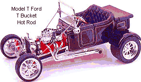
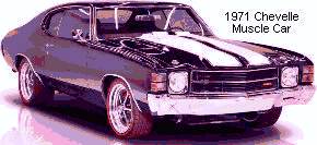

Identification of the Small Block Chevy V8 Engines -
The Small-Block Chevy (SBC) engine evolved significantly over its lifetime. Originally, the 1955-1985 engines featured a two-piece rear main seal, a driver's-side dipstick, and an oil pan with a thin front seal. By 1986, GM transitioned to a one-piece rear main seal with a passenger-side oil dipstick and block-mounted starter for manual transmissions.
The Rear Main Seal Evolution:
- Two-Piece Rear Main Seal (1955-1985): From the inception of the SBC, General Motors utilized a two-piece rear main seal. This seal was split down the middle of the crankshaft centerline. Half of the seal sat on a ridge in the engine block, and the other half resided on a ridge in the rear main bearing cap. While this design is reliable, it is prone to minor leaks, particularly at the parting lines. Mechanics generally offset these seals slightly during installation to combat oil seeping.
- One-Piece Rear Main Seal (1986-Present): In 1986, GM revolutionized the SBC by switching to a one-piece rear main seal. This design relies on a 360º rubber or synthetic lip seal that wraps completely around the crankshaft flange. To accommodate this, the block's rear crankshaft flange was enlarged, and an aluminum seal retainer/adapter plate was bolted to the back of the block. This design yields fewer oil leaks and eliminated the need to offset the seal. And due to the absence of a counterweight on the outside flange, the flywheel on these engines had to have a weight welded to it to maintain crankshaft balance.
The Oil Dipstick Evolution. The location of the SBC dipstick serves as a quick visual indicator of the engine's era and rear main seal design:
- Driver's Side (1955-1979): Early SBCs featured the dipstick tube installed on the driver's side of the engine block. These engines exclusively used the two-piece rear main seal and were typically paired with a "thin" front oil pan seal.
- Passenger's Side (1980-1985): In order to make the specific exhaust manifolds bigger to flow more air, GM moved the dipstick to the passenger side of the block, but initially retained the two-piece rear main seal design. Later variations of these pans used a "thick" oil pan gasket.
- Passenger's Side (1986-Present): When GM transitioned to the one-piece rear main seal, the dipstick remained on the passenger side. However, the newer 1986+ blocks require specific, matching one-piece oil pans because the seal and flange dimensions differ from the previous versions.
The year of manufacture of virtually every vehicle is embossed on the front, rear and side marker light lenses. But only if the original lenses are on the vehicle.
The old school Chevy V8 carbureted "smog" engines can be very powerful when certain deletions and simple modifications are made. These engines became notorious during the EPA-regulated smog era. Anyway, the best way to get more power is...
|
|
 Install
a low resistance bronze rotor distributor bushing from Speedway Motors (part
# 122222DUI) or MSD (part # 8412) for a stronger spark.
Doing all of the above will turn the engine into a screamer! I proved this many times with my customer's engines. It may have ran like a dream before, but with these modifications, it'll run beyond your wildest dreams!
A ported vacuum advance is an EPA required emissions thing. Not recommended because the engine will idle poorly, especially with an automatic transmission when in gear. Full manifold vacuum works much better. The engine will idle better and provide more power with better fuel economy.
At idle, the timing should be fully advanced by the vacuum advance canister at all times. This is why it's recommended that the vacuum hose be disconnected from the vacuum advance and plugged before setting the initial timing with a timing light. Then with the hose reconnected, as soon as the engine revs up, vacuum will drop, and the mechanical timing weights (with lightweight springs) in the distributor will take over, maintaining full timing advance so the engine will continue to produce full power.
Remove the Valve from The Heat Riser for Better Engine Performance -
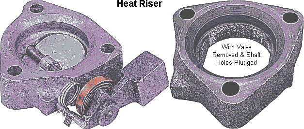 A heat riser is an automotive
exhaust component or valve designed to direct hot exhaust gases through the
intake manifold to speed up engine warm-up during cold weather.
How It Works:
- Trap Door / Valve: A spring-loaded butterfly valve or trap door inside the exhaust manifold stays closed when the engine is cold.
- Redirecting Exhaust Gases: By restricting the exhaust path, it forces hot exhaust gases to flow through a crossover passage in the intake manifold, beneath the carburetor.
- Atomizing Fuel: The localized exhaust heat warms the area beneath the carburetor or throttle body, helping liquid fuel atomize faster to improve cold-start driveability.
- Opening Up: As the engine and coolant reach operating temperature (around 180°F), the spring or thermostatic coil weakens or a vacuum canister acts on the valve, allowing it to rotate open and allow exhaust flow normally.
Common Issues:
- Sticking or Seizing: The shaft and counterweight often rust or bind with carbon over time, causing the valve to stick either open or closed.
- Carbon Clog: The internal passages of the crossover passage in the intake manifold can fill with carbon deposits, making the heating effect useless.
Deletion and Solution:
- Improve Performance (Option 1): The valve and shaft/counterweight can be removed, and to prevent an exhaust leak, the shaft holes will need to be either welded up or plugged with bolts and nuts.
- Performance Spacers (Option 2): Many vintage vehicle owners (such as classic small-block Chevrolet engine builders) replace a worn factory heat riser with an open Exhaust Heat Riser Spacer to improve exhaust flow.
Nostalgic Memorabilia -

 I remember during the 1970s-early
'80s when gas was cheap and life was fun, long before the Internet, a lot
of young people would street race their hot rods on the main drag in town.
When at an intersection with a red light, another hot rodder would pull up
next to your car, look it over front to end, then look at you, and then he'd
turn his head straight ahead, and shook his head up and down, indicating
to you: "Let's Go!" And the race was on as soon as the light turned green.
Ahhh, the good ole days.

Back in the day (early 1980s and earlier), gasoline at most filling service gas stations for various [automotive and other types of] engines were for the following compression ratios:
- For an engine with a compression ratio up to 9.3:1, it's safe to use low octane Regular gasoline. Regular/Unleaded gasoline in the United States typically has an octane rating of 87.
- If the compression ratio is between 9.3:1-10.50:1, the engine requires Premium gasoline (mid octane), which was also known as High Test in various locations. Premium gasoline typically has an octane rating of 91 to 94, depending on the region and the specific station.
- And for compression ratios above 10.50:1, the engine required Ethyl gasoline (high octane). Nowadays, due to the lead content in Ethyl, it's been replaced with Premium Unleaded, which was also known as Super Unleaded in various locations.
- 87 octane gas works great for most automotive engines with a 9.3:1 compression ratio or less. Anything above this requires premium gas, unless the [modern] engine has a knock sensor.
Actually, ALL gasoline in the early days contained lead
(Tetraethyllead)
to boost octane and protect soft cast iron valve seats from wearing.
I'd also like to share this old gas station joke: Car owner that
just pulled up to the pump at a
full service gas station says to the
gas station attendant: "Fill 'er up... Ethyl!" Gas station
attendant: "I'll fill up your car, but don't call me Ethel."


 FYI - Until the
late 1960s, certain Chevrolet small block
muscle car engines had a compression ratio as high as 11.25:1,
and a certain Chevrolet 427 big block muscle car engine had a compression
ratio of 14:1! (That was the good ol' days of hot rodding!) In fact, back
then, Chevrolet made the only naturally aspirated engine out of the top three
American (GM, Ford and MOPAR) car manufacturers that had the highest compression
ratio.
Muscle cars, raised white lettering on 70s, 60s or 50s rear tires, air shocks, glasspack mufflers, Cragar SS's or SST's, 4 barrel carburetors and low-priced gas. Cruising and racing the main drag in town with friends and associates on the weekends. Dang, the good ole days! These were the best of times, and we didn't even know it. Nowadays, it's only car show events.
Gasoline octane ratings have evolved from simple, low-octane fuels in the early 1900s to today's standardized three-grade system. Octane measures a fuel's ability to resist engine knock or premature detonation.
- Early 20th Century (1900s-1920s) Unrefined Beginnings: Early automotive fuels had very low and unmeasured octane numbers, frequently causing severe engine knock.
- The Tetraethyl Lead Breakthrough: In 1921, researchers discovered that adding lead to fuel raised the anti-knock quality cheaply.
- First High-Octane Blend: In 1926, Sinclair Oil introduced an early premium motor fuel rated at 72 octane.
- The 1930s-1950s Scale Creation: The modern octane scale was established in the 1930s using isooctane (100 rating) and n-heptane (0 rating) reference mixtures.
- Higher Compression: As post-war automotive car engines grew more powerful and featured higher compression ratios, refineries increased lead additives to push consumer fuel octane higher.
- The 1960s-1970s (The Peak of Leaded Fuel) High Numbers: Premium fuels in the 1960s were often advertised around 100 Research Octane Number (RON). Due to testing differences, a 100 RON rating from that era equals roughly 95 octane on today's modern U.S. scale.
- The Phase-Out: The U.S. Environmental Protection Agency (EPA) began phasing out leaded gasoline in the mid-1970s due to health risks, forcing a shift to unleaded formulations.
-
Modern Era (1980s-Present Date) Standardized Grading: Retail gas stations
in the U.S. adopted the Anti-Knock Index (AKI), the average of RON, and Motor
Octane Number (MON), resulting in today's typical three-tier pump standard:
- Regular: 87 octane.
- Mid-grade / Plus: 89 octane.
- Premium: 91 to 93 octane (depending on region and elevation).

 I found that when welding a nut to a broken-off bolt to extract
the stud, it's better to use a shallow jam nut instead of an ordinary deep
nut. Because the bead of weld will be more secure to the stud with a jam
nut than with an ordinary nut. This makes the weld stronger, and hopefully,
the broken off bolt can be easily removed.
Sometimes using just one air filter on a hort rod is restrictive for the amount of air the engine requires. Therefore, many ho rodders stack two air filters, one stacked on top of other, to increase the air flow. Then a longer threaded stud will need to be used.
Advertisement: Wing nuts, Pleated Air Filters and Reticulated Foam Wraps/Pre-Filters -
| Click here to contact A-1 Miller's Performance Enterprises to place an order, send your parts for repairing, and/or for FREE professional and honest technical customer service assistance and support and payment options. Please contact A-1 Miller's if you need a part or parts, or service(s) performed that's not listed or mentioned in this website. | |
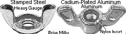 Each wingnut
listed below recommended for side-mounted air cleaner covers or battery hold-down
studs. Do not use on top-mounted air cleaner covers due to rain water seeping
into intake or when washing off engine. 1/4-20 UNC threads. Each replaces
Kohler part #'s X-276-7 and 25 100 15-S.
|
|
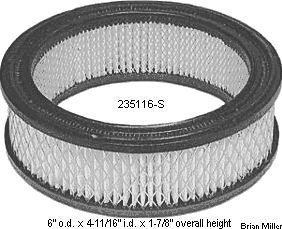 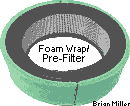 Pleated Air Filter Elements and Reticulated Foam Wraps/Pre-Filters.
Non-restricting flame retardant filter. Performance engineered for increased
breathing. Can be used with one or two 4-barrel carburetors on a mini rod
pulling vehicles, hot rods, etc., with an automotive engine. Air filter:
Kohler 235116-S; Cub Cadet 385168R2. Foam Wrap/Pre-Filter: Kohler 237421-S.
Air filter element dimensions (±): 6" O.D. x 4-11/16" I.D. x 1-7/8"
overall height.
NOTE: To clean the foam wrap/pre-filter, use brake parts cleaner, electrical/electronic contact cleaner, cleaning solvent or paint thinner (these leave behind no oily residue) and 150± P.S.I. compressed air with an air blow gun nozzle, allow to thoroughly dry, but do not add oil in an attempt to trap the dust and dirt. Oil is not recommended because some of the oil could be drawn into the paper element while the engine is running, partially clogging it. |
|
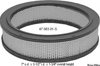 Pleated Air Filter Elements and Reticulated Foam Wraps/Pre-Filters.
Non-restricting flame retardant filter. Performance engineered for increased
breathing. Can be used with one or two 4-barrel carburetors on a mini rod
pulling vehicles, hot rods, etc., with an automotive engine. Air filter:
Kohler 47 083 01-S; Cub Cadet 117210-C1, 759-3547, 959-3547; Gravely 032494,
John Deere M83646, Lesco 012596. Foam Wrap/Pre-Filter: Kohler 52 083 01-S.
Air filter element dimensions (±): 7" O.D. x 5-1/2" I.D. x 1-3/4"
overall height.
NOTE: To clean the foam wrap/pre-filter, use brake parts cleaner, electrical/electronic contact cleaner, cleaning solvent or paint thinner (these leave behind no oily residue) and 150± P.S.I. compressed air with an air blow gun nozzle, allow to thoroughly dry, but do not add oil in an attempt to trap the dust and dirt. Oil is not recommended because some of the oil could be drawn into the paper element while the engine is running, partially clogging it. |
|
 Pleated Air Filter Elements and Reticulated Foam Wraps/Pre-Filters.
Non-restricting flame retardant filter. Performance engineered for increased
breathing. Can be used with one or two 4-barrel carburetors on a mini rod
pulling vehicles, hot rods, etc., with an automotive engine. Air filter:
Kohler 47 083 03-S; John Deere M47494 (fits JD models 200, 210, 212, 214,
216, 300, 312, 314, 316, 400); Woods 71803. Foam Wrap/Pre-Filter: Kohler
41 083 04-S. Air filter element dimensions (±): 7" O.D. x 5-1/2"
I.D. x 2-7/16" overall height.
NOTE: To clean the foam wrap/pre-filter, use brake parts cleaner, electrical/electronic contact cleaner, cleaning solvent or paint thinner (these leave behind no oily residue) and 150± P.S.I. compressed air with an air blow gun nozzle, allow to thoroughly dry, but do not add oil in an attempt to trap the dust and dirt. Oil is not recommended because some of the oil could be drawn into the paper element while the engine is running, partially clogging it. |
|
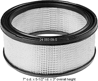 Pleated Air Filter Elements and Reticulated Foam Wraps/Pre-Filters.
Non-restricting flame retardant filter. Performance engineered for increased
breathing. Can be used with one or two 4-barrel carburetors on a mini rod
pulling vehicles, hot rods, etc., with an automotive engine. Air filter:
Kohler 24 083 09-S; John Deere GY20576. Foam Wrap/Pre-Filter: Kohler 24 083
02-S. Air filter element dimensions (±): 7" O.D. x 5-1/2" I.D. x
3" overall height.
NOTE: To clean the foam wrap/pre-filter, use brake parts cleaner, electrical/electronic contact cleaner, cleaning solvent or paint thinner (these leave behind no oily residue) and 150± P.S.I. compressed air with an air blow gun nozzle, allow to thoroughly dry, but do not add oil in an attempt to trap the dust and dirt. Oil is not recommended because some of the oil could be drawn into the paper element while the engine is running, partially clogging it. |
|
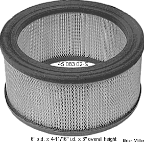 Pleated Air Filter Elements and Reticulated Foam Wraps/Pre-Filters.
Non-restricting flame retardant filter. Performance engineered for increased
breathing. Can be used with one or two 4-barrel carburetors on a mini rod
pulling vehicles, hot rods, etc., with an automotive engine. Air filter:
Kohler 45 083 02-S; Cub Cadet 759-3359. Foam Wrap/Pre-Filter: Kohler 45 083
01-S. Air filter element dimensions (±): 6" O.D. x 4-11/16" I.D.
x 3" overall height.
NOTE: To clean the foam wrap/pre-filter, use brake parts cleaner, electrical/electronic contact cleaner, cleaning solvent or paint thinner (these leave behind no oily residue) and 150± P.S.I. compressed air with an air blow gun nozzle, allow to thoroughly dry, but do not add oil in an attempt to trap the dust and dirt. Oil is not recommended because some of the oil could be drawn into the paper element while the engine is running, partially clogging it. |
|
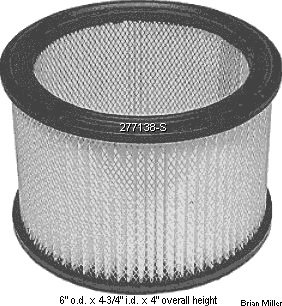 Pleated Air Filter Elements and Reticulated Foam Wraps/Pre-Filters.
Non-restricting flame retardant filter. Performance engineered for increased
breathing. Can be used with one or two 4-barrel carburetors on a mini rod
pulling vehicles, hot rods, etc., with an automotive engine. Air filter:
Kohler 277138-S. Foam Wrap/Pre-Filter: Kohler 277593-S. Air filter element
dimensions (±): 6" O.D. x 4-3/4" I.D. x 4" overall height.
NOTE: To clean the foam wrap/pre-filter, use brake parts cleaner, electrical/electronic contact cleaner, cleaning solvent or paint thinner (these leave behind no oily residue) and 150± P.S.I. compressed air with an air blow gun nozzle, allow to thoroughly dry, but do not add oil in an attempt to trap the dust and dirt. Oil is not recommended because some of the oil could be drawn into the paper element while the engine is running, partially clogging it. |
1" and 2" Carburetor Spacers for Old School Automotive V8 Engines -
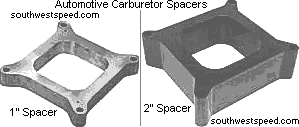 On most old school automotive
V8 engines with a 4-barrel carburetor and stock intake manifold, a 1" carburetor
spacer generally boosts torque and top-end power while avoiding low-end losses.
A 2" spacer requires specific race cams and higher RPM ranges to see gains,
and can actually lose mid-range torque on a street engine due to excessive
plenum volume.
How They Work:
- Plenum Volume: Spacers effectively extend the intake runners and enlarge the intake plenum. Taller spacers (2") provide maximum time for the fuel to vaporize, which is highly beneficial in race engines running at high RPMs.
- Throttle Response and Torque: A 1" spacer (especially a 4-hole design) increases air velocity and helps straighten the air/fuel mixture right beneath the carburetor, maximizing usable torque across the streetable RPM range (2,000-5,000 RPM).
- Heat Isolation: Spacers made of phenolic plastic or wood significantly reduce heat transfer from the hot intake manifold to the carburetor, keeping the fuel cooler and denser.
- Atomization means the breakup of liquid into fine particles, while vaporization means a transition from the liquid phase to vapor.
Key Differences at a Glance:
1" Spacer
|
2" Spacer
|
Which One Should You Choose?
- Go with a 1" spacer if you have a street-driven SBC. It offers the best bang-for-the-buck. For a dual-plane intake manifold, an open 1" spacer or a 4-hole 1" spacer usually picks up 5-10 HP and improved fuel distribution.
- Go with a 2" spacer if the engine spends its life at the track (6,000+ RPM) and you have a large single-plane intake. On a standard street engine, a 2" spacer can create "lazy" air speed and cause a noticeable loss in low-end power.
Carburetor Spacer vs Dual-Plane Intake Manifold vs High-Rise Intake Manifold -
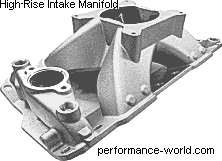
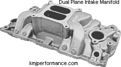 Carburetor spacers, dual-plane intake manifolds, and high-rise
intake manifolds all alter the volume, velocity, and delivery path of the
air-fuel mixture to an automotive engine. The best choice depends entirely
on the engine's operating RPM, intended use (street vs. track), and under-hood
clearance.
Carburetor Spacer:
- A carburetor spacer is a smaller, targeted bolt-on addition used to fine-tune an existing setup by tweaking plenum volume, throttle response, and fuel temperature. A high-rise intake manifold is a fundamental engine component designed to alter engine power delivery across a wide RPM band.
- A carburetor spacer acts as a tuning and heat-isolation tool positioned between the carburetor and the intake manifold.
- Function: Adds plenum volume and physically raises the carburetor to isolate it from engine heat (preventing heat soak).
- Four-Hole Spacers: Maintain the division of the manifold. They increase mixture velocity, significantly boosting bottom-end torque and low-RPM throttle response.
- Open Spacers: Combine the two sides of the plenum. They mimic a single-plane intake, trading off low-end torque for improved mid-to-top-end horsepower. Best for fine-tuning an existing setup.
Dual-Plane Intake Manifold:
- A dual-plane intake manifold has a split plenum chamber just below the carburetor. One plane (runner) feeds four cylinders, and the second plane feeds the other four.
- Function: Maintains high intake velocity at lower engine speeds by treating the carburetor as two smaller, separate 2 barrel carburetors.
- Performance Characteristics: Provides excellent idle quality, strong low-end torque, and superior throttle response. It limits the maximum peak horsepower but provides a broader, more usable power band (usually from off-idle to 5,500/6,000 RPM).
- Best For: Daily-driven street cars, mild street-strip cars, towing, and applications with a manual transmission or lower rear-end gear ratios.
High-Rise Intake Manifold:
- A high-rise intake manifold is a taller, more aggressive variation that can feature either a single-plane or dual-plane design.
- Function: Because of the taller design, the intake runners are longer and straighter. This reduces sharp turns and allows for a massive influx of air.
- Performance Characteristics: The taller design fundamentally increases plenum volume and runner length. This is excellent for mid- to high-RPM power and torque, making engines breathe far better at higher revs (typically 2,500 RPM and up).
- Best For: High-performance street/strip applications, dedicated race cars, or engines running high-lift camshafts. Note: The extra height often requires a cowl induction or aftermarket raised hood for clearance.
How to Choose:
- Use a Carburetor Spacer to fine-tune an existing dual-plane or single-plane setup, or to cure fuel-boiling issues from engine heat soak.
- Choose a Dual-Plane if you want a great idle and excellent low-RPM torque for street cruising.
- Choose a High-Rise if you are building a high-RPM race or performance street engine and have the hood clearance.
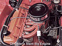 FYI - The automotive V8 high
rise intake manifold and Chrysler's Slant Six engine (with the longer intake
manifold runners) were designed to atomize the fuel better so the engine
will produce more power at higher RPM and get better fuel mileage at any
RPM. If anyone tells you differently about the Chrysler slant six engine,
then they are wrong! These are the ONLY reasons Chrysler made the slant six
engine, designed it the way they did and it works!
Exhaust Manifold or Header Pipe Mounting Gaskets VS Using Just Silicone Sealant Alone - Which Works Best?
Personally, whenever we install exhaust manifolds or header pipes on an engine, we don't use gaskets. Instead, we use RTV clear silicone sealant because silicone will not burn due to normal or extreme exhaust heat. (Silicone can withstand up to 5,000º F.) Anyway, gaskets always compress or "squeeze down" where the fastening bolts are, causing the cast iron manifold to flex a few thousandths of an inch or thinner steel header flanges to bend more than a few thousandths of an inch where the mounting bolts are. When metal is compressed, the uncompressed area that's between the bolts will allow the gasket(s) to leak and eventually burn out. Also, before we install the manifolds or headers on an engine, we use a long, wide flat file to make sure the mounting flanges on the manifolds or headers are perfectly flat. Using silicone and the elimination of gaskets will allow the manifolds or header flanges to be mounted flat against the cylinder heads, creating absolute metal-to-metal contact, which also keep the mounting bolts securely tight. The bolts will not loosen under any circumstances. Plus, the silicone fills in the imperfections between the two metals, eliminating any leaks. By the way - it's best to use Clear RTV Silicone Adhesive Sealant for three reasons: Gaskets don't always seal the irregularities between mating metals, especially thin metal covers; being it's an adhesive, it bonds parts together, forming a leak-proof seal; and being it's clear, it makes for a clean and professional-looking repair job. When applied sparingly, it can't be easily seen or noticed between the parts. Also, engine heat has very little effect on silicone rubber. It can withstand up to 2,500 degrees heat.
On a small-block Chevy V8, to provide more lubrication to the timing chain and sprockets, drill a 1/32" or 3/64" hole through one of the front lifter oil galley plugs, which are located directly behind the upper timing sprocket or gear.
Crucial Details and Best Practices:
- Which Plugs: The front of an SBC block features three oil galley plugs. The center/upper plug aligns with the camshaft bearings, while the two outboard (left and right) plugs block the main lifter oil galleys or oil passageways.
- Depending on the oil pump pressure rating, drill just one plug or both plugs to spray pressurized oil directly onto the back of the timing chain and upper sprocket.
- Hole Size Warning: Most professional engine builders strongly recommend using a 1/32" or 3/64" (0.030" or 0.040") orifice.
- Alternative Benefit: Aside from lubricating high-performance timing sets or gear drives, these tiny holes also serve to bleed trapped air out of the lifter galleys upon a cold start, preventing initial lifter ticking.
- IMPORTANT! Always remove the plug(s) from the engine block before drilling it/them. Do not drill either of them while they're still installed in the block. Metal cuttings will dislodge directly into the oil galley(s) and destroy the bearings upon startup.
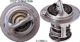 If the engine's thermostat
doesn't already have this, drill a 3/32" hole through the thermostat plate
area. This will allow any air that's trapped in the block to be pushed out,
and it'll allow coolant to drain into the block to prevent air pockets, which
could result in premature overheating. By drilling the 3/32" hole, this will
allow any air out of the block, especially when filling the radiator/engine
with coolant, and this hole will also help the engine warm up faster by allowing
the coolant make contact with the coil spring in the thermostat.
The reason the blades on automotive radiator fans are offset is to reduce the "chopping" sound at higher rpms. Otherwise, they'd sound like an airplane going down the road.
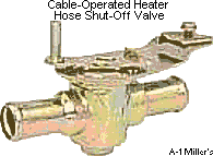 The outlet/hot side heater
hose is most likely to burst close to the engine block or water pump because
this is the hottest point. To prevent this from happening, replace the OEM
1 ply heater hose with a heavy duty 2 ply reinforced hose and avoid any sharp
bends to prevent from having a blow-out later. Because sharp bends weakens
the hose material by placing stress on the hose. Also, install a cable-operated
shut-off valve in the outlet hose that can be operated from inside the vehicle.
The shut-off valve saves wear and tear on the heater hoses and heater core
during warm weather and allows the a/c to produce colder air.
I think most older vehicles don't need to be converted to disc brakes. Because drum brakes will work just fine as long as they're in good condition. The only exception is when replacement drum brakes and/or parts are not available. Besides, brakes only work as good as the person who use them.
Ignition points should never be cleaned with sandpaper or emery cloth. Doing this will leave grit between the contacts, which will cause a poor connection. Instead, a thin, steel points file should always be used. This tool will leave the contacts clean for a good connection.
When regrinding a valve face, always true-up the end of the valve stem. Because in an OHV cylinder head, a rounded or unevenly worn valve stem tip can cause the rocker arm to slip, slide sideways, or track improperly.
Why It Happens:
- Loss of a Flat Contact Patch: A new valve stem tip is square, flat, and perpendicular to the valve stem. This gives the end of the rocker arm a stable, centered surface to push against.
- The "Ramp" Effect: When the tip becomes rounded or "peened over" on one side, it creates a sloped or spherical surface. As the rocker arm applies heavy downward pressure, the rounded surface acts like a ramp, forcing the rocker tip to push or slide toward the lower/worn side.
- Side-Load Forces: Valve trains naturally experience some side-to-side sweeping motion, but a deformed valve tip exaggerates this, causing roller tips to ride on the edge or stamped steel tips to slip off-center. This accelerates wear on both the rocker and the valve guide.
What Else to Check. If a rocker arm is slipping to one side, a rounded valve tip might be a symptom or a contributing factor, but look for these related root causes:
- Improper Pushrod Geometry: Incorrect pushrod length can cause the rocker tip to sweep too far across the valve face, leading to side-loading and abnormal tip wear.
- Misaligned Guide Plates: If aftermarket guide plates are being used (common with screw-in studs), a misaligned or worn plate can cock the rocker arm at an angle relative to the valve stem.
- Worn Rocker Trunnions or Balls: Slop in the fulcrum pivot allows the entire rocker body to wander side-to-side.
How to get more power out of an old school Chevy V6 or small block Chevy V8 smog engine...
-
 Remove all the smog crap and
smog-related sensors from the engine.
- Connect the vacuum advance canister to a full manifold vacuum port. This is located below the throttle plates on the carburetor or on the intake manifold.
- Install lightweight springs for the mechanical advance in the distributor. Be sure to clean and lubricate the center reciprocating part and flyweights, too.
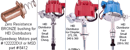
- Replace the low quality and high resistance OEM or aftermarket carbon bushing in the center of the HEI distributor cap, which can melt the cap and cause a misfire, with a zero resistance BRONZE bushing (Speedway Motors part # 122222DUI or MSD part # 8412). This part provides a stronger spark and does not get hot whatsoever.
- Install dome pistons in the engine.
-
Doing all of the above should turn the engine into a screamer.
Small Block Chevy (SBC) Distributor Gear Alignment Details -
-
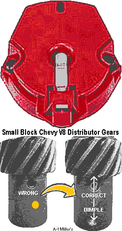 The Dimple Mark: OEM factory
GM and most aftermarket distributor gears feature a small drilled dimple
or paint dot right next to the roll pin hole on one side of the gear.
- On a Small Block Chevy (SBC) distributor, the dimple or dot at the bottom of the drive gear should be in alignment with the exact same direction as the firing tip of the rotor.
- Rotor Phasing: Aligning the dimple in alignment with between two gear teeth and with the leading edge of the rotor tip ensures the gear is indexed correctly on the shaft.
- 180° Reversal Option: The gear can be rotated 180 degrees if there's clearance issues. Turning the gear completely around changes the rotational clocking of the distributor housing by about 12 to 14 degrees. Usually, with the timing set correctly, the vacuum advance canister is at the 7:30 position, and with the gear reversed 180º, this puts it at around the 8:00 position. This helps position the vacuum advance canister so it clears the intake manifold or firewall.
I always rebuild OEM GM HEI distributors. I disassemble, clean, lubricate the shaft, and drill 2 holes through the housing so the bushings will receive crankcase oil. Then I replace the OEM carbon bushing with a new MSD bronze bushing in the center of the distributor cap for a stronger spark and to prevent from melting the cap. i also install lightweight springs for the mechanical advance so the engine will produce more power. The springs in an old sbc points distributor will fit the HEI distributor. They're lightweight, too.
What's the Difference Between the Small Block Chevy 305 and 350 Distributor Vacuum Advance?
Understanding Vacuum Advance and Why It's Needed: While Small Block Chevy (SBC) 305 and 350 distributors are often physically interchangeable, their vacuum advance units typically differ in calibration to match distinct engine characteristics, such as compression ratios and timing requirements. A 305 vacuum advance is often tuned for higher emissions-era vacuum signals, whereas a 350 vacuum advance is tuned for higher performance and broader timing curves.
Key Differences and Considerations:
- Calibration Differences: Vacuum advance units differ in the amount of vacuum needed to start advancing and the total degrees of advance provided. The 305, having smaller bores, often require a different advance curve to optimize combustion compared to the 350.
- Physical Interchangeability: The 305 distributor (specifically 1984-style) can physically fit into a 350 (e.g., 1992), but they may cause timing inconsistencies if the advance curve doesn't match the new engine's needs.
- Ported vs. Manifold Vacuum: Regardless of engine size (305 or 350), the advance unit operates based on the vacuum source (ported vs. manifold), which dictates whether timing advance occurs at idle or during acceleration.
- Usage Examples: Using a 305 distributor on a 350 might lead to early or excessive vacuum timing advance, causing detonation/pinging sound due to the 350's higher performance demands. On the otherhand, using a 350 distributor on a 305 might make it run sluggish if the vacuum unit requires higher vacuum levels to operate than the 305 produces.
- For optimal performance, it is recommended to use a vacuum advance unit designed specifically for a 305 or 350 engine, especially during carburetor conversions.
Connecting the vacuum advance to the [part time] throttle vacuum (often called "ported" or "timed" vacuum) is to dynamically adjust ignition timing based on engine load. It improves throttle response, increases fuel efficiency during cruising, and prevents the engine from overheating.
Here is a breakdown of why this connection is important:
1. The Core Purpose: Load-Based Timing
An engine requires different amounts of spark advance depending on how hard it is working (load).
At cruising speeds: The engine is under light load, taking in less air, and the fuel mixture burns relatively slowly. The vacuum advance uses the high vacuum signal to advance the timing, ensuring the fuel burns completely before the exhaust valve opens. This drastically improves fuel economy, increases engine power and lowers emissions.
At full throttle: The engine is under a heavy load and cylinder pressure spikes. The vacuum drops significantly, and the vacuum advance disengages. This prevents dangerous pre-ignition or engine "knock" (detonation).
2. The Mechanics: of Ported vs. Manifold Vacuum
There are two ways to connect the vacuum advance on a carburetor, and their purpose dictates how the car behaves:
Ported Vacuum (Throttle Body): The vacuum port is located just above the throttle plates. At idle, the throttle plates block this port, so there is no vacuum going to the vacuum advance. As the throttle slightly opens, air speeds up past the port, creating a strong vacuum signal that immediately advances the timing for a smooth transition. This was standard on many factory vehicles from the emissions era onward.
Manifold Vacuum: The port is part of the intake manifold, meaning it has high vacuum the moment the engine is running. This advances the timing at idle, which yields a smoother and stronger idle. Many performance enthusiasts and restorers prefer connecting the vacuum advance to manifold vacuum for a more efficient burn.
Summary of Benefits
- Better Drivability: Eliminates engine stumbling or hesitation when you press the gas pedal.
- Increased MPG: Optimizes the timing at part-throttle cruising so you get better gas mileage.
- Extended Engine Life: Ensures complete combustion of fuel, keeping raw fuel from washing oil off the cylinder walls.
- Cooler Running: Idling or cruising with properly advanced timing prevents the engine from running too hot.
Connecting the vacuum advance to a full-time manifold vacuum port ensures the ignition timing stays stable at idle , while still providing extra advance during part-throttle acceleration for better fuel economy and drivability.
The main functional differences and advantages of using ported vacuum depend on how you drive and tune the engine.
The Core Advantage: Idle Stability
No Timing at Idle: Ported vacuum is taken from above the throttle plates, meaning there is virtually no vacuum signal when your foot is off the gas.
Stable Base Timing: By preventing vacuum advance at idle, the engine relies solely on its base (initial) timing. This prevents erratic idle surges, especially on older engines or vehicles with aggressive, long duration camshafts that already have low, unstable manifold vacuum.
Part-Throttle Performance and Economy
Timing on Demand: As soon as you step on the throttle and open the plates, the vacuum port is exposed to the engine's vacuum, pulling timing in.
Efficiency: This extra timing advance at light-load cruising (when the throttle is just barely cracked) allows for a more complete fuel burn. This translates to crisper throttle response and better gas mileage.
Ported vs. Manifold Vacuum
While ported vacuum is the standard for street-driven carbureted and older vehicles, understanding the trade-off with manifold vacuum can help you tune your specific setup:
Ported Vacuum Manifold Vacuum
- Vacuum Source Located above the throttle plates. Located below the throttle plates (gets intake vacuum).
- Timing at Idle None (timing relies only on base mechanical settings). High (adds 10-15 degrees of advance, which boosts idle speed and cooling).
- Pros Smoother idle on modified engines, less prone to run-on/dieseling when shutting the engine off. Cooler idling temperatures, creates better low-end torque.
- Cons Less cooling at idle; slightly less low-end power. Can cause rough, surging idle on engines with large camshafts (high overlap).
Tuning and Best Practices
If you are deciding which to use, always check the distributor's technical specifications, as most aftermarket units (such as those from MSD or Summit Racing) are specifically engineered to run on ported vacuum. To avoid engine hesitation or pinging under acceleration, you can utilize an adjustable vacuum advance canister to dial-in exactly how much timing the engine has at part throttle.
Additionally, the 305's distributor originally comes with very stiff mechanical flyweight advance springs that allow full timing advance at around 4,000 RPM. The 350's distributor originally comes with weaker mechanical flyweight advance springs that allow full timing advance at around 2.500 RPM. So in order for the 305 to produce more power at lower RPMs, install the weaker springs designed for the 350.
When using a Chevy 305 engine with its original distributor, to make it produce lots more power, replace the stiff mechanical timing advance springs in the distributor with lightweight springs out of a 283, 307, 327, 350 or 400 distributor. The 305's stiff springs fully advances the total timing of 36° BTDC at around 4,000 RPM, and the other SBC engine's lightweight springs fully advance the total timing of 36° BTDC at around 2,500 RPM. I did this with several stock 305s, and this simple, easy trick made a world of difference in the increase of power. Also, at idle, the timing should be fully advanced by the vacuum advance canister at all times. This is why it's recommended that the vacuum hose be disconnected from the vacuum advance before setting the initial timing with a timing light. With the hose reconnected, as soon as the engine revs up, vacuum will drop, and the mechanical timing weights (with lightweight springs) will take over, maintaining full timing advance.
Installing light-weight mechanical advance springs and a properly adjusted vacuum advance canister (like those often used in performance-tuned 350 setups) will likely make a 305 Small Block Chevy (SBC) feel more responsive and produce better part-throttle power and efficiency, though it may not increase peak horsepower. Stock 305 distributors were often set up conservatively for emissions and fuel economy, with heavy mechanical advance springs that allow the timing to advance slowly.
Here is how these changes affect performance:
- Lighter Mechanical Advance Springs: These allow the timing to "come in" sooner (lower RPM), improving throttle response and acceleration.
- Without changing the weights, bringing all the timing in by roughly 2,800-3,000 RPM is generally optimal.
- Vacuum Advance: This adds timing under idle and light-load conditions (like cruising), preventing "lazy" throttle response and increasing fuel efficiency. It does not add power at wide-open throttle (WOT) because vacuum drops to near zero, but it significantly helps drivability.
- For better performance, connect the vacuum advance to manifold vacuum (port below the throttle plates for full vacuum at idle) rather than ported vacuum (even with the throttle plates).
For a typical Small Block Chevy (SBC) V8 (e.g., 350), and depending on the compression ratio, set initial timing at 8-12° Before Top Dead Center (BTDC) at idle and total advance to 34-36° at 2,500-3,000 RPM (with vacuum advance disconnected). Optimal timing varies based on cam, cylinder head design, and fuel, with performance engines often preferring higher initial timing.
Key Timing Specifications:
- Initial Timing (Idle): Generally 8-10 degrees BTDC for stock engines, and up to 12-15 degrees BTDC for engines with performance camshafts.
- Total Timing: Aim for 34-36 degrees BTDC total (mechanical + initial) reached by 2,500-3,000 RPM.
- Vacuum Advance: Connect to ported vacuum for initial testing, though manifold vacuum is often used for better idle cooling.
Steps for Setting Timing
- Preparation: Bring the engine to normal operating temperature and plug the vacuum advance line.
- Initial Setup: With the engine off, check that the #1 cylinder is at 0º TDC and the distributor rotor points to the #1 spark plug wire.
- Adjust Timing: Using a timing light, loosen the distributor hold-down clamp. Rotate the distributor clockwise to retard and counter-clockwise to advance the timing.
- Confirm Total: Rev the engine to 3,000± RPM and check that the total advance is around 36° BTDC.
- Distributor Type: Stock HEI distributors often prefer around 34-36° total.
- Fuel Requirements: If the engine knocks, reduce total timing by 2 degree increments.
- Mechanical Timing: If initial timing is too low (e.g., set at 0º TDC), the car will likely run sluggish.
On automotive engine distributors, lightweight springs are used in a mechanical (centrifugal) distributor advance to allow the ignition timing to advance faster at lower engine RPMs. These springs allow the centrifugal weights to swing outward sooner, reaching "total timing" (maximum advance) at a lower engine speed, which is used to improve throttle response and performance in many engines.
Key Reasons for Using Lightweight Springs:
- Faster Timing Curve: Lightweight springs offer less resistance to the centrifugal weights, allowing the advance mechanism to engage at a lower RPM.Faster Throttle Response: By bringing the total timing in earlier (e.g., all-in by 2,500–3,000 RPM rather than 4,000+), the engine reaches its peak efficiency range quicker.Performance Optimization: In many applications, particularly performance-oriented engines, an early, quick advance curve creates better acceleration, whereas heavy springs slow down this process.
- Adjustability: Mechanics change to lighter springs as part of a "distributor curve kit" to customize the engine's behavior, allowing for a faster or slower, more linear, or more aggressive advance rate to avoid spark knock.Conversely, using springs that are too light can cause the timing to come in too quickly, leading to detonation (pinging sound) or an unstable idle.
Medium springs are used in mechanical timing advance mechanisms to control the rate of spark advance, ensuring it matches the engine's RPM without advancing too quickly, which can cause spark knock or "pinging sound". They act as a middle ground between light springs (fast advance) and heavy springs (slow advance), offering a tailored, progressive advance curve.Key Reasons for Using Medium Springs:
Preventing Premature Advance: Lighter springs can cause the timing to advance too early (e.g., at 800 RPM or lower), leading to engine misfire or detonation. Medium springs hold the weights back until a higher, more appropriate RPM.Creating a Progressive Curve: Often combined with a lighter spring, medium springs allow the timing to start advancing quickly but slow down the rate of advance at higher RPMs, reaching "total timing" at the desired engine speed, typically around 3,000 RPM.
Stability at Idle: They ensure the mechanical advance does not activate during idle or low-speed operation, providing better timing stability and preventing an unsteady idle.Balancing Performance: They provide a balanced approach, allowing for quicker advance than heavy springs for performance, without the risks associated with excessively fast "light spring" curves.
Heavy springs in a mechanical timing advance system (centrifugal advance) are used to slow down the rate of advance, delaying when the maximum ignition advance is achieved until higher RPMs. Stiffer springs fight the centrifugal force of the distributor weights more effectively, preventing premature timing advance that can cause engine detonation or "pinging sound".
Key Reasons for Using Heavy Springs:
Delay Timing Curve: They prevent the mechanical advance from starting too early, often used to keep initial timing stable at idle.
Prevent Detonation: By preventing the timing from advancing too quickly, they protect the engine from pre-ignition/detonation, particularly under high loads.Tailor the Timing Curve: Heavier springs (or a combination of one light/one heavy) are used in "slower" tuning kits to ensure total timing occurs at higher RPMs (e.g., 3,000+ RPM) rather than too early (e.g., 1,500 RPM).Distributor Stability: Stiffer springs prevent "flutter" of the advance weights, resulting in more stable timing.In summary, light springs allow for fast advancement (suitable for racing), while heavy springs restrict that motion for a slower, controlled advance (better for street tuning).
Many high-performance automotive engine builders often weld the mechanical advance weights in place and they install a solid plate in place of the vacuum advance canister, so the ignition timing is in a "fixed" position, ensuring the total timing remains the same rather than automatically advancing with RPM. This technique is common in high-performance engines to prevent detonation and provide a consistent ignition curve.
Small-block Chevy (SBC) V8s with stock camshafts should idle at their initial/base timing setting with the vacuum advance disconnected. While full manifold vacuum is often used for cooling and idle quality, the advance canister must be disconnected and plugged while setting the base idle speed and timing.
Why the distinction matters:
- Base/Initial Setting: The mechanical baseline (usually 6° to 12° Before Top Dead Center depending on the SBC) provides the safest, most stable timing for the engine to start and idle.
- Full Vacuum Advance: When connected to full manifold vacuum, the vacuum canister adds an extra ~10° to 15° of timing at idle. This can boost idle RPM and keep the engine cooler, but it artificially masks the true base timing, making the engine prone to hard starts, kickback, or detonation if not set up correctly.
Idle Timing by Transmission Type.:
- For both automatic (A/T) and manual transmissions, the process for establishing a correct idle involves base settings, not total vacuum advance.
Automatic Transmission:
The Challenge: Engines with A/Ts idle under "load" when the transmission is in gear, which drops engine vacuum and RPMs.
- Procedure: Set the base idle and initial timing with the vacuum advance disconnected and the transmission in Park or Neutral. Once the base timing is dialed in and the vacuum hose is reconnected to a ported vacuum source (which reads zero vacuum at idle), the engine will maintain a steady idle without fluctuating when shifting into gear.
Manual Transmission:
The Challenge: Manual transmissions don't load the engine at a stop, but they require reliable, clean throttle response when engaging the clutch from a dead stop.
- Procedure: You have more flexibility here. Many builders prefer connecting the vacuum advance to full manifold vacuum to achieve a slightly higher, smoother, and cooler idle. However, this must ensure that the initial timing is set accurately with the vacuum hose temporarily plugged.
Step-by-Step Tuning Rule. Whether an A/T or manual, always follow these rules to tune the distributor:
- Disconnect and Plug: Pull the vacuum hose off the distributor advance canister and plug it with a golf tee or screw so it don't have a vacuum leak.
- Set Initial Timing: Rotate the distributor body so the timing mark aligns with the stock specifications (typically 8° to 12° BTDC).
- Set Idle Speed: Adjust the idle screw on the carburetor until it hits the target RPM (usually 600-700 RPM in gear for A/T; and 700-800 RPM for manual).Reconnect the Vacuum Advance: Reattach the vacuum hose to either a manifold or ported source, depending on the cam and heat preferences.
Setting the Ignition Timing with a Strobe Timing Light - [Return to previous paragraph, section or website]
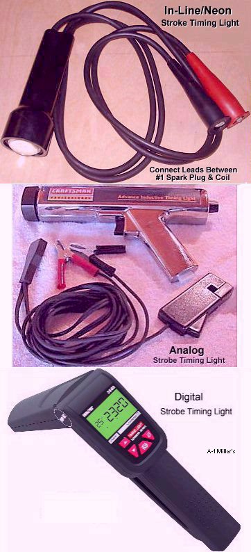 There are 3 types of strobe
timing lights, in-line/neon, analog, and digital.
In-Line/Neon Timing Light. This very old, vintage, self-powered timing lights relied solely on the electrical energy from the ignition circuit to flash.
- This type of vintage timing light requires no external power from a battery to illuminate it. Instead, it has a special, bright light bulb with a powerful magnifying glass that illuminates when the spark is made. To use this type of timing light, connect one lead to the #1 cylinder spark plug and connect the other lead to the spark plug wire, then start the engine. It's ideal for use on engines with magneto or solid state ignition.
- Key details about these early lights: How they worked: Unlike modern lights that clip onto the 12 volt battery and clamp around the #1 spark plug wire, these older units were connected directly in-line between the spark plug and the plug wire, or clamped right over the wire. The high voltage produced by the engine's ignition coil was used to power a small neon bulb inside the light, which would illuminate each time the spark plug fired.
- Drawbacks: Because they used a basic neon gas bulb rather than the bright Xenon tubes found in later tools, their flash was very dim. They were largely ineffective during the day and usually required mechanics to check the timing in a dark garage or at night. For better visibility, they must be held close to the timing mark at night or in a dark, shaded area. These are very old and are considered obsolete because they don't illuminate too well.
- Modern Equivalents: While neon types are mostly a thing of the past for automotive work, self-powered inductive versions (which run on built-in batteries rather than the car's system) are still commonly manufactured today.There are 3 types of strobe timing lights, in-line/neon, analog, and digital.
Analog vs Digital Timing Lights - (Added 6/5/26)
An analog timing light uses a mechanical dial to set advance and a simple xenon strobe to illuminate timing marks, while a digital timing light uses an LCD screen, pushbuttons, and microprocessor-controlled circuitry to display RPM, advance, and voltage readouts. To use an inductive analog timing light or digital timing light, the engine can be running while connecting the clamps on the battery posts in their respective order, then connect the inductive pickup on the #1 spark plug wire. Choosing between the two depends on your budget and how often you tune the engine.
- Analog lights rely on a knob or dial that you need to rotate on the back of the gun to manually delay the flash (the "dial-back" feature).
- How it works: You dial in the desired advance degree (20º) on the knob and aim the strobe at the timing mark or tab. When the timing mark on the flywheel lines up with the T on the flywheel, the timing is perfectly set.
- Pros: Highly affordable, very reliable, and sturdy due to fewer electronic components.
- Cons: No multi-function readouts; you have to rely on a separate tachometer to read engine RPM.
- Digital timing lights feature a built-in LCD screen that allows you to input specific engine parameters electronically via pushbuttons.
- How it works: You use the buttons to set the advance degree (20º) on the screen. Similar to analog, you adjust the points until the timing mark aligns with the T on the flywheel, while the screen verifies the exact angle.
- Pros: Highly accurate and versatile. These often display continuous engine RPM, voltage, and dwell angle in addition to timing advance.
- Cons: More expensive, and the electronic displays can be more sensitive to damage due to high-heat or high-vibration environments.
Which One Should You Choose?
- Choose an in-line/neon timing light if you are on a budget, only occasionally check base timing on an engine with magneto or solid state ignition, and prefer a simpler, long-lasting tool.
- Choose an analog adjustable light if you are on a budget, only occasionally check base timing on an engine with battery ignition, and prefer a simpler, long-lasting tool.
- Choose a digital timing light if you work on a variety of small engines, require an all-in-one diagnostic tool (tachometer/voltmeter/advance), or value the convenience of a backlit, easy-to-read screen.
When building a high compression engine and burning 87 octane gas with the usual timing, to lessen the possibility of pre-ignition, which causes detonation and pinging, chamfer and smooth the top edge and valve reliefs of each piston and smooth out the combustion chamber in the heads. I've done this many times and it works great. Giving the top sharp, square edge of pistons a beveled or chamfered smooth angle, and smoothing out the combustion chamber of a high-compression engine will lessen the chance of pre-ignition, which causes detonation and pinging.
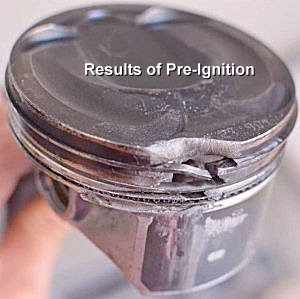
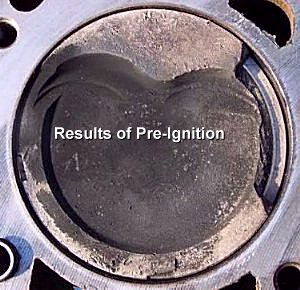
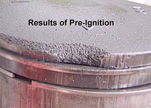 Cast iron is
more prone to pre-ignition than aluminum because it has lower thermal
conductivity and higher heat retention, which creates localized hot spots
in the combustion chamber.
Why Cast Iron Retains More Heat:
- Thermal Conductivity: Aluminum conducts heat roughly two to three times faster than cast iron, pulling thermal energy rapidly away from the combustion chamber and into the cooling system. Cast iron transfers heat much more slowly.
- Heat Soaking: Cast iron has a higher thermal mass and tends to "heat soak," holding onto high temperatures longer. This allows sharp edges, carbon deposits, or thin areas in the combustion chamber to stay glowing hot.
- Hot Spot Ignition: When parts of a cast-iron head or block stay excessively hot, those hot spots can ignite the air-fuel mixture prematurely before the spark plug fires, leading to pre-ignition or knock.
How Aluminum Solves This:
- Rapid Dissipation: Aluminum sheds heat aggressively from the combustion chambers, keeping overall chamber temperatures lower.
- Higher Compression Ratios: Because aluminum cools the charge more effectively, engineers can run higher compression ratios on standard pump gas without triggering destructive pre-ignition.
Chamfering or Radiusing the Sharp, Square Edges on Pistons and/or in Cylinder Heads Will Significantly Lessen the Chance of Pre-ignition and Detonation.
In a high-compression engine, minimizing thin protrusions is a critical safety measure because of how heat transfers within the combustion chamber. Chamfering the top edges of the pistons and smoothing out the combustion chamber significantly reduces the chances of both pre-ignition and detonation. In a high-compression engine, these modifications—often referred to as radiusing or deburring—target the primary mechanical catalysts for abnormal combustion. However, it is crucial to understand that they affect pre-ignition and detonation in two entirely different ways.
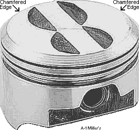 1. How it Eliminates Pre-Ignition
(Preventing Hot Spots). Pre-ignition happens when the air-fuel mixture is
ignited before the spark plug fires.
- The Problem: Sharp edges on a piston crown, casting flash in the cylinder head, or exposed threads absorb heat rapidly but cannot dissipate it quickly. Under high compression, these sharp areas act exactly like a glow plug.
- The Solution: By chamfering (radiusing) the piston edges and polishing the combustion chamber, you eliminate these microscopic thin edges. Heat is distributed evenly across a smooth, continuous aluminum surface rather than concentrating at a sharp point, neutralizing potential hot spots.
2. How it Reduces Detonation (Improving Flame Travel & Quench). Detonation occurs after the spark plug fires, when the remaining unburnt "end-gas" in the far corners of the chamber spontaneously explodes due to extreme heat and pressure.
- The Problem: Sharp ridges and rough surfaces disrupt the orderly, progressive path of the flame front. They can also cause pockets of fuel to become trapped or stagnate, making them highly susceptible to auto-igniting ahead of the flame.
- The Solution: A completely smoothed out chamber allows the flame front to travel cleanly, quickly, and uniformly outward from the spark plug. The faster and more evenly the fuel burns, the less time the unburnt end-gases have to heat up and detonate.
Why Chamfering or Radiusing Edges Prevents Pre-Ignition:
- Eliminates Hot Spots: Sharp and square edges or aggressively ridged designs on the top piston land and crown have very low thermal mass. Because they cannot dissipate heat into the rest of the thicker aluminum body quickly enough, they act like thin wires or sheet metal and heat up rapidly under hot combustion. These edges can easily begin to glow red hot, acting like a glow plug.
- Prevents Early Auto-Ignition: Pre-ignition happens when the compressed air-fuel mixture is ignited prematurely by an uncontrolled thermal source before the spark plug fires. A glowing, un-radiused edge on a piston edge and/or dome is one of the primary mechanical triggers for this catastrophic event.
- Reduces Detonation (Knock/Ping): While technically different from pre-ignition, detonation happens after the spark plug fires when extreme heat and pressure cause pockets of unburnt gas to spontaneously explode. By radiusing sharp edges (including around valve pockets and the piston crown perimeter), you reduce overall chamber temperature spikes, lessening the chance of detonation.
Where to Focus When Chamfering or Radiusing:
-
When preparing a piston, professional engine builders look for any sharp
transitions that feel crisp to the finger:
- The Piston Periphery: Sharp step or aggressive ridge above the top ring land.
- Stamped Part Numbers or Stamped Markings: Deep stamps can sometimes leave a raised, sharp burr.
How to Chamfer or Radius the Top Edge of a Piston:
- To create a precise angle on the top edge of a piston, it's best to use a large metal lathe with the piston secured in the chuck to carefully remove (machine away) the sharp 90-degree angle.
- If a large metal lathe isn't available, clamp the connecting rod with the piston in a bench vise and carefully use a large fine flat file to create an angled chamfer around the top edge of the piston. Give the chamfer about a 1/2" wide flat area at a 45º± angle.
- Maintain a consistent angle: Position the tool or file at a steady 30-to-45-degree angle against the top perimeter edge of the piston crown.
- Work evenly on the edge: Do not press too hard or remove excessive material, as you only want to create a small, uniform angle to remove the sharp edge.
- Finish the surface: Remove any burrs that could cause hot spots or detonation to create a smooth, rounded or curved edge, gently use 400 grit sandpaper or fine emery cloth.
- IMPORTANT! When smoothing the edge, take care not to alter the piston's weight significantly or touch the critical flat ring-land surfaces.
Pre-Ignition occurs more frequently and will cause more damage to the pistons in a high-compression engine when it is placed under a heavy load. Pre-ignition is a dangerous engine problem where the air and fuel mixture inside the cylinder ignites before the spark plug fires. Pre-ignition happens when a hot spot inside the combustion chamber acts like a glow plug (hot spot) and sets off the fuel too early during the compression stroke.
Common causes include:
- Glowing carbon or lead deposits on the piston or cylinder head.
- An overheated or damaged spark plug tip.
- Superheated exhaust valves.
- Low-octane fuel or incorrect oil mixing in boosted engines.
Effects and Damage:
- When the fuel ignites too early, the piston is forced to fight against the expanding gases while it is still moving upward. This creates extreme mechanical stress and high heat.
- It can burn away the top edge of a piston or burn a hole through the top of a piston within minutes.
- It can crack spark plugs or bend connecting rods.
Pre-Ignition vs. Detonation (Knock):
People often confuse pre-ignition with engine knock or detonation, but they are different:
- Pre-ignition happens before the spark plug fires.
- Detonation (Knock) happens after the spark plug fires, when remaining pockets of fuel explode from high heat and pressure. Detonation causes a "pinging" sound, while pre-ignition is often silent until catastrophic engine failure occurs.
Why Heavy Loads Increases Pre-Ignition:
- Higher temperatures: A heavy engine load (like accelerating hard or towing at low RPM) increases cylinder temperatures and pressures.
- Hot spots: These extreme temperatures can cause tiny carbon deposits, sharp edges, or an overheated spark plug tip inside the combustion chamber to glow red-hot.
- Early ignition: This glowing hot spot acts like an unauthorized spark plug, lighting the fuel-air mixture before the actual spark fires.
Pre-Ignition vs. Detonation (Knock)
- People often confuse pre-ignition with detonation (also called engine knock or pinging sound), but they are different:
- Pre-ignition: The fuel ignites too early from a hot spot before the spark plug fires, creating immense pressure while the piston is still moving up. It is silent and can melt a hole through a piston in seconds.
- Detonation (Knock): The fuel-air mixture is ignited normally by the spark plug, but the remaining unburned fuel explodes spontaneously afterward due to high heat and pressure. This makes a metallic "pinging" or knocking sound.
Engine detonation is the uncontrolled, explosive ignition of the remaining fuel-air mixture in the combustion chamber after the spark plug has fired.
What Causes Detonation?
- Low-octane fuel: Fuel that lacks sufficient resistance to high heat and pressure can self-ignite.
- Over-advanced ignition timing: Spark plugs firing too early cause excessive pressure spikes before the power stroke.
- Too lean air-fuel mixture: Too much air and not enough fuel burn at a much higher temperature.
- Engine overheating: Poor coolant flow or failed water pumps raise internal temperatures.
- Carbon deposits: Hot buildup inside the cylinder acts as secondary ignition points.
Signs and Effects:
- Engine knock or ping: A high-pitched, raspy metallic tapping sound during acceleration.
- Loss of power and vibration: Rough running state and decreased efficiency.
- Catastrophic damage: Severe over-pressure can melt spark plugs, crack piston rings, or punch holes through pistons within minutes.
Engine pinging is a metallic rattling or knocking sound caused when the air-fuel mixture in an engine cylinder ignites abnormally instead of burning smoothly from the spark plug.
What Causes Engine Pinging?
- Low-octane fuel: Gas that resists ignition poorly under high pressure.
- Incorrect timing: Spark plugs firing too early in the cycle.
- Carbon buildup: Hot deposits inside the cylinder that ignite fuel early.
- Lean fuel mix: Not enough fuel in the air-fuel ratio, causing high heat.
Common Signs:
- A sound like marbles shaking in a tin can during acceleration.
- Reduced engine power and poor fuel economy.
- Potential long-term damage to pistons and valves if left unfixed.
Both risks go up under heavy loads and high compression, which is why high-performance engines require higher-octane fuel and precise tuning to control cylinder temperatures. A vehicle with a high-compression engine (above 9.3:1 compression ratio) burning 87 octane gas is more likely to detonate and make a pinging sound at times while hauling a heavy load than while cruising steadily on the highway.
Why Hauling Causes More Pinging (Detonation):
- Engine pinging occurs when the air-fuel mixture ignites prematurely, usually caused by excessive heat and pressure inside the combustion chamber. Hauling a heavy load creates the perfect storm for this to happen:
- High Engine Load and Open Throttle: When hauling, the throttle is opened wider to maintain speed. This allows the cylinders to draw in a high volume of air and fuel (high volumetric efficiency), drastically increasing peak combustion pressures.
- Low RPM Heat Buildup: Hauling a heavy load often forces the engine to work harder at lower or moderate RPMs. Because the engine is turning slower, the pistons move down more slowly, giving the heat and pressure more time to prematurely ignite the fuel.
- Inadequate Carburetor Enrichment: Under heavy load, mechanical or vacuum-operated enrichment circuits (like the power valve or accelerator pump) must deliver extra fuel to cool the chamber. If the carburetor is tuned even slightly lean, the engine will instantly ping under load.Why Highway Cruising is Less Risky
While cruising on the highway does require steady power, it's generally much easier on a high-compression engine:
- Light Throttle Opening: Cruising at a set speed requires very little throttle. This restricts the amount of air-fuel mixture entering the cylinders, keeping internal combustion pressures relatively low.
- High RPM Cooling: Higher cruising RPMs keep air flowing rapidly through the radiator and engine bay, helping to manage engine temperatures. The pistons also move much faster, leaving less time for the air-fuel mixture to pre-ignite.
The Knock Sensor -
A defective Electronic Spark Control (ESC) module can cause the engine to lose power.
On a Chevy vehicle equipped with a 305 or 350 V8 and a computer-controlled carburetor or early fuel injection), the ESC system is responsible for monitoring engine knock via a knock sensor and constantly adjusting ignition timing. When the system fails, it severely impacts how the truck accelerates and handles loads.
How a Defective ESC Causes Power Loss
- Limp Mode/Maximum Timing Retard: When the ESC module fails internally or loses communication with the distributor, it often defaults to a "fail-safe" state. It assumes the engine is constantly knocking, or it panics and instructs the system to completely retard the ignition timing. Running an engine with severely retarded timing results in sluggish acceleration, a massive drop in power under load, and a bogged-down feeling.
- False Knock Detection: If the module goes "wonky," it can mistake normal mechanical engine noise for severe spark knock (detonation). It will continuously pull timing back when you try to accelerate, leaving you with zero throttle response.
- Severe Misfires and Hesitation: Because the module regulates spark delivery, an internal electrical short can lead to erratic timing signals. This causes the engine to misfire, stumble, and choke when trying to go up hills or merge on highways.
Other Common Symptoms of a Bad 1985 ESC Module
- Intermittent Stalling: The truck may run perfectly fine when cold, but stall out suddenly once the engine bay heats up and warms up the module.
- Hard Starting / No-Start Condition: A total failure of the module can cut off the spark completely, causing the engine to crank indefinitely without catching.
- Severe Engine Pinging: Conversely, if the module fails to retard the timing when actual knocking occurs, you will hear a loud metallic rattling/pinging sound under load, which can cause internal engine damage over time.
Quick Diagnostics for a '85 C10
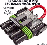 Many owners of square-body
C10s bypass a problematic ESC system entirely by swapping the factory setup
out for a standard, non-ESC High-Energy Ignition (HEI) distributor with
mechanical and vacuum advance weights. This bypasses the old computer-controlled
spark module completely and restores steady mechanical power. The same can
be done with a jumper wire with alligator clips by connecting the A and C
terminals together.
Can the ESC knock sensor system get stuck in the failsafe or limp mode?
The Electronic Spark Control (ESC) system can get stuck in its failsafe mode, which causes the engine to suffer from a permanent, significant loss of power and sluggish acceleration.
On 1981–1986 GM squarebody trucks, the standalone ESC module (typically located behind the glove box) relies on a constant signal from the knock sensor. If the ESC module loses this signal or detects an internal circuit fault, it defaults to its failsafe mode, locking the system into a heavy ignition timing retard (usually pulling around 4 to 8 degrees of timing) to protect the engine from potential detonation.
Why the ESC Gets Stuck in Failsafe Mode
Unlike modern vehicles that will throw an OBD2 check engine light for a knock sensor code, a 1985 GM system—whether carbureted or early EFI—often handles this entirely via the hardware module. The module will "fail soft" and stay stuck in retard mode if:
- The Sensor is Unplugged, Corroded, or Dead: If the single-wire knock sensor on the lower passenger side of the engine block breaks internally or its connector falls off, the circuit opens. Loss of continuity automatically triggers the failsafe state.
- Shorted or Brittle Wiring: The wire running from the sensor to the firewall passes near hot exhaust manifolds. If the insulation has melted and the wire is shorting to the frame or block, the module defaults to maximum retard.
- The ESC Module Itself Has Failed: Because these modules are now decades old, internal capacitors and circuitry degrade. A failed internal component can cause the module to permanently output a "retard" command to the HEI distributor, even if the knock sensor is perfectly healthy.
How to Confirm It:
- The Tap Test: Connect a timing light, start the truck, and bring it slightly above idle (around 1,500 RPM). Have an assistant firmly tap the engine block near the knock sensor with a wrench. If the timing drops and then returns, the system is working. If the timing doesn't budge or is already excessively retarded and sluggish, the system is down.
- The Bypass Test: To prove the ESC is stuck in failsafe, you can temporarily bypass it. Locate the 4-pin weather-pack connector near the distributor (containing black, white, green, and brown wires). If you disconnect the ESC side and jumper the black and green wires together on the distributor side, you bypass the ESC module entirely, returning the distributor to straight mechanical/vacuum advance. If the truck suddenly regains its lost power and responsiveness, the ESC system was stuck in failsafe. (Note: Premade Plug & Play ESC Bypass Modules are commercially available for testing or permanently deleting the troublesome vintage system).
Can an Old School Engine with 10:1 Compression Ratio Run Okay on 87 Octane Gas?
Actually, an old school engine with a 10:1 static compression ratio can run very well on 87 octane gas, provided the dynamic compression ratio, camshaft design, cylinder head material, and tune are set up to handle it.
Key Factors That Decide If It Will Work
- Dynamic Compression Ratio (DCR): Static compression (10:1) is only part of the story. A larger or more aggressive aftermarket camshaft with a late intake valve closing (IVC) point "bleeds off" cylinder pressure at low RPMs, dropping the dynamic compression low enough (e.g., around 7.7:1) that 87 octane will not cause pre-ignition or knock. Conversely, a tight, early-closing cam traps more air and raises the risk of detonation.
- Aluminum vs. Iron Heads: Aluminum cylinder heads dissipate heat much faster than old-school iron heads, which helps suppress hot spots and lowers the chance of detonation on lower-octane fuel.
- Quench and Combustion Design: A tight quench distance (the gap between the piston and the cylinder head at top dead center) promotes a clean, turbulent burn that resists knock.
- Ignition Timing and Fuel Mixture: Retarding the ignition timing by a few degrees or running a slightly richer air-fuel ratio can prevent pinging on 87 octane, though it may slightly reduce peak efficiency.
- Modern vs. Legacy Design: Modern direct-injection engines (like GM's LT1 or Mazda's Skyactiv) routinely run high static compression ratios (11:1 to 13:1) safely on regular 87 or 91 pump gas thanks to precise computer knock sensors, direct fuel cooling, and combustion chamber engineering. Older traditional iron-head or carbureted builds at 10:1 may struggle or knock on 87 without a proper cam and tune.
Risks of Running 87 Octane Too High:
- Detonation (Knock): Uncontrolled explosions in the combustion chamber that sound like a metallic pinging or rattling.
- Engine Damage: Severe or prolonged detonation can crack pistons, bend rods, damage rod bearings, and destroy head gaskets. [1, 2]
How Can an Old School Carbureted Engine with 10:1 Compression Ratio Burn 87 Octane Gas and Not Detonate?
An older carbureted engine with a 10:1 static compression ratio can often run on 87 octane gas without detonating because of dynamic compression (which is lower than static compression), conservative ignition timing, or engine design factors that reduce cylinder pressure and heat.
Key Reasons It Can Survive on 87 Octane
- Camshaft Overlap and Late Intake Closing: Static compression ratio (SCR) is just a geometric math calculation based on cylinder volume. Dynamic compression ratio (DCR) depends on when the intake valve actually closes. If the engine uses an aftermarket or older performance camshaft with a late intake-closing event, it pushes a portion of the air-fuel mixture back into the intake manifold at low speeds, bleeding off cylinder pressure and dropping the effective compression.
- Retarded Ignition Timing: If the ignition timing is set conservatively (with less total advance), the spark fires later in the piston's stroke. This lowers peak cylinder pressure and temperature right when the fuel mixture would otherwise be prone to spontaneous self-ignition.
- Elevation and Ambient Conditions: Operating at a higher-altitude geographic region naturally lowers barometric pressure and air density, reducing the actual mass of air filling the cylinder and keeping dynamic cylinder pressures low enough to prevent pinging on regular gas.
- Rich Carburetor Air-Fuel Mixture: Carburetors are often tuned slightly rich (extra fuel) compared to modern precision fuel-injection systems. A richer mixture cools the combustion chamber through latent heat of vaporization, helping suppress detonation.
- Low Engine RPM and Light Loads: Under gentle cruising or low-load conditions, cylinder pressures never reach the critical threshold required to make 87 octane detonate, even if the static ratio is 10:1. Detonation typically shows up under heavy throttle, hard acceleration, or towing.
- Carbon-Free or Cool Chambers: If the engine has clean combustion chambers (free of glowing carbon deposits that act as hot spots) and a well-maintained cooling system running around 180°F–200°F, it resists pre-ignition much better than a neglected, overheated motor.
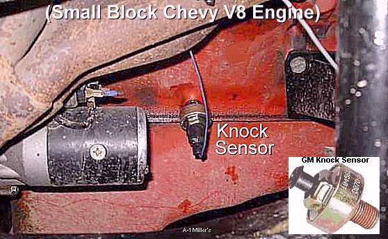 The knock sensor is threaded
into the engine block just in front of the starter, a specialized 5-pin module
HEI distributor, and a small silver control module located behind the glove
box. The knock sensor allows a high-performance engine with a 9.3:1 or higher
compression ratio to safely burn 87 octane gasoline with no damage to the
pistons when or if detonation and a pinging sound occurs.
How It Works: The knock sensor backs off (retards) ignition timing almost instantaneously - within milliseconds - the moment it detects the specific acoustic vibrations of detonation (pinging sound). It listens to engine vibrations to detect pre-ignition or spark knock. It sends a voltage signal to the engine control module so timing can be backed-off (retarded) to protect the engine from damage. On older popular Chevy small block V8 engines, this sensor is located on the lower passenger side of the engine block, in front of the starter motor. It threads into the coolant drain hole.
The rapid response operates in the following stages:
-
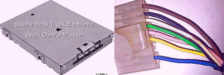 Detection: The sensor (a
piezoelectric crystal) detects the sudden shockwave of an uncontrolled explosion.
It instantly converts these vibrations into an electrical voltage signal
and sends it to the Engine Control Unit (ECU).
- Immediate Retardation: Once the voltage surpasses a pre-set threshold for knock, the ECU immediately retards the ignition timing to reduce cylinder pressure and stop the detonation. This usually happens in small steps (typically -2° to -3° per event) until the noise clears. If the knock is severe, it will pull more timing (up to -6° or more depending on the vehicle).
- Recovery / Re-learning: Once the knocking stops, the ECU holds the safe timing for a moment and then slowly begins advancing the timing back toward its optimal setting at a gradual rate (e.g., 1° per second).
- This continuous tug-of-war ensures the engine produces maximum power while keeping the engine safely out of a damaging knock zone. You can learn more about how this system balances power and safety on.
- You can detect the drop in engine power when a knock sensor detects pre-ignition (knock) and forces the Engine Control Unit (ECU) to retard the ignition timing.
- The signs range from subtle to severe depending on the severity of the knock and the specific vehicle.
Signs You Can Feel and Hear
- Sudden Power Sag: When knock occurs, the ECU instantly pulls back the timing. Yanking out just a few degrees of timing can temporarily cost the engine 5 to 20 horsepower. You may feel a brief, sluggish hesitation or flat spot during hard acceleration.
- The "Ping" Sound: You may briefly hear a metallic rattling, pinging, or "marbles in a can" sound right before the ECU reacts and pulls the timing.
Recovery Surge: Once the ECU determines the engine is no longer knocking, it will slowly advance the timing back toward its optimal mapping. This return to normal can feel like a sudden surge or pickup in power.
Continuous Power Loss: If you are running poor quality or low-octane fuel, the ECU might constantly stay in a "safe" (retarded) timing map. This results in an overall lack of pep and poor fuel economy across your entire drive.
Why This Happens (The Science)
- Optimal Timing: To make maximum torque, the spark needs to ignite the air-fuel mixture at the perfect millisecond so maximum cylinder pressure pushes the piston down right after Top Dead Center.
- The Knock Event: Advancing the timing too far causes pressure to peak too early, fighting the piston as it is moving up. This causes uncontrolled spikes in cylinder pressure (engine knock).
- The ECU Reaction: The knock sensor detects the vibration of this abnormal combustion. The ECU responds immediately by retarding (backing off) the timing to stop the knock, which sacrifices power to protect the engine.
How to Bench Test an HEI Distributor with the 5 Pin Ignition Control Module -
-
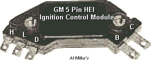 Connect the BAT terminal to
a 12 volt positive (+) battery post.
- Ground the unit to the negative (–) battery post.
- And on the connector plug with D, C, B, A, connect the A and C terminals together to make a spark. Otherwise, no spark will occur. (Broken wire in vehicle or knock sensor computer is bad.)
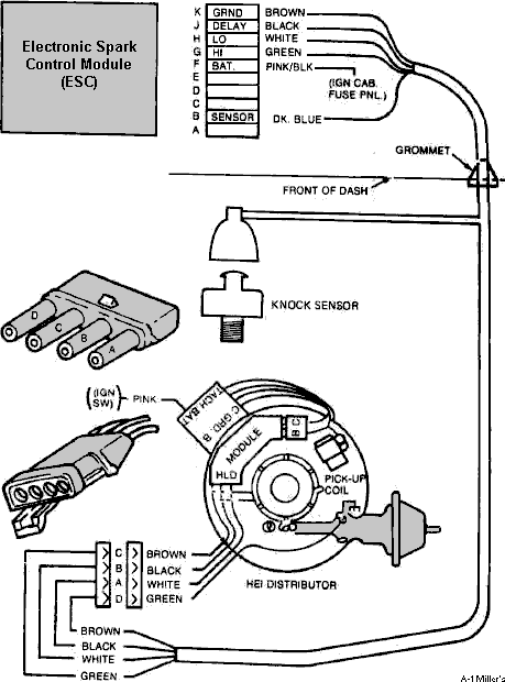 The knock sensor computer -
officially known as the Electronic Spark Control (ESC) module - is protected
by a fuse. If the vehicle loses power to this module, the engine will typically
experience a "crank, but no start and no spark" condition. The fuse is located
in the main fuse panel. It's part of the GAGE / IDLE fuse (typically a 20
amp fuse). If the dashboard fuel/battery gauges work when the key is turned
to the "ON" position, this fuse is likely not burnt.
To test the Electronic Spark Control (ESC) module (the knock sensor "computer") with the engine not running, a key-on, engine-off (KOEO) voltage test must be performed using a Digital Multimeter (DMM).In 1985 GM systems, the ESC module sits between the knock sensor and the main Engine Control Module (ECM). When it detects a knock signal, it drops its output voltage to signal the ECM to retard timing.
1. Locate the ESC Module. The standalone ESC module is a small, flat plastic box usually mounted on a bracket near the firewall, passenger-side fender, right behind the fuel pump relay or on inside the firewall behind the glove compartment. It features a 5-pin inline Weatherpack connector.
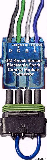 2. Identify the Wire Pins.
Look closely at the letter markings embossed on the distributor ESC plastic
connector:
- Pin A (Dark Blue wire): Signal coming from the knock sensor. (Connects to the L pin on the ignition control module.)
- Pin B (White wire): 12 volt fused ignition power input. (Connects to the D pin on the ignition control module.)
- Pin C (Green wire): Knock signal output sent to the ECM (Terminal B7). (Connects to the H pin on the ignition control module.)
- Pin D (Black wire): Engine ground circuit. (Connects to ground on the distributor.)
- Pin E: (Often empty or not used in standard truck applications).
3. Step-by-Step Electrical Testing (KOEO)
- Turn the truck's ignition key to the RUN position (engine off) and set the multimeter to DC Volts. Ground the black meter probe to a clean spot on the engine block or battery negative terminal. Backprobe the connector pins while it is still plugged into the module:
- Test Power (Pin B): Touch the red probe to Pin B. You should see 12 volts (battery voltage). If you see 0 volts, check the fuses or the ignition switch circuit.
- Test ECM Reference Signal (Pin C): Touch the red probe to Pin C. With the engine off and no knock present, you should see roughly 8 to 10 Volts. This proves the ECM is providing a reference voltage signal down the line.
- Test the Knock Sensor Bias (Pin A): Touch the red probe to Pin A. You should read approximately 4 to 6 Volts DC passing through the module toward the knock sensor.
A simple way to test a knock sensor, is to start the engine, hold the idle at 1,500-2,000 RPM, shine a timing light on the harmonic balancer timing mark, and tap the engine block with a big wrench or small hammer. (This simulates detonation or pinging sound in the engine.) If the ESC module is working correctly, the timing mark will retard, then when the tapping stops, it will advance to its previous setting. Also, if the ESC module is working correctly, the engine RPM will audibly drop and stumble momentarily as the timing retards, then recover.
4. Simulating a Knock Signal (Engine Off)
- While keeping the multimeter backprobing Pin C (Signal to ECM):
- Watch the meter screen, which should currently be reading 8–10 Volts DC.
- Take a small metal wrench or hammer and firmly tap the engine block right next to where the knock sensor is threaded into the lower block drain plug.
- The Result: If the ESC computer and knock sensor are functioning correctly, the sudden acoustic vibration will trigger the module, causing the voltage reading on Pin C to instantly drop toward 0–2 Volts for a split second.
- If the voltage remains locked at 8–10 Volts during heavy tapping, either the knock sensor is bad or the ESC module is bad.
Diagnosing a Faulty ESC Module or Broken Wiring -
If you suspect the Electronic Spark Control module is faulty, diagnose it by temporarily performing a bypass. With the distributor installed in the vehicle, unplug the 4-pin weatherpack connector coming from the distributor and connect pins A and C together on the distributor end. If the engine starts and runs normally (albeit without electronic knock timing adjustment), this proves the ESC module or its wiring harness has failed.
How to Convert an Older Small Block Chevy (SBC) for Use With a Knock Sensor -.
To make this swap work, the transplant requires a three-part standalone system as a complete package: the 5-pin HEI distributor, the separate ESC control module box, and the matching knock sensor. Unlike modern vehicles, the early GM ESC setup (commonly found on carbureted vehicles from roughly 1980–1986) operates independently of a vehicle's main computer (ECM). The distributor still retains its traditional mechanical weights and vacuum advance canister to control the base timing curve. The ESC system is only there to dynamically retard timing if it detects engine pinging.
Be Aware of Mechanical Noise: High-performance aftermarket parts like loud, tapping solid lifters, noisy gear drives, or loose exhaust headers can trick the older knock sensor. This mechanical noise can cause the system to falsely retard the timing when no actual engine knock is occurring.
Required Components for the Swap. To successfully complete the installation, you must harvest the following matching parts from the donor vehicle:
- The Electronic Spark Control (ESC) Distributor: This looks like a standard GM 4 pin HEI distributor, but the internal ignition module features one extra pin (5-pin) with an external pigtail connector to accept the signal from the ESC module.
- The ESC Module: This is a separate, small metal or plastic electronic box. On donor vehicles, it's typically mounted near the brake booster or behind the glove compartment. It acts as the signal amplifier between the sensor and the distributor.
- The Knock Sensor: This part threads directly into the engine block's coolant jacket (usually near the oil pan rail) where a NPT plug is usually located.
- The Wiring Harness: The dedicated standalone wiring loom that connects these three components together.
Wiring Requirements. The system requires very simple wiring to run standalone on an older car or truck:
- Supply a clean switched 12 volt power source to the distributor's BAT terminal and the ESC module.
- Route the dedicated factory sub-harness between the knock sensor, ESC module, and distributor.
- Ensure the ESC module and distributor have excellent, clean chassis/engine grounds.
Carbureted GM vehicles equipped with the standalone Electronic Spark Control (ESC) knock sensor system were exclusive to specific 305 CID (5.0L) V8 engines (notably the high-output L69 and select LE9 variants), as GM did not use a standalone analog ESC knock sensor setup on carbureted 350 (5.7L) engines.
Carbureted GM Vehicles with 305 ESC Systems:
- 1981–1986 Chevrolet/GMC C/K Full-Size Trucks, K5 Blazer, and Suburban: Select heavy-duty or high-compression LE9 305 truck applications featuring a stand-alone fender-mounted, firewall-mounted or behind the glove box ESC module.
- 1981–1986 Chevrolet/GMC G-Series Vans (G20/G30): Cargo and passenger vans utilizing the LE9 305 CID 5.0L carbureted engine with a knock sensor wired to an internal cabin/under-seat ESC box.
- 1983–1986 Chevrolet Camaro L69 / LG4: High-output 305 CID sport coupes equipped with a 4-barrel Rochester Quadrajet carburetor and specialized 5-pin HEI knock-retard distributor.
- 1983–1987 Chevrolet El Camino and Malibu: G-body utility/sedan models carrying the optional high-swirl or high-output carbed 305 CID engine.
- 1983–1988 Chevrolet Monte Carlo SS: G-body muscle coupes utilizing the high-output carbureted 305 CID engine option.
- 1983–1986 Pontiac Firebird / Trans Am L69: Performance F-body cars running the high-compression carbureted 305 CID setup.
A GM squarebody truck with a Turbo 350 or similar setup often features two firewall-mounted vacuum-to-electrical switches because one controls the torque converter lock-up clutch and the other manages emissions or spark retard (Electronic Spark Control / EGR system).
The Two Switches and Their Jobs:
- Emissions or Spark Retard (ESC) Vacuum Switch. Usually located on the passenger side or near the engine harness. This second switch is part of the engine management and emissions equipment (such as Electronic Spark Control or EGR/vacuum delay systems). It detects rapid changes in manifold vacuum (like a "tip-in" when you press the accelerator) and sends an electrical signal to retard ignition timing momentarily to prevent engine pinging or spark knock under load.
- Transmission Torque Converter Lock-Up Switch. Usually located near the driver’s side / brake booster. It reads engine vacuum to see when you are cruising under a light load. When high vacuum is present at steady speeds, it closes an electrical circuit to lock up the torque converter, dropping engine RPMs. When you step on the gas and vacuum drops, it opens the switch to unlock the converter.
How to make the 1963-72 Chevy and GMC truck motor mounts super strong and easier to bolt back in when reinstalling the engine:
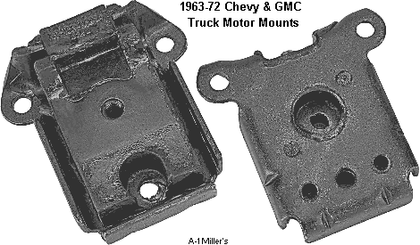 Drill
a 7/16" hole through the rubber motor mounts, install a grade 8 bolt so the
threads are exposed toward the lower part of the mount. And before installing
the engine in the truck, drill the frame motor mount holes to 5/8". The exposed
threads or "studs" on the motor mounts will allow for easy alignment to install.
Then use wide flat washers, lock nuts and grade 8 nuts on the threads of
each mount.
Adding an automatic headlight conversion to a squarebody involves installing a light sensor kit. Because the squarebody uses a highly-loaded, un-relayed factory switch, installing an inline headlight relay harness alongside the sensor kit is highly recommended to protect the factory dashboard switches and wiring.
Step 1: Gather the Tools and Parts:
- Automatic Headlight Kit: Look for universal 12 volt photoelectric kits or vehicle-specific kits like the AutoLöc Squarebody Automatic Headlights.
- Headlight Relay Kit: A standard H4 or universal 4-prong relay kit (available on Classic Parts of America).
- Tools: Wire strippers, crimpers, heat shrink, zip ties, a multimeter, and a trim removal tool/screwdrivers.
Step 2: Install the Relay Harness:
- The C10 is notorious for running the full headlight electrical load through the firewall switch, causing dim lights and potential melting.
- Disconnect the negative battery terminal.
- Mount the relays on the inner fender or radiator support near the battery.
- Connect the heavy-gauge power wire of the relay kit directly to the battery's positive terminal (or the power junction block) and secure a solid ground to the chassis.
- Unplug the factory headlight connectors. Plug the relay harness's new, heavier plugs into the headlights.
- Route the trigger wires (usually Tan for low beam, Light Green for high beam) back to the factory wiring and connect them.
Step 3: Wire the Automatic Headlight Module:
- Mount the Control Module: Find a dry, secure space under the dashboard (e.g., behind the glovebox).
- Mount the Sensor: Place the photocell sensor on the driver's side of the dashboard base (against the windshield) where it gets maximum sunlight. Route its wire under the dash and plug it into the control module.
- Connect to Power and Ground: Run the module's ground to a bare metal spot under the dash. Connect the red power wire to a 12 volt constant or ignition-switched source (depending on the specific kit's instructions).
- Connect to Light Switch: The automatic module needs to "intercept" the headlight switch. Usually, you will connect the module's trigger wire (often green) to the power-in wire going to the pull switch. Refer to a trusted AutoZone GM Full-Size Trucks 1980-1987 Repair Guide to pinpoint the correct factory wire colors for the cabin's headlight pull switch.
Step 4: Test and Secure:
- Reconnect the negative battery terminal.
- Turn the factory headlight switch to the "Auto" or "On" position (depending on how the kit wires in).
- Test the sensor by covering it with your hand. The headlights should automatically turn on after a brief delay. Remove your hand, and the lights should shut off.
- Tidy and route all loose wires cleanly away from moving engine components, and secure them with zip ties.
How an Electric Choke is Connected on an Engine That Didn't Originally Come With One:
When retrofitting an electric choke onto an older engine that originally came with a manual choke cable or a hot-air/exhaust "choke stove," the electrical and mechanical setup typically involved the following methods:
1. Electrical Power Sources -
- Option 1: The Ignition/Fuse Panel Route: Run a wire from one terminal on the choke cap through the firewall and connect it to a designated 12 volt ignition-switched terminal on the fuse box (power that is live only in the "ON" and "RUN" positions, not constant battery power).
- Option 2: The Oil Pressure Switch Route: Route the 12 volt power through an oil pressure safety switch. This ensures the choke only receives power once the engine is started and builds up oil pressure. If the engine already have an oil pressure sending unit, which powers a dash light or oil pressure gauge, a T-fitting will need to be installed in place of the oil pressure sending unit to use both the oil pressure switch and oil pressure sending unit.
2. Grounding -
-
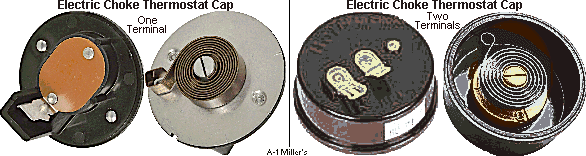 The one terminal choke cap
receives its ground through mounting to the choke housing on the carburetor.
- But on the two terminal electric choke cap, it contains a bimetallic coil that requires a solid electrical circuit. A ground wire is attached directly from the choke housing to a screw on the carburetor body.
3. How the Electric Choke Functions Day-to-Day -
- When the engine is cold, pressing the accelerator pedal one time allows the choke plate to close to enrich the fuel mixture.
- Once the ignition key was turned on and the engine starts, electricity flows to the internal bimetallic choke coil, gradually warming it up.
- After a few minutes, the choke coil tightens its tension and slowly opens the choke plate all the way.
- When the ignition is shut off, choke coil unwinds and slowly closes the choke plate until it's fully closed.
How to Connect an Automotive Electric Choke -
On a standard 12 volt electric choke cap, there is no positive or negative distinction between the inner/center and outer blade terminals because the internal heating element is a simple resistor. Electric chokes function using a bimetal spring wrapped around a ceramic ceramic heating element. Because it is a resistive load, current can flow through it in either direction to generate heat. However, how you wire them depends entirely on the style of the choke cap you have:
1. If the choke cap has two external terminals (one near the center, one near the outer edge):
- One terminal connects to a 12 volt positive (+) power source.
- The other terminal connects to a negative ground (–) on the carburetor body.
- NOTE: It does not matter which is which. You can connect positive to the center and ground to the outer, or vice versa.
2. If the choke cap has only one terminal:
- The (one) blade connects to a 12 volt positive (+) power source.
- The negative ground (–) is automatically established through the metal choke housing on the carburetor itself when the choke cap is fastened on.
An electric choke typically takes 3 to 5 minutes to fully open once the ignition key is turned on and +12 volts power is supplied to the bimetallic heating coil. And it typically draws between 1 to 3.5 amps of continuous current during normal operation, though it can experience a brief initial spike of 6 to 7 amps the moment power is applied to a cold coil.
Using a 2 Terminal Oil Pressure Switch to Activate the Electric Choke -
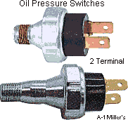 Operating an old-school electric
choke from a three-terminal oil pressure sending unit/switch is better because
it serves as a safety mechanism to prevent the choke from opening before
the engine actually starts. While the alternator (specifically the stator
or "S" terminal) was a common factory wiring choice for many vintage vehicles,
upgrading to or utilizing an oil pressure switch provides distinct technical
advantages.
The GM two-terminal oil pressure switch is used for both the dash light and electric choke, serving a dual purpose in many classic GM vehicles (such as older Chevy/GMC trucks and cars). The 2 terminal (or normally open) oil pressure switch acts as a switch for an electric choke, ensuring the choke's coil only heats up and opens the choke plate when the engine is running and producing oil pressure. General Motors introduced the 2 terminal oil pressure/choke switch configuration on small block Chevrolet (SBC) and related carbureted passenger car and truck engines around 1978–1979 as factory electric chokes and emissions requirements became widespread.
How the Two Functions Work Together:
- Choke Warning Dash Light: In many GM setups with an "idiot light" dash cluster, the circuit is tied into the dashboard choke/oil warning light. If the oil pressure drops or if there is a malfunction in the choke power circuit, the system will illuminate the warning light on the dash.
- Electric Choke Control: When the engine is off, the switch is [normally] open and no power goes to the electric choke coil. Once the engine starts and builds oil pressure (typically around 4 to 10 psi), the switch closes and sends 12 volts power to the electric choke so it can begin opening.
Key Details of the Switch and System:
- Function: The 2 terminal (or multi-terminal combination) oil pressure switch acts as a safety/power cutoff. It keeps 12 volts power from reaching the electric choke coil until the engine is running and builds oil pressure (typically 2 to 6 psi), preventing the choke from opening prematurely if the ignition key is left in the "ON" position without the engine started.
- Application Timeline: GM transitioned away from purely thermal/hot-air chokes to electric-assist and full electric chokes through the mid-to-late 1970s, making the oil pressure/choke switch standard equipment on small-block V8 applications (such as 305 and 350ci engines) starting around the 1978–1979 model year.
- Placement: Typically threaded into the engine block either near the oil filter housing or at the rear of the engine block near the intake manifold and distributor base.
How the Wiring Works:
- Incoming 12 Volt Source: One terminal of the oil pressure switch receives a switched 12 volt power source (usually connected to an ignition-hot wire or a dedicated choke fuse like a pink/white lead).
- Outgoing Wire to Choke: The second terminal connects directly to the positive terminal of the electric choke coil.
- Ground Path: The electric choke completes its circuit by grounding locally to the carburetor body.
Operational State
- Key ON / Engine Off (No Oil Pressure): The oil pressure switch is normally open, meaning the internal contacts are not connected. No power flows to the electric choke, preventing the choke from opening prematurely if the ignition key is left on without the engine running.
- Engine Running (With Oil Pressure): The engine builds oil pressure, which pushes against the switch's internal diaphragm and forces the contacts to make connection. Current flows through the switch from the 12 volt source to the electric choke, allowing the internal coil to heat up and gradually open the choke flap.
With a 2 terminal oil pressure switch used for an electric choke (common in older GM and classic vehicles), the dual-function switch and dashboard warning light operate through a shared-power or ground-return logic depending on the factory wiring design.
How the Dash Light Works
- Bulb Power Source: The dashboard choke or oil warning light receives a constant 12 volt positive signal from the ignition switch whenever the key is turned to the "ON" or "RUN" position.
- Engine Off (No Oil Pressure): When the engine is off, the internal contacts inside the oil pressure switch remain in their resting (normally closed) state, providing a path to ground or completing the circuit for the warning light. This causes the dash light to illuminate as a bulb-check when you turn the key on.
- Engine Running (Oil Pressure Rises): Once the engine starts and oil pressure builds up, the internal diaphragm pushes against a spring and opens or shifts the switch contacts. This breaks the light circuit, turning the dash light off.
- Simultaneous Choke Activation: At the same time the oil pressure closes the power circuit to the electric choke (supplying 12 volts to heat the choke coil), it separates or shifts the indicator light circuit so the light goes out.
- Warning Function: If the dash light stays on or flickers while driving, it signals either a drop in engine oil pressure or a fault/short in the choke-to-switch wiring harness.
Why the Oil Pressure Sending Unit is Better:
Feature Oil Pressure Sending Unit / Switch Alternator (Stator/S-Terminal)
- Trigger Mechanism Requires physical engine rotation and oil pressure buildup to close the internal circuit. Requires voltage from the alternator spinning, or is linked directly to the ignition circuit.
- Cold Weather Extended Cranking Keeps choke fully closed. If the engine takes 30–60 seconds of cranking to start in freezing weather, the choke receives no power and stays closed to maintain a rich fuel mixture. Prematurely opens the choke. If wired incorrectly or if the alternator produces residual voltage during extended cranking, the choke begins heating up and leaning out the mixture before the engine even fires.
- "Key On, Engine Off" Scenario Protects the battery and choke. If you leave the ignition key in the "ON" position to listen to the radio or diagnose a problem without running the engine, the choke receives 0 volts. Drains battery / Overheats choke. Depending on the wiring configuration, leaving the key on can send continuous power to the choke, heating it wide open so that it's useless when you finally try to start the car.
- Stall Protection Immediately cuts power. If the engine stalls while you are away from the vehicle, oil pressure drops, the switch opens, and power to the choke is cut—preventing a dead battery. May keep feeding power. If the ignition is still live and the alternator circuit doesn't fully isolate, the choke element will stay hot.
- Electrical Load & Voltage Provides a clean 12 volt+ loop usually pulled from a fused battery or ignition source through the switch contacts. Can cause voltage drop. Tapping directly into an alternator's stator wire introduces an extra load to the stator field, occasionally resulting in insufficient voltage (under 12 volts) that leaves the choke partially closed.
The 2-terminal oil pressure switch (or sender) is not a single universal part; instead, it is a broad design category used across thousands of different vehicle makes, models, and engine sizes—ranging from classic American V8s and Jeeps to modern imports—depending on whether the vehicle uses an oil pressure warning light, an electric dash gauge, or a variable valve timing (VVT) system. Because exact fitment depends heavily on the specific part number (such as Standard PS-144, PS-284, PS-310, or ACDelco E1805A), applications vary widely by manufacturer:
- GM (Chevrolet, Buick, Cadillac, Oldsmobile, GMC): Used extensively from the late 1970s through the 1990s (such as Chevrolet K10 trucks, Buick Century, and Electra) up to modern 4.2L or VVT-equipped engines, supporting both 2-terminal oil light and gauge configurations.
- Chrysler, Dodge, & Plymouth: Fitted on various 1988–1996 and late-80s/90s models equipped with factory oil pressure gauges or dual-purpose fuel-injection/oil circuits (such as Dodge Dakota, Chrysler LeBaron, and Plymouth Voyager).
- Jeep: Frequently used on 1981–1991 Grand Wagoneers, Cherokees, J-Series trucks, and 1996–1997 Jeep Grand Cherokees for oil pressure gauge and warning light tracking.
Using an "Old School" 3 Terminal Oil Pressure Switch to Activate the Electric Choke -
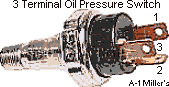 How the "Old School" 3-Terminal
System Works:
The classic GM style 3-terminal unit pulls double-duty:
- Terminal 1: Sends the variable resistance signal to the dashboard oil pressure gauge or warning light.
- Terminal 2: Accepts a fused 12 volt ignition power source.
- Terminal 3: Routes that 12 volt power out to the electric choke cap.
The connection between Terminal 2 and 3 is a physical switch that stays open until the engine fires up and creates roughly 2 to 5 PSI of oil pressure. Once pressure is detected, the switch snaps shut, sending a clean, steady stream of 12 volt power directly to the choke to let it warm up normally.
To safely and effectively wire an electric choke using an oil pressure switch, the goal is to supply 12 volts power to the choke only when the engine is actively running and building oil pressure. This prevents the choke from heating up and opening prematurely if the ignition key is left in the "RUN" position while the engine is off.
Step-by-Step Installation Procedure
- Mount the Switch: Install the 3-terminal oil pressure switch into an engine oil gallery port (commonly near the distributor or oil filter housing). If the vehicle already have an oil pressure gauge, install a metal T-fitting to run both the gauge sender and this choke switch from the same port.
- Wire the Power Input: Locate a 12 volt source that is hot only when the key is turned to "RUN" (do not use the accessory circuit or the "Batt" terminal directly without a keyed source). Run a wire through a 20-amp inline fuse to one of the outside terminals on the pressure switch.
- Wire the Choke Output: Connect a wire from the remaining outside terminal of the switch straight to the positive (+) terminal terminal on the electric choke cap.
- Ground the Choke Coil: Ensure the carburetor has a solid ground connection. If the choke cap has a dedicated ground spade, run a clean wire from it to a nearby bolt on the intake manifold.
The 3-terminal oil pressure switch (or sender) is not a single universal part; instead, a 3-pin or 3-terminal design fits a wide range of GM (Chevrolet, GMC, Buick, Cadillac, Pontiac) and other manufacturer applications spanning different eras—most commonly from the mid-1970s through the late 1990s and 2000s, depending on the specific engine and part number:
- GM Classic / Truck / Car Applications (e.g., Standard PS-140 / 3-Pin Senders): Commonly fit 1975 to 1992 (and extending through 1999 for various Chevy S10, Suburban, and truck models with 2.2L, 2.5L, 2.8L, 4.3L, 5.7L, and 7.4L engines).
- Other 3-Terminal / 3-Pin Switch Variations: Used across various domestic and imported models (Buick, Cadillac, Chevy, GMC, Isuzu, Oldsmobile, Pontiac) from the 1980s into the 2000s, where the 3 terminals typically power the oil pressure gauge, the low-pressure warning light, and/or the fuel pump relay circuit (common on GM vehicles where the oil pressure switch acts as a backup power circuit for the fuel pump).
Using the Alternator to Activate an Electric Choke -
Using a GM Delco-Remy Alternator with an External Voltage Regulator to Power an Electric Choke-
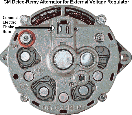 To power an electric choke
using a standard 4-pin or 5-pin automotive relay triggered by a GM alternator
with an external voltage regulator (such as a classic 10DN setup), you can
use the alternator's generator light (idiot light) wire or field/stator circuit
to switch the relay on only when the engine is actively running.
Why Use a Relay?
An electric choke is essentially a small heating element. Powering it directly through a key-on ignition switch or tapping a resistor wire can draw too much current and burn out old switches or drop voltage. A relay lets you feed a clean, full 12-volt current directly from a heavy-duty power source without overloading the harness.
Standard Relay Wiring Method (Engine-Running Trigger)
Using a standard 30-amp/40-amp automotive relay, wire the terminals as follows (referencing standard relay pin numbers):
- Pin 30: Connect to a fused 12V constant power source (such as the main BAT terminal on the alternator output or the battery side of the starter solenoid). Place an inline fuse (e.g., 10-amp or 15-amp) close to this power source.
- Pin 87: Run a wire directly to the positive terminal of the carburetor's electric choke (the choke housing is usually grounded directly to the carburetor body).
- Pin 85: Connect to ground (clean chassis or engine block ground). (Note: If using a diode-protected relay, keep Pin 85 strictly as ground).
- Pin 86: Tap into the generator/alternator warning light wire (the small wire going to the external regulator or alternator "IND" / light terminal that goes hot or grounds when charging) OR an oil pressure switch / sender wire that activates when the engine builds oil pressure.
How it works: When you turn the key, the relay stays off. Once the engine starts and the GM alternator begins charging, the trigger signal on Pin 86 energizes the coil inside the relay, closing the internal switch between Pin 30 and Pin 87. This sends full 12V power to the electric choke only while the engine is running—preventing the choke from heating up if you leave the key in the "ON" position with the engine off.
Using the Electric Choke with an Alternator with a Built-In Voltage Regulator -
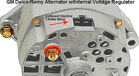 On a GM Delco-Remy 10SI
alternator, Terminal 1 (the brown wire/exciter/stator/indicator light side)
was used by GM and Ford to trigger a relay that powers the electric choke.
However, connecting Terminal 1 directly to an electric choke without a relay
is generally discouraged because the choke coil draws more current than the
indicator/exciter circuit in the alternator is designed to handle, which
can damage the alternator or cause the choke to cool down and close if the
alternator quits working or if the fan belt breaks. Instead, it's recommended
to use a dedicated relay as mentioned below or an oil pressure switch as
mentioned above.
Even a standard 12 volt automotive electric choke relay (such as Standard Motor Products RY-144 or RY-28) that's triggered by the ignition, doesn't work as well as the oil pressure switches mentioned above because the relay sends power to an electric choke coil full time only when the ignition is on or when the engine is running. The relay system works fine when the key isn't left on for a long time or when the engine starts quickly.
Understanding Terminals 1 and 2:
- Terminal 1 (R or I - Brown wire): Connects to the internal stator/idiot light circuit. It only becomes hot/active when the alternator is spinning and generating a charge. GM historically used this signal to open a relay for the electric choke so it wouldn't heat up with just the key on.
- Terminal 2 (S - Red/2 wire plug): Connects directly to the battery voltage sense circuit (often looped to the main output stud) to tell the regulator what voltage to output. It is hot all the time, meaning you should never wire an electric choke directly to it, or the choke will stay heated and drain the battery or fail to close properly when the engine is off.
The term "idiot light" (or dummy light) came about in the mid-20th century as a sarcastic nickname for simple on/off dashboard warning lights that automakers began using to replace traditional mechanical gauges.
How and Why It Started:
- Replacement of Gauges: Before and after World War II, all automobiles used active mechanical gauges (such as oil pressure, water temperature, and generator/ammeter dials) that let drivers monitor the engine's vital signs in real time and catch a problem before it caused damage.
- The On/Off Shift: Automakers (starting with companies like Hudson in the mid-1930s and expanding widely through the 1950s) began swapping these gauges out for basic binary indicator lights that only turned on when a problem had already happened (e.g., oil pressure had completely dropped or the engine was already overheating).
- The Sarcastic Meaning: Experienced auto mechanics and automotive writers (like Tom McCahill) criticized the change because the lights offered no useful sliding scale or early warning. Drivers who know how to understand the gauges called them "idiot lights" because the car assumed the operator was an "idiot" who could not understand a real gauge, and because the light only told the driver something was wrong after it was too late - effectively acting as a light for idiots, or treating the driver like one.
How to Use a Relay to Protect from Damaging a GM Delco-Remy Alternator -
A horn relay, blower motor relay or any standard 12-volt automotive relay can technically be used to power an electric choke when it is connected to a GM alternator, provided it is wired correctly.
How It Works:
- Current Protection: An electric choke uses a small heating element that draws continuous power. Running that full load directly through an old ignition switch can cause overheating or voltage drops.
- Relay Function: Using a relay lets a low-current, key-on switched wire trigger the relay, which then pulls heavy, steady 12-volt power straight from a battery or alternator source to the choke.
- Horn Relay vs. Standard Relay: A horn relay is typically a simple single-pole, single-throw (SPST) or similar electromechanical switch designed to handle momentary high-current bursts for a horn. Because an electric choke requires continuous duty rather than momentary pulses, a standard 4-pin or 5-pin multi-purpose automotive relay (like a standard Bosch-style 30-amp relay) is much more reliable and less prone to burning out over time.
Best Practices
- Continuous Duty: Ensure the horn relay (if you choose to use one) is rated for continuous duty, as horn circuits are normally built for short, intermittent use.
- Inline Fuse: Always install an inline fuse (typically 10 to 15 amps) on the power feed to the electric choke to prevent electrical fires. [1, 2]
- Switched 12 Volt Trigger: Make sure the relay's control/exciter wire is tied to a true key-on 12-volt source (not the weak 7–9V resistance wire coming off the distributor side of an old ignition coil). [1]
Any standard SPDT 12 volt, 30-to-40-amp automotive 5-pin or 4-pin relay (such as a horn or blower motor relay) can be used to power an electric carburetor choke.
Types of Relays Used
- Standard 12V Automotive Relay (30A–40A): The most common choice for a custom or aftermarket electric choke setup. A classic Bosch 332019150 Relay or any standard multi-purpose 4/5-tab relay works well.
- Dedicated OE Choke Relays: Specific vehicle models or direct-fit replacements like the Ultima Technologies 10 Amp 3 Terminal Automatic Choke Relay are designed for factory-style wiring if you are replacing an original under-hood unit.
The alternator-controlled electric choke circuit, commonly used on older vehicles (like vintage Fords or GMs) to ensure the choke only receives power when the engine is actually running. In this setup, the relay is triggered by the alternator's stator or field circuit, which then closes the contact to send 12 volts directly to the electric choke coil. If you are using a standard 12-volt electric choke and want to avoid overloading the alternator stator, a 30-amp, 4- or 5-pin standard automotive relay is the best approach.
How a Relay Setup Works:
-
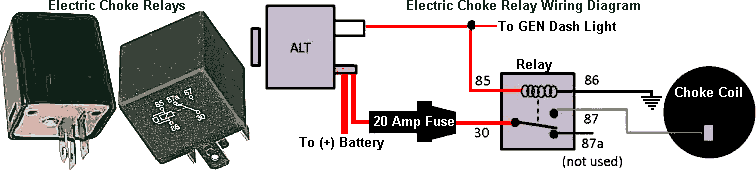 Trigger (Pin 85 / 86): Wired
to an ignition-switched source or the alternator/gen light signal so the
relay only clicks on when the engine runs.
- Constant Power (Pin 30): Wired with an in-line fuse directly to a 12 volt constant source (like the battery or the main output stud of the starter solenoid).
- Choke Output (Pin 87): Runs a fused 12 volt power straight to the electric choke element.
- Ground (Pin 85 or 86): Grounded cleanly to the chassis/body.
When an electric choke relay goes bad, it disrupts the power supply to the carburetor's electric choke coil (or the choke warning light circuit), causing the choke to either stay closed or fail to heat up properly.
Common Symptoms of a Bad Electric Choke Relay
- Choke Stays Closed (Engine Runs Rich): If the relay fails to send power to the choke coil when the engine runs, the choke plate stays closed or only opens slightly from the choke pull-off vacuum canister. This causes black smoke, rough idling, engine surging, heavy fuel consumption, and potential carburetor flooding.
- High Idle That Won't Drop: Without power to open the choke, the fast-idle cam stays engaged, meaning the engine will continue to run at a high RPM even after it has warmed up.
- Hard Cold Starts (Choke Won't Close/Engage): If the relay is stuck open or failed in a way that doesn't power the choke initially, the choke might not close properly when you try to start a cold engine, leading to hard starting or stalling until the engine builds its own heat.
- Choke Warning Light Illumination: In many classic vehicles (like older GM/Pontiac/Corvette models), a defective relay or a voltage imbalance across the relay can trigger the dashboard choke warning light to turn on.
- Alternator or Charging Anomalies: In setups where the electric choke relay is triggered by the alternator's stator (R-terminal) or oil pressure switch, a shorted relay can draw excessive current or interfere with the charging system signal.
- Buzzing Sounds: A failing or chattering relay (often caused by low voltage or a bad ground) may make a rapid clicking or buzzing noise near the fuse box or under the dash.
How Many Amps Does a Relay Draw Compared to an Electric Choke?
A standard 12 volt automotive relay coil (the control side) draws about 0.035 to 0.2 amps (35 to 200 mA), whereas a typical electric choke draws about 1 to 7 amps (starting around 5–7 amps cold and dropping to roughly 1–2 amps as it warms up).
Current Draw Comparison:
- Electric Choke Relay Coil (Control Circuit): Draws roughly 0.04 to 0.2 amps (40–200 mA) when energized. (Note: The relay contacts themselves carry high current from the battery or alternator to the choke, but the electromagnetic trigger coil only consumes a tiny fraction of an amp).
- Electric Choke (Load Circuit): Draws about 1 to 7 amps total, depending on temperature and design (e.g., pulling ~7 amps initially on a cold start and tapering down to ~1–2 amps once heated).
Key Electrical Details
- The Ratio: The choke itself draws roughly 5 to 50 times more current through its heating element than the relay's internal coil does to trigger the switch.
- Why Use a Relay: A relay allows a low-current signal (like the alternator stator or oil pressure switch) to safely control the higher current needed by the choke, keeping heavy loads off delicate dash wiring or ignition circuits.
In most cases, a weakened pressure relief spring in the oil pump causes low oil pressure. Therefore, I stretch the relief spring about 3/4" out past the housing in all of the stock oil pumps in my small block Chevy engines, and they produce around 40 - 55 PSI at idle when warmed up, and 80-100 PSI at highway speeds when warmed up. I'm not worried about the spring breaking because these are made of extremely tough material. Anyway, the increased pressure slings more oil from the rods onto the cam, lifters and cylinder walls. It also fills the hydraulic lifters more for quieter valves. I also drilled a 1/16" hole through one of the lifter oil galley plugs so oil can squirt/spray on the timing chain/sprockets, allowing these parts to last longer. Also, high oil pressure with stock/baffled valve covers may also cause the engine to burn oil through the PCV valve. A restrictor with a .3/32" hole placed in the PCV hose will prevent this. And most standard passenger car oil filters are designed to withstand minimum burst pressures of 200 PSI, which is roughly double the normal maximum operating pressure of most engines. Anyway, of all the 10+ engines that I've built since 1979, they're still going strong at 350,000 - 400,000+ miles with regular maintenance and oil changes, and no oil burning or weird sounds. This works better, and it works great. No joke.
In most cases, rather if it's a gas or diesel engine with solid lifters, insufficient valve clearances will prevent an engine from starting or it'll make it hard to start. Therefore, each valve will need to have the clearance reset to factory specs. And with the proper clearances the engine should start faster, idle smoothly, rev up quicker and produce full power.
New flat tappet lifters are ground to be slightly convex with a .001" dome, and the lobes on flat tappet cams are ground to have a .001" slope. This allows the lifters to grip and rotate on the lobes when at full lift each time the valves are opened to prevent wearing of both the lobes and lifters. The base of used lifters that's in good condition can be dressed with 400 grit sandpaper to give them a slightly convex with a .001" dome and rough surface to grip the cam lobes and create a new wear pattern.
Copper coat spray works great on head gaskets. I use it sometimes. But aluminum or silver paint also works great. Aluminum or silver paint melts when the engine heats up, creating a perfect sealing surface.
I never use gaskets for my exhaust manifolds and headers. Instead, I apply clear RTV silicone sealant and torque the bolts to specs. The reason being are: 1. silicone will not burn due to exhaust heat; 2. it fills in any imperfections between the two metals to prevent leaks; 3. the manifolds or headers will not warp between the bolts when the bolts are torqued: which is where the gaskets usually burn out, and 4. it provides a perfect flat sealing surface against the cylinder heads. And when silicone is used with headers, which provides a more or less metal to metal contact, the bolts will not loosen.
A true "cold air intake" is when the engine's intake air filtration system draws cool air from outside the engine compartment, preferably through the grille. This allows the engine to produce more power and better fuel economy. If it draws air within the engine compartment and from behind the radiator, it's considered a "hot air intake." And this causes the engine to make less power with poor fuel economy.
I'm an old-school hot rodder. One day, I met a nice lady named Holly. I said to her, "Hi Holly. I like your name. It reminds me of a 4 barrel carburetor." Then I found she has a sister named Dana. When I saw her, I thought to myself, "Dang, she has a nice rear end!"
Ford oil pump driveshafts are categorized primarily by hex size (1/4-inch or 5/16-inch) and block/deck height. The 1/4-inch hex driveshaft is most famously shared across the classic Ford Windsor small-block V8 family (such as the 221, 260, 289, and 302 cubic-inch engines), as well as standard Ford FE big-block V8s like the 390.
Engines Using a 1/4-Inch Hex Driveshaft:
- Small Block Windsor (8.2 inch deck): Ford 221, 260, 289, and 302 (including 5.0L EFI blocks, though distributor engagement depth can vary slightly).
- Fuel-Injected Big Block Series: Ford FE engines (such as the 390, though length varies by application; note that FT truck variants use a thicker shaft).
- Industrial / Tractor Engines: Certain Ford industrial and agricultural engines (like the 134, 172, and 192 series, which can share or adapt 1/4-inch hex profiles).
Engines Using a 5/16-Inch Hex Driveshaft (Not Interchangeable)
- Small Block Windsor (Tall deck): Ford 351 Windsor (351W uses a larger 5/16-inch hex compared to the 302's 1/4-inch hex).
- Cleveland / Modified V8s: Ford 351C, 351M, and 400.
- Big Block Ford (385 Series): Ford 429 and 460.
- FT Truck Engines: Ford 361 and 391 heavy-truck engines (larger hex than standard FE 390).
Which oil pump driveshaft material works better than the OEM one in a Ford engine?
Heat-treated chrome-moly steel (specifically 8740 chromoly or ARP2000 alloy steel) works much better than the stock OEM shaft. Popular upgrades like the ARP Oil Pump Driveshaft Kit or Ford Performance Heavy Duty Oil Pump Shaft feature a larger diameter and higher tensile strength to prevent catastrophic snaps under high RPM or heavy oil loads.
Why Chrome-Moly Outperforms OEM:
- Higher Tensile Strength: OEM shafts are mild steel and prone to twisting or snapping. Chrome-moly options are heat-treated up to 170,000–220,000 psi.
- Larger Mid-Shaft Diameter: Aftermarket heavy-duty shafts use a thicker center section (where OEM shafts typically shear) without interfering with the block.
- Resists High-Volume Stress: If you run a high-volume/high-pressure oil pump or thick racing oil, a stock shaft can easily fail and destroy the motor.
- Precision Hex Ends: Upgraded shafts often feature CNC-milled (rather than broached) hex ends with a sturdier retaining washer to keep the shaft from lifting out of the pump.
Contact us - [Return To Previous Paragraph, Section or Website]

 To
place an order, please send your item(s) for repairing, and/or for customer
service assistance, and FREE honest and accurate technical support, contact:
A-1 Miller's Performance Enterprises, 12091 N Route B, Hallsville, MO (Missouri)
65255-9604 USA. Please call in your order or send an email with a list parts
you need and your contact information.
 Phone: 1-573-881-7229 (cell;
call, text or leave voicemail). Please call Monday-Friday, 9am to 5pm, Central
time zone, except holidays. If no answer, please try again later. Please
be patient when speaking with me on the phone because I stutter.
 E-mail:
pullingtractor@aol.com. A-1 Miller's
shop is open to the public Monday-Friday, 9am to 5pm, Central time zone,
with an appointment on weekends, except holidays. If you're the kind of person
who don't trust delivery/shipping companies (mis)handling your high-dollar
and fragile merchandise, you can make the long drive to A-1 Miller's new
shop (click image to the right) to personally purchase parts, or drop off
and/or pick up your carburetor, clutch assembly, and/or other parts for repairing
and/or rebuilding. Or visit our new shop to drop off your parts. Please contact
us before coming so we'll be at our shop waiting for your arrival. When you
visit our shop, you will be dealing directly with the owner for the best
customer service. "The road to a [trusted] friend's house (or shop) is
never long." Don't sacrifice quality workmanship for distance.
Payment Options below.
Photos
of our new building/shop are posted here!
12091 N Route B, Hallsville, MO - Google Maps. The
reason I have never made any YouTube videos is because I stutter. I'm afraid
the viewer's mockery and negative comments would take all the educational
benefits and fun out of them.
Payment Options, and We Ship to Canada and
Worldwide 
Item(s) in a package or cushioned envelope weighing less than 1 lb. is sent
by US Postal Service Airmail Letter Post for a 4-7 days delivery. Packaged
item(s) weighing over 1 lb. and up to 66 lb. is sent by US Postal Service
Airmail Parcel Post for a 4-10 days delivery. I cannot use the US Postal
Services' Flat Rate Priority Mail envelopes and boxes to ship outside U.S.
territories. Item(s) weighing over 67 lbs. or more is sent by FedEx Ground
or equivalent services. We try to keep our shipping cost to customers within
reason. Therefore, we don't ship our products in a fancy-looking package
with our company name and/or logo on it because most customers will just
toss it in the trash after they remove the contents. And being there is no
USPS tracking number outside the US, all I can do is make sure I write your
address correctly on the customs form and on your package.
My websites are not set up to process orders and accept payments. Therefore, I will need your name, complete and correct postal mailing address and phone number. And for payment options, I accept cash (in person), USPS Postal Money Orders, cashier's checks and business checks. I do not accept credit/debit cards. Or to make a payment to me through PayPal, please click this link: https://www.paypal.com (username: pullingtractor@aol.com). And please use PayPal's "Friends and Family" option to ensure that I receive the full amount or add 3% to the total amount to cover PayPal's processing surcharge. I also accept Venmo (username: Pullingtractor) and Cash App (username: pullingtractor) please add 2% for Cash App's surcharge as well). And be sure to mention a description of what the payment is for with your full name, postal address, phone number and email address. If sending a money order or cashier's check, please include a note in the envelope with your name, complete mailing address, phone number, email address and a description of what the payment is for. I'll make a note of your order when I have all your information, and I may have to order some of the parts on your list, which should take a few days to come in, but I will send everything to you as soon as the parts are in stock after I receive your payment.



Return To Previous Website | Top of Page | Copyright © 1996-Present. This website created, designed and maintained by A-1 Miller's Performance Enterprises