 Instructions to install A-1 Miller's
Flywheel-Triggered Electronic Ignition Conversion Kit for Kohler engines
K241, K301 and K321 with the 8" flywheel and starter/generator. NOTE:
It's kind of hard to explain where to locate and install the PerTronix Ignitor
sensor/module. But I'll do my best to explain it it here. I need to make
a YouTube video showing this procedure soon.
Instructions to install A-1 Miller's
Flywheel-Triggered Electronic Ignition Conversion Kit for Kohler engines
K241, K301 and K321 with the 8" flywheel and starter/generator. NOTE:
It's kind of hard to explain where to locate and install the PerTronix Ignitor
sensor/module. But I'll do my best to explain it it here. I need to make
a YouTube video showing this procedure soon.
-
 Position the flywheel
when the S mark on flywheel is aligned or centered with the
hole in the flywheel shroud. The S mark may need to be highlighted
with a
Silver Sharpie.
Position the flywheel
when the S mark on flywheel is aligned or centered with the
hole in the flywheel shroud. The S mark may need to be highlighted
with a
Silver Sharpie.
-
At (approximately) the 10:30 position on the bearing plate, measure outward
from the bearing plate approximately 1 inch and place a mark with the
Silver Sharpie on the outside of the flywheel. It's at
this spot the trigger screw (with the magnet and rubber washer) is installed.
NOTE: The 1" height allows the screw/magnet/rubber washer to clear the
flywheel shroud mounting boss located at the 4:30 position on the bearing
plate.
-
 Acquire, preferably, a
TAPER 6-32 UNC hand tap and a
small T-handle tap wrench, and very carefully cut a 6-32
UNC threads in the flywheel at the spot and with a
high strength liquid threadlocker
(Red Loctite, Permatex or equivalent), install
the supplied trigger screw/magnet/rubber washer (weighs approximately 1/10
oz. / 2.8 grams). The screw head is magnetized to trigger the spark.
Click/tap here to learn
how to professionally cut new threads. NOTE: The hall effect ignition
module is activated by the South pole of the magnet, so do not remove the
magnet from the screw! And the rubber washer prevents the delicate rare earth
magnet from possibly breaking when lightly fastened against the uneven/rough
casting on the flywheel. Tighten screw just when the rubber begin to bulge,
and allow the threadlocker to dry and harden overnight.
Acquire, preferably, a
TAPER 6-32 UNC hand tap and a
small T-handle tap wrench, and very carefully cut a 6-32
UNC threads in the flywheel at the spot and with a
high strength liquid threadlocker
(Red Loctite, Permatex or equivalent), install
the supplied trigger screw/magnet/rubber washer (weighs approximately 1/10
oz. / 2.8 grams). The screw head is magnetized to trigger the spark.
Click/tap here to learn
how to professionally cut new threads. NOTE: The hall effect ignition
module is activated by the South pole of the magnet, so do not remove the
magnet from the screw! And the rubber washer prevents the delicate rare earth
magnet from possibly breaking when lightly fastened against the uneven/rough
casting on the flywheel. Tighten screw just when the rubber begin to bulge,
and allow the threadlocker to dry and harden overnight.
-
Once the screw (with the magnet and rubber washer) are installed in the flywheel,
you can now locate and mark exactly where to install the bracket with the
PerTronix Ignitor sensor/module on the bearing plate. It's important that
the trigger screw, when installed on the flywheel, is centered with the sensor
on the Ignitor to produce a spark and/or avoid a misfire.
-
Place the bracket with the Ignitor on the bearing plate with the sensor aligned
with the spot on the flywheel, and use a
Black Sharpie to locate and mark midway in the two adjustment
slots in the bracket where to drill 3/32" holes.
-
Acquire, preferably, a
TAPER 4-40 UNC hand tap and a
small T-handle tap wrench, and very carefully cut two 4-40
UNC threads in 3/32" holes that's drilled in the bearing plate.
-
Install the two 4-40 screws with the lock washers and flat washers in the
slots and set the clearance between the Ignitor and screw head at .010" -
.030". Once the clearance is set, securely tighten the stainless steel 4-40
screws.
-
IMPORTANT
- Gently rotate the flywheel back and forth by hand to check and see that
the Ignitor does not make contact with the screw head. If the Ignitor makes
contact with the screw while the engine is running and becomes damaged, it
may be rendered useless and inoperable.
-
Drill a 5/16" hole through the bearing plate behind the Ignitor and route
the wires from the Ignitor to the ignition coil on the flywheel shroud. Bevel
or chamber (wallow out) the drilled hole, and either use a rubber grommet
or apply
clear RTV silicone adhesive sealant in the hole and around
the wires to hold the wires rigid to prevent the insulation from rubbing
and possibly being shorted.
-
 Remove the ignition points,
condenser and pushrod, and block-off the points pushrod hole with the supplied
plate. Apply silicone sealant around the pushrod hole to prevent an
oil leak. Disconnect and do away with the wire to the points and condenser.
Remove the ignition points,
condenser and pushrod, and block-off the points pushrod hole with the supplied
plate. Apply silicone sealant around the pushrod hole to prevent an
oil leak. Disconnect and do away with the wire to the points and condenser.
-
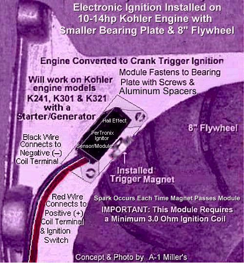
Wire Connections: Connect the
RED wire from the Ignitor to the coil
positive [+] terminal (which connects to the ignition switch and battery
positive (+) post), and connect the BLACK wire from the Ignitor to
the coil negative (–) terminal. IMPORTANT! If wires are mistakenly
connected in reverse, the BLACK Ignitor will burn up instantly when
powered up. A
diode can be connected to the
RED wire to prevent this from happening.
Also, the BLACK Ignitor may burn up if the ignition switch is left
on after approximately 5 minutes with the engine not running. The Ignitor
II will shut off automatically after approximately 5 minutes if the ignition
switch is left on with the engine not running and resume full functionality
after a few minutes. And being the Ignitor II is internally diode-protected,
it will not burn up if wires are mistakenly connected in reverse when powered
up.
-
Connect the spark plug to the spark plug wire, and place it on a metal part
of the engine. Turn on the ignition switch to supply power to the ignition
system. NOTE: With the engine not running, and when the ignition switch
is first turned on, a single "test" spark may occur at the spark plug, which
is normal with this type of system and poses no harm.
-
Now rotate the flywheel back and forth by hand when the screw passes the
Ignitor and observe the spark plug for a strong, audible "snappy" blue spark.
FYI - The blue color is made by burning of the hydrogen, nitrogen and
oxygen in the atmosphere when they are energized, and the snapping sound
is breaking of the sound barrier, resulting in a very tiny
sonic boom released from the rapid burning and explosion
of the hydrogen, nitrogen and oxygen.
-
The engine is now ready to start. And when it does, it should run very well
and produce more power.
Customer can reuse the same [copper core/non-resistor] spark plug, [metal
core] spark plug wire and [minimum 3.0 ohm] ignition coil
(click here to learn how to check
the primary ohms resistance in a coil), if all of these are in good
condition. Set the spark plug gap .025" and place the spark plug on a grounded
metal part of the engine. Turn the ignition switch ON to supply power to
the coil, and rotate the flywheel side to side by hand so the magnet passes
the module and observe for a strong, audible "snappy"
blue spark at the spark plug's tip.
IMPORTANT: Use a new copper core/non-resistor AC Delco, Autolite or Champion
spark plug of the correct type gapped at .025" and a metal core spark plug
wire for longer coil life. Use of a
resistor type spark plug
or carbon core spark plug wire will void warranty.
For customer service assistance, and FREE honest and accurate technical
support, please contact: A-1 Miller's Performance Enterprises | 12091 N.
Route B | Hallsville, MO (Missouri) 65255 USA | Phone: 1-573-881-7229
(cell/text). Call any day, Monday-Friday, 9am to 5pm, Central time zone.
If no answer, please try again later. E-mail: pullingtractor@aol.com.