Chrysler / Dodge / Plymouth Electronic Ignition Control Module/Unit
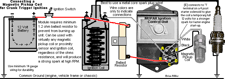
Wiring Connections/Diagram with a Magnetic Pickup Coil
This module requires a minimum 1.2 ohm ballast
resistor to prevent from burning up unit. Can be used with virtually
any magnetic pickup coil or proximity sensor and ignition coil, regardless
of the ohms resistance or voltage output, and will produce a strong spark
so the engine will idle smooth and accelerate quickly to full speed (wide
open throttle) with no hesitation or misfire.
IMPORTANT:
The coil and/or module may burn up if the ignition switch is left on for
more than 5 minutes with the engine not running.
-
 Connect the wires on the magnetic
pickup coil to the [A] and [B] terminals on the module. NOTE:
Due to
electrical
polarity of certain magnetic pickup coils, it may be necessary to connect
these two wires and terminals one way or the other so the engine will
accelerate.
-
Connect the ignition coil negative (–) terminal to the [D] terminal
on the module. For competition pulling - if the grounding-type killswitch
is used, connect the ungrounded wire from the killswitch to this terminal.
Or for a generator engine, connect this terminal with a semiconductor rectifier
diode to "excite" or temporarily energize the field windings in the
generator.
-
Connect the [C] terminal to a minimum 1.2 ohm ballast resistor, and
to the positive (+) terminal on the ignition coil and to the ignition switch
(battery positive (+) post).
-
(Optional) The [E] terminal (may not be present on certain modules)
connects to the "I" (Ignition) terminal on a
self-grounding 4-terminal starter solenoid to give
the coil temporary full 12 volts for a stronger spark for faster cold engine
start up. NOTE: If [E] is connected directly to the coil full-time
and the engine is ran for a long period of time, the coil could overheat
and eventually burn up. (The module does NOT have a built-in timing retard.)
-
Body of module must be connected to engine/chassis ground (battery negative
(–) post).
Compliments of Brian Miller
 Connect the wires on the magnetic
pickup coil to the [A] and [B] terminals on the module. NOTE:
Due to
electrical
polarity of certain magnetic pickup coils, it may be necessary to connect
these two wires and terminals one way or the other so the engine will
accelerate.