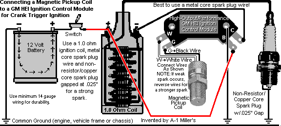
GM 4-Pin HEI Electronic Ignition Control Module Wiring
Connections/Diagram with a Magnetic Pickup Coil
This electronic ignition system operates with full 12 volts. It is recommended
only for ordinary lawn & garden equipment. In order for the engine to
accelerate at full RPM, the magnetic pickup coil requires a
high-output/performance 4-pin GM HEI module, 1.0 ohm ignition coil, metal
core spark plug wire and a copper core spark plug gapped at .025".
IMPORTANT:
The coil and/or module may burn up if the ignition switch is left on for
more than 5 minutes with the engine not running. (The module does
NOT have a built-in timing retard.)
-
 Connect the White wire on the
magnetic pickup coil to the [W] terminal on the module.
-
Connect the Black wire on the magnetic pickup coil to the [G]
terminal on the module. NOTE: Due to
electrical
polarity of certain magnetic pickup coils, it may be necessary to connect
these two wires one way or the other so the engine will accelerate.
-
Connect the ignition coil negative (–) terminal to the [C] terminal
on the module. For competition pulling - if the grounding-type killswitch
is used, connect the ungrounded wire from the killswitch to this terminal.
Or for a generator engine, connect this terminal with a semiconductor rectifier
diode to "excite" or temporarily energize the field windings in the
generator.
-
[B] terminal on the module connects to the ignition coil positive
(+) terminal and to the ignition switch (battery positive (+) post).
-
Mounting holes in the module body must be connected to engine/chassis ground
(battery negative (–) post). When mounting the GM 4-pin HEI module,
always fasten it with
dielectric, thermal or heat sink grease/paste on a clean,
flat aluminum plate with plenty of fresh air circulation to dissipate the
heat while in operation.
Compliments of Brian Miller
 Connect the White wire on the
magnetic pickup coil to the [W] terminal on the module.
 Connect the White wire on the
magnetic pickup coil to the [W] terminal on the module.